The effect of time-periodic base angular motions upon dynamic response of asymmetric rotor systems is investigated in this article. Both the disk and rotating shaft with asymmetric cross sections are considered. The rigid rotor base rotates around the three axis with time-varying angular speeds. Equations of motion for every components (asymmetric disk and shaft elements) are derived to assembe the finite element model of the whole rotor-bearing system. Due to the rotor asymmetries and angular motions of the rigid base, the finite element model has time-variable mass, gyroscopic, and stiffness coefficients. Parametric instability regions and rotor center orbits are compared with references’ results for model verifications. Then, forced responses of the system under unbalanced excitations, shaft asymmetry, and base angular motions are obtained. Effects of various types of angular motions, amplitudes, and frequency of base motions upon the response spectra and external resonances are discussed. As long as the periodic base angular motion is considered, both the response spectra and external resonances change significantly. Additional frequencies, including base frequency and combined frequencies, are found in the response spectra. Besides the critical and half-critical resonances (for the asymmetric rotor system), there are multiple resonances after considering the periodic base motions.
It is common to find the rotor with asymmetric cross sections in the field of rotating machinery. Shaft with rectangular cross section, open-edge crack, or a key way and shaft of a two-pole turbo-generator are typical examples of asymmetric rotors. The non-symmetric cross sections cause the inertia and stiffness in two principal planes different and induce parametric excitations to the rotor system. In a remarkable paper presented in 1933, the asymmetric properties in rotor system was first noticed by Smith.1 In the 1960s, Crandall and Brosens2 and Yamamoto and colleagues3,4 first conducted quantitative studies on the dynamic behaviors of asymmetric rotors. Since then, extensive work has been done on the asymmetric rotor dynamics.5–18 According to the types of rotor models used in the analysis, current literature could be divided into three groups: the Jeffcott rotor model (or lumped parameter rotor model),5–9 the transfer matrix model,10–12 and the finite element (FE) rotor model (FE model (FEM)).13–18 If one considers the research contents, the current literature could be distinguished into parametric instability analysis5–11,15,17 and steady-state response analysis.12–14,16,18
It should be noted that the above-mentioned literature all assumed that the rotor supports are fixed without motions. In reality, the rotors supported by moving bases are also encountered frequently. Rotating machines installed on transportation systems belong to such type of rotors. Over the past 20 years, the dynamic behaviors of general rotor systems under moving bases have been paid sufficient attentions by various scholars. Considering a simple Jeffcott rotor installed in an aircraft, Lin and Meng19 first studied the large linear and angular base motions induced by the maneuver flight. They discovered that the flying status of the aircraft has significant effect on the shaft’s unbalanced response. Lee et al.20 considered a base-transferred shock force and utilized a direction integration scheme to obtain the rotor’s transient response. Driot et al.21 and Duchemin et al.22 focused their study on the whirling orbits and parametric instability caused by base angular motions. Semi-analytical expressions of instability boundary of a simple Jeffcott rotor system were obtained using the multiple scales method. Later, they also considered the random base motions for stochastic rotor dynamic analysis.23 El-Saeidy and Sticher24 analyzed the dynamic behaviors of a rigid rotor-bearing system under both imbalance and harmonic base excitations. Saha et al.25 calculated the dynamic response of an uniformly spinning shaft with a non-central disk mounted on a precessing base. Transverse cracks are frequently found in the rotor’s shaft. Recently, Lin et al.,26 Jing et al.,27 and Yang et al.28 studied the coupling effects of moving base on the cracked rotor dynamic behaviors. Through sensitivity analysis, Han and Chu29 discovered some unique spectra for detecting various transverse cracks in base-excited rotating machinery. For a rotor system with rub-impact fault and cubic stiffness supports, Hou et al.30 found some typical nonlinear phenomena induced by the aircraft hovering flight. As the base motions would induce severe vibrations to rotor system under certain conditions, several researchers also presented the active control method using the electromagnetic actuators.31–33
From the above literature, one can see that both linear and angular base motions not only cause external force excitations but also internal excitations to the rotor-bearing system. It is well known that the rotor asymmetry results in parametric excitations to the system. Thus, it is foreseeable that the dynamic behavior of flexible rotor-bearings would be greatly changed after considering both the moving base and rotor asymmetry simultaneously. To the knowledge of the authors, no publication is available in the open literature that reports the effect of moving bases on the dynamic response of asymmetric rotor-bearing systems.
Thus, this article tries to reveal the effect of time-periodic base angular motions upon dynamic response of asymmetric rotor systems. Both the disk and rotating shaft with asymmetric cross sections are considered. The rotor base is assumed to be rigid and rotates around the three axis with time-varying angular speeds. Utilizing the energy theorem and Lagrange’s principle, the equations of motions for every components (asymmetric disk and shaft elements) are derived to assemble the FEM of the whole rotor-bearing system. Due to the rotor asymmetries and angular motions of the rigid base, the FEM has time-variable mass, gyroscopic, and stiffness coefficients. Before numerical simulations, the established rotor-bearing model is validated through instability and steady-state response analysis with reference results.16,21 Then, forced steady-state responses of the system under unbalanced excitations, shaft asymmetry, and base angular motions are analyzed numerically. The effects of various types of angular motions, amplitudes, and frequency of base motions upon the response spectra and external resonances are discussed. Finally, some conclusions are summarized.
FEM
In order to derive the FEM, the following assumptions should be explained:
Rigid base is assumed and its mass center is at the left bearing (see Figure 1).
There are three coordinate systems defined for modeling both rotor and base motion: the inertial frame of reference , frame of moving base , and rotor frame , which are also identified in Figure 1.
The rotation speed of the rotor shaft is assumed to be constant and denoted by . The rigid motion rotates around the three axis of the frame and the time-variable angular motions are denoted by (pitching), (rolling), and (yawing).
Asymmetric rotor-bearing system on moving base with various coordinate systems.
The asymmetric disk
Four degrees of freedom, including two translations and two rotations , are considered for the rigid asymmetric disk node. Its nodal displacement vector is then written by . It is easy to write the expressions of kinetic energy of a rigid disk as follows
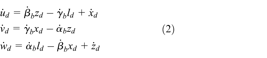
where are, respectively, the mass, two diametral mass-moments of inertia, and polar mass-moment of inertia of the disk located at a distance from the left bearing. For the asymmetric disk, one has . The mean value of the diametral moments of inertia is introduced as , and the relative inertia asymmetry of the disk is defined by . The inertia ratio is defined as . The and are, respectively, absolute translational and angular velocities of disk node with respect to the inertial frame . For the absolute translational velocities, one can write
Three angles, , are utilized to describe the movement of rotor frame with respect to the base frame . As the disk rotates constantly with angular speed , one has . There are three steps in order to orientate the disk. First, it is rotated by angle around axis , then by angle around the new axis , and finally by angle around the new axis . Thus, the absolute angular velocities of the disk could be derived by transforming the coordinates as
As the is constant, . According to Lagrange’s principle and ignoring the high order terms involving slopes, one can obtain the equations of motion for an asymmetric disk under base angular excitations as follows
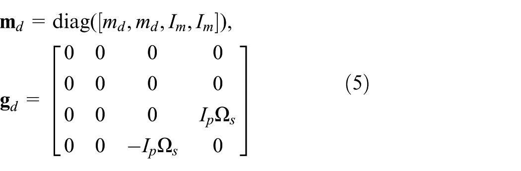
where is the constant mass and gyroscopic matrices and
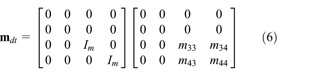
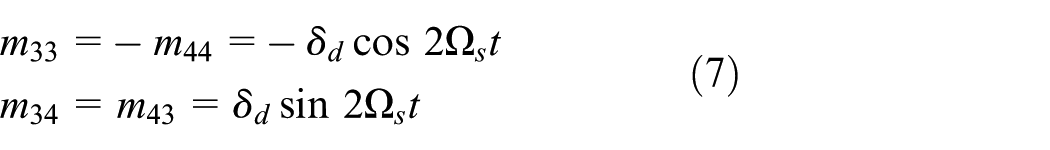
The represents the self-gravity force and unbalanced excitations of the disk. In equation (4), the are additional mass, gyroscopic, and stiffness matrices induced by the disk asymmetry and time-varying base motions. Moreover, the base motions also induce external excitations to the disk equations, and the expressions are denoted by . Through simplification and arrangement, one can obtain the expressions for the additional matrices and vectors as follows
with
with
with
with
The unbalanced mass of the disk is denoted by with eccentricity and phase angle (with respect to the axis ). Similar with that of the derivation of disk equations, the kinetic energy of the unbalance mass could be expressed as
where are the absolute velocity of the unbalance mass and are given by
According to Lagrange’s principle, the unbalanced mass excitation vector is written as follows
The asymmetric flexible shaft
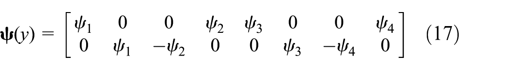
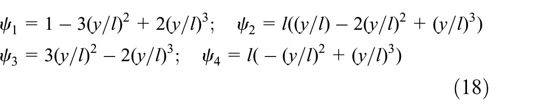
Two-node Euler beam is used to model the flexible shaft elements. The degrees of freedom include the nodal transverse deflections and slopes in the rotor frame as . In order to calculate the transverse displacements of a pint inside the shaft element, an element shape function should be defined. For the Euler beam element, the expression of is given by
with
where is the element length. The transverse displacements of a pint inside the shaft element are calculated through interpolation as . Then, one can obtain the total kinetic energy of an asymmetric shaft element as
in which are the material density and area of shaft cross section. and are the second moments of area about principal axes and of the shaft, respectively, and is the polar moment of area. For flexible shaft with asymmetric cross sections, one has . Similar with that of the disk, three parameters are defined: , , and . The and represent the absolute translational and rotational velocities of the shaft element and could be derived similarly with that of disk (see equations (2) and (3)). By substituting different components of translational and rotational velocities and into equation (19), the detailed expression for the could be obtained. The strain energy due to bending for the asymmetric shaft element is written as
where are the displacements of the center of the cross section in fixed coordinates, is Young’s modulus of the shaft material, and the operator (·)″ represents the second partial derivative of the operand with respect to axis . According to Lagrange’s principle, the equations of motion for the shaft element considering the expressions of and are obtained as follows
Similar with that of disk model, the constant mass, gyroscopic, and stiffness matrices of the shaft element are denoted by . The proportional damping coefficient is used to reflect the shaft material damping effect. is the gravity force vector. Additional time-dependent mass, gyroscopic, and stiffness matrices of and external force excitations are found in the shaft element equations due to the shaft asymmetry and time-variable base motions. Their expressions are given as follows
It is noted that in the above equations, the appeared in the time-variable coefficients should be substituted by for asymmetric shaft elements. In addition, the time-periodic stiffness matrix induced by the shaft asymmetry is given by
Bearing support
Linear flexible bearing model is adopted in this study, and the influence of slopes and bending moment is neglected in the model. The expressions for the stiffness and damping matrices and could be found in Nandi and Neogy.17
Global FEM equations
Without loss of generality, the harmonic functions are utilized to simulate the time-periodic base motions.21–23 The angular motions of the base are assumed to vary harmonically with the same frequency ()
where the constant and time-variant amplitudes of the base angular motions are denoted by and , respectively.
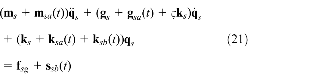
Through assembly of element equations of motion for the asymmetric disk and flexible shaft, the FEM for the whole rotor-bearing system under base angular excitations is obtained as follows
where is the ( is the element number) dimension global displacement vector; are the dimension mass, gyroscopic, damping, and stiffness matrices of the system, and the symbol ∑ represents the assembly of FE matrices after appropriate globalization method is followed. The additional time-varying mass, gyroscopic, and stiffness matrices and external force vectors are expressed as
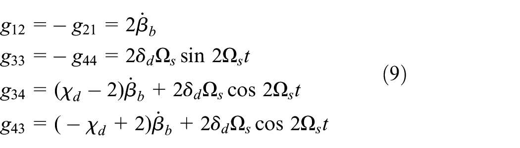
Without base angular motions, the of asymmetric rotor system are all time-periodic with the frequency of . After considering the harmonic base motions, besides the , the time-varying elements of the above matrices contain multiple frequencies, including . This can be proved from equations (9) and (11) through simple trigonometric calculations. The external force vectors also contain multiple frequencies as long as the base angular motions are taken into account.
Computations and discussions
Model validation
The rotor model of Oncescu et al.16 is adopted here. The disk is symmetric () and the shaft is asymmetric (). The parameters of the rotor system are , , , rotor length , , , , , and . The shaft is divided into five elements and the disk locates at node 3. The proportional damping of the shaft is neglected, that is, . The stiffness and damping coefficients of left bearing are , , , , , and . Similarly, right bearing’s parameters are , , , , , and .
Without considering the base angular motions, the parametric instability induced by the asymmetric rotor could be computed numerically utilizing the discrete state transition matrix (DSTM) method.34 Both the obtained instability regions and the results in Oncescu et al.16 are shown in Figure 2. It is shown that the obtained instability regions of this study are in good agreement with those of Oncescu et al.,16 indicating that the asymmetric rotor model derived in this study is believable.
Instability comparisons for the asymmetric rotor-bearing system without base angular motions: (a) results of Oncescu et al.16 and (b) results of this study.
The dynamic response of the symmetric rotor-bearing system () obtained by numerical integration method (Runge–Kutta method) is verified with the results of Driot et al.21 The shaft is divided into four elements, and the disk locates at node 4. The bearing stiffness coefficients are to simulate the simply supported boundary condition. The rotor parameters are set to be the same with Driot et al.21 The pitching base motion with and three values of frequency are, respectively, considered in the analysis. The rotating speed is and the shaft center orbits of the disk nodes are given in Figure 3. The corresponding results of Driot et al.21 are also presented in Figure 3. It is shown that the ranges of the trajectory obtained by this study are consistent with the reference ones, while slight differences could also be found in the shapes of trajectory. In Driot et al.,21 the sinusoidal shape function is used to obtain the 2-degree-of-freedom rotor model. As the disk does not locate at the mid-span, such treatment might cause the differences.
Shaft center orbit comparisons for the rotor-bearing system under pitching base motion and : (a, c, and e) results of Driot et al.21 and (b, d, and f) results of this study: (a) ωb = 251.2 rad/s, (b) ωb = 251.2 rad/s, (c) ωb = 376.8 rad/s, (d) ωb = 376.8 rad/s, (e) ωb = 502.4 rad/s, and (f) ωb = 502.4 rad/s.
Parametric instability
In the following analysis, the rotor model of Oncescu et al.16 is adopted, and the only difference is that the disk location is moved to node 2. Before instability analysis, the first order of whirling frequency varying with rotating speed is shown in Figure 4. Both the asymmetry and base angular motions are neglected. The first order of backward and forward critical frequencies are and , which are also marked in Figure 4.
Whirling analysis of the symmetric rotor-bearing system without base angular motions.
Without base movements, instability regions of the asymmetric rotor system are obtained numerically by the DSTM method and presented in Figure 5. Three values of proportional damping of the shaft, that is, , are considered in the analysis. It is shown that three instability regions, of which the starting points are about , appear in Figure 5. They are identified as the two primary instability regions and one combination instability region according to the parametric vibration theory.35 As long as the damping is considered, all the instability regions are reduced gradually. Especially for the lower asymmetries , the instability regions have been vanished.
Instability regions for the asymmetric rotor system without base movements: (a) , (b) , and (c) .
Dynamic response
The forced steady-state response of the system under unbalanced excitations, shaft asymmetry, and base angular motions will be analyzed in this section. If the system is in unstable region, the response amplitudes will be enlarged exponentially with time under initial conditions. Obviously, in this case, study on the dynamic response of the system does not make any sense. Thus, the system should be stable in dynamic response analysis. According to the instability regions in Figure 5, the shaft asymmetry and damping are chosen as and . The unbalanced mass excitations are and . In the following, the dynamic response of the system under pitching, rolling, and yawing motions are analyzed.
Pitching base motion is considered
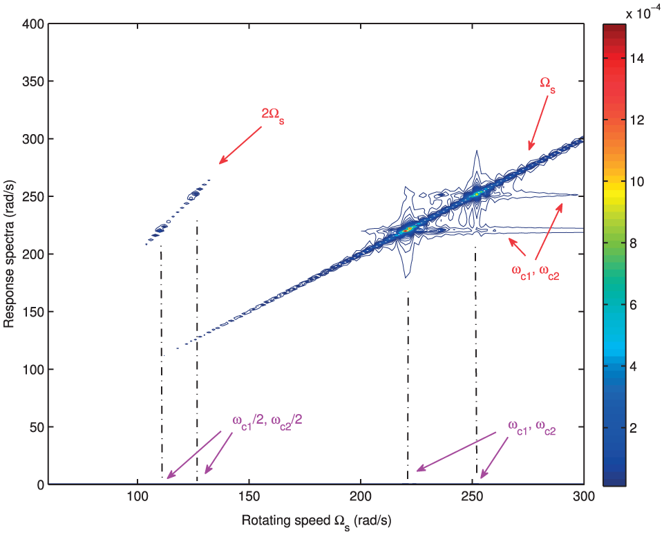
Without base movements, the contour plot of the steady-state response (x-direction of node 3) for the asymmetric rotor system is presented in Figure 6. One can see that the response spectra mainly contain the rotating speed and its integral multiples and natural frequencies . It is known that the spectral amplitudes of would be attenuated gradually with time in damped systems except for the resonant system. Besides the backward and forward critical resonances , the rotating speed equal to half of the critical speeds would also lead to the external resonances, as shown in Figure 6. This is due to the parametric stiffness excitation from shaft asymmetry.16
Contour plot of the steady-state response (x-direction of node 3) for the asymmetric rotor system without base movements.
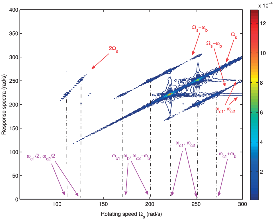
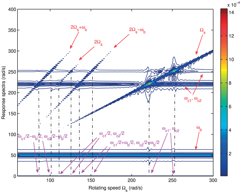
When the periodic pitching motion is considered ( and ), the contour plots of the steady-state response are given in Figures 7 and 8. Both the response spectra and external resonances are greatly changed after the pitching motion is considered. For the response spectra, besides and , there are also base frequency and combined frequencies between twice of rotating speed and base frequency, that is, . Increasing the pitching amplitudes makes these spectra more obvious, as shown in Figure 8. As long as the pitching motion is in operation, the spectra of natural frequencies become significant for the entire rotation speed range (see Figures 7 and 8). This indicates that the operation of pitching motion causes the transient response more severe and less likely to be weakened by damping.
Contour plot of the steady-state response (x-direction of node 3) for the asymmetric rotor system under periodic pitching motion ( and ).
Contour plot of the steady-state response (x-direction of node 3) for the asymmetric rotor system under periodic pitching motion ( and ).
Besides the critical and half-critical resonances, there are also multiple resonances around the half-critical resonances with the interval of half of base frequency . They could be expressed by and , as shown in Figures 7 and 8. This is the result of combined effects of the periodic pitching motion and shaft asymmetry. Also, increasing the value of makes the external resonances more distinct.
Rolling base motion is considered
For the operation of the periodic rolling motion ( and ), Figures 9 and 10 show the contour plots of the steady-state response. One can also find multiple response spectra in the dynamic response after the rolling motion is considered. Different with that of the pitching motion, the additional response spectra are around the rotation speed, that is, . Moreover, the spectrum of base frequency is not found and the amplitudes of natural frequencies are not as obvious as that of the pitching base–excited system. This indicates that the transient response would not be significantly excited by the periodic rolling base motion. Increasing the base amplitude from 0.1 rad to 0.2 rad not only causes the current spectra more distinct, but also induces more spectra around the rotation speed and twice of rotation speed. They are identified by and , as shown in Figure 10.
Contour plot of the steady-state response (x-direction of node 3) for the asymmetric rotor system under periodic rolling motion ( and ).
Contour plot of the steady-state response (x-direction of node 3) for the asymmetric rotor system under periodic rolling motion ( and ).
The periodic rolling motion also induces multiple external resonances besides the critical and half-critical resonances. However, different from that of the pitching base–excited system, the additional resonances of rolling base–excited system are around the critical resonances with the interval of base frequency . They are identified by and . It is noted that the resonance of is greater than 300 rad/s, and thus, it is not marked in the Figures 9 and 10. Moreover, the increase in base amplitudes more obviously leads to the external resonances.
Yawing base motion is considered
When the periodic yawing motion is considered ( and ), the results are shown in Figures 11 and 12. One can find that both the response spectra and external resonant characteristics are similar with that of pitching base–excited system. The response spectra are summarized as , (which are also found in asymmetric system), and . The multiple external resonances are expressed as , (which are also found in asymmetric system), and . Similarly, increasing the base amplitude causes both the response spectra and additional resonances more distinct.
Contour plot of the steady-state response (x-direction of node 3) for the asymmetric rotor system under periodic yawing motion ( and ).
Contour plot of the steady-state response (x-direction of node 3) for the asymmetric rotor system under periodic yawing motion ( and ).
Conclusion
Dynamic response characteristics of asymmetric rotor systems under time-periodic base angular motions are studied numerically in this article. As long as the periodic base angular motion is considered, both the response spectra and external resonances change significantly.
For the pitching or yawing motion in operation, additional frequencies, including base frequency and combined frequencies between twice of rotating speed and base frequency, are found in the dynamic response. The spectra of natural frequencies become significant for the entire rotation speed range, indicating that the operation of pitching or yawing motion causes the transient response more severe and less likely to be weakened by damping. When the periodic rolling motion is considered, the additional spectra observed in the dynamic response are the combined frequencies between the rotation speed and base frequency, which are different from that of the pitching or yawing base-excited system. In addition, the base frequency does not exist in the response, and natural frequencies are not obvious.
Besides the critical and half-critical resonances (which are found in the asymmetric rotor system), there are multiple resonances after considering the periodic base motions. For the pitching or yawing base–excited system, the multiple resonances are around the half-critical resonances with the interval of half of base frequency. However, when the rolling motion is in operation, the multiple resonances are found in the vicinity of critical resonances, and the interval is base frequency.
Footnotes
Handling Editor: Chenguang Yang
Declaration of conflicting interests
The author(s) declared no potential conflicts of interest with respect to the research, authorship, and/or publication of this article.
Funding
The author(s) disclosed receipt of the following financial support for the research, authorship, and/or publication of this article: The research work described in this article was supported by the National Science Foundation of China under Grant No. 11472147 and the State Key Laboratory of Tribology under Grant No. SKLT2015B12.
References
1.
SmithDM. The motion of a rotor carried by a flexible shaft in flexible bearings. P Roy Soc A: Math Phy1933; 142: 92–118.
2.
CrandallSHBrosensPJ. On the stability of rotation of a rotor with rotationally unsymmetric inertia and stiffness properties. J Appl Mech: T ASME1961; 83: 567–570.
3.
YamamotoTOtaH. On the unstable vibrations of a shaft carrying an unsymmetrical rotor. J Appl Mech: T ASME1964; 31: 515–522.
4.
YamamotoTOtaHKonoK. On the unstable vibrations of a shaft with unsymmetrical stiffness carrying an unsymmetrical rotor. J Appl Mech: T ASME1968; 35: 313–321.
5.
IwatsuboTTomitaAKawaiIR. Vibrations of asymmetric rotors supported by asymmetric bearings. Ing Arch1973; 42: 416–432.
6.
ArdayfioDFrohribDA. Instabilities of an asymmetric rotor with asymmetric shaft mounted on symmetric elastic supports. J Eng Ind: T ASME1976; 98: 1161–1165.
7.
WettergrenHLOlssonKO. Dynamic instability of a rotating asymmetric shaft with internal viscous damping supported in anisotropic bearings. J Sound Vib1996; 195: 75–84.
8.
IkedaTMurakamiS. Dynamic response and stability of a rotating asymmetric shaft mounted on a flexible base. Nonlinear Dynam1999; 20: 1–19.
9.
HanQKChuFL. Parametric instability of a Jeffcott rotor with rotationally asymmetric inertia and transverse crack. Nonlinear Dynam2013; 73: 827–842.
10.
KangYLeeYGChenSC. Instability analysis of unsymmetrical rotor-bearing systems using the transfer matrix method. J Sound Vib1997; 199: 381–400.
11.
KangYLeeYG. Influence of bearing damping on instability of asymmetric shafts—part III: disk effects. Int J Mech Sci1997; 39: 1055–1065.
12.
HsiehSCChenJHLeeAC. A modified transfer matrix method for the coupled lateral and torsional vibrations of asymmetric rotor-bearing systems. J Sound Vib2008; 312: 563–571.
13.
GentaG. Whirling of unsymmetrical rotors: a finite element approach based on complex co-ordinates. J Sound Vib1988; 124: 27–53.
14.
KangYShihYPLeeAC. Investigation on the steady-state responses of asymmetric rotors. J Vib Acoust1992; 114: 194–208.
15.
HanQKChuFL. The effect of transverse crack upon parametric instability of a rotor-bearing system with an asymmetric disk. Commun Nonlinear Sci2012; 17: 5189–5200.
16.
OncescuFLakisAAOstiguyG. Investigation of the stability and steady state response of asymmetric rotors, using finite element formulation. J Sound Vib2001; 245: 303–328.
17.
NandiANeogyS. An efficient scheme for stability analysis of finite element asymmetric rotor models in a rotating frame. Finite Elem Anal Des2005; 41: 1343–1364.
18.
LazarusAPrabelBCombescureD. A 3D finite element model for the vibration analysis of asymmetric rotating machines. J Sound Vib2010; 329: 3780–3797.
19.
LinFMengG. Study on the dynamics of a rotor in a maneuvering aircraft. J Vib Acoust2003; 125: 324–327.
20.
LeeASKimBOKimYC. A finite element transient response analysis method of a rotor-bearing system to base shock excitations using the state-space Newmark scheme and comparisons with experiments. J Sound Vib2006; 297: 595–615.
21.
DriotNLamarqueCHBerliozA. Theoretical and experimental analysis of a base-excited rotor. J Comput Nonlin Dyn2006; 1: 257–263.
22.
DucheminMBerliozAFerrarisG. Dynamic behavior and stability of a rotor under base excitation. J Vib Acoust2006; 128: 576–585.
23.
DriotNLamarqueCHBerliozA. Dynamics of a rotor subjected to a base translational motion and an uncertain parametric excitation. In: Proceedings of the 12th IFToMM world congress, Besançon, 18–21 June 2007. Amsterdam, Netherlands: Elsevier Publishing Group.
24.
El-SaeidyFMASticherF. Dynamics of a rigid rotor linear/nonlinear bearings system subject to rotating unbalance and base excitations. J Vib Control2010; 16: 403–438.
25.
SahaAGhoshRNandiAet al. Unbalance response analysis of a spinning rotor mounted on a processing platform. In: GuptaK (ed.) IUTAM symposium on emerging trends in rotor dynamics (IUTAM book series 25). Dordrecht: Springer, 2011, pp.135–142.
26.
LinFMengGHahnE. Nonlinear dynamics of a cracked rotor in a maneuvering aircraft. Appl Math Mech2004; 25: 1139–1150.
27.
JingJPLiJZLiuXQet al. Nonlinear dynamical behaviors of a cracked turbocharger rotor system with base excitation. Int J Nonlin Sci Num2009; 10: 563–580.
28.
YangYRenXQinW. Analysis on the nonlinear response of cracked rotor in hover flight. Nonlinear Dynam2010; 61: 183–192.
29.
HanQKChuFL. Dynamic response of cracked rotor-bearing system under time-dependent base movements. J Sound Vib2013; 332: 6847–6870.
30.
HouLChenYCaoQ. Nonlinear vibration phenomenon of an aircraft rub-impact rotor system due to hovering flight. Commun Nonlinear Sci2014; 19: 286–297.
31.
MarxSNatarajC. Suppression of base excitation of rotors on magnetic bearings. Int J Rotat Mach2007; 2007: 91276-1–91276-10.
32.
DasASDuttJKRayK. Active vibration control of unbalanced flexible rotor–shaft systems parametrically excited due to base motion. Appl Math Model2010; 34: 2353–2369.
33.
DasASDuttJKRayK. Active vibration control of flexible rotors on maneuvering vehicles. AIAA J2010; 48: 340–353.
34.
FriedmannPHammondEWooTH. Efficient numerical treatment of periodic systems with application to stability problems. Int J Numer Meth Eng1977; 11: 1117–1136.
35.
NayfehAHMookDT. Nonlinear oscillations. New York: John Wiley & Sons, 1979.