
Abstract
A novel Hydraulics AddiDrive System consisting of a variable displacement pump and two in-wheel motors is presented. The new Hydraulics AddiDrive System installed on the front axle of a traditional rear-wheel drive heavy vehicle aims to offer better mobility and improve traction efficiency in rough driving condition. To synchronize speeds between front in-wheel motors and rear wheels for optimal traction efficiency, a speed synchronization controller composed of feedforward and feedback control strategy is proposed for displacement adjustment of the variable displacement pump. The feedforward strategy is designed based on the relationship between the displacement coefficients of variable displacement pump and the gears. The feedback strategy utilizes proportional–integral algorithm to correct the dynamic errors. The compound speed synchronization controller helps to improve the control accuracy and adaptability under varied external conditions. Simulations are conducted on AMESim and MATLAB/Simulink to validate the proposed control strategy. The hardware-in-the-loop test allows for a more realistic evaluation of the proposed strategy, providing guidance of its application in real vehicle. Simulation and experiment results indicate that the maximum gradeability and traction force can be separately increased by 14.4%–17.2% and 13.4%–15.6% at low adhesion coefficient roads. The speed of front and rear wheel can be matched accurately with small difference below 1.31%.
Keywords
Introduction
Traditional rear-wheel drive heavy vehicle may slip and encounter insufficient traction when driving on low adhesion roads or other rough terrains. 1 To satisfy the desire of better mobility and high traction efficiency, two solutions were generally proposed, namely, mechanical all-wheel drive (MAWD) 2 and electric-assisted drive (EAD). 3 The MAWD widely applied in off-load vehicles has complex mechanical structure, leading to excessive weight and low efficiency. Additionally, the fuel economy of all-wheel drive (AWD) vehicle cannot hold a candle to the rear-wheel vehicle when driving in good roads. The EAD, changing the vehicle front non-driving wheels to auxiliary drive wheels, simplifies the structure and reduces the gross weight.4,5 But the battery has shortcomings of expensiveness and short lifetime. 6
The paper presents a new Hydraulics AddiDrive System (HADS) consisting in an additional hydrostatic transmission. 7 The HADS overcomes the shortcomings of traditional rear-wheel drive vehicle. It can effectively use the vehicle’s own weight to get the maximum traction and improve its performance on rough road significantly. Compared with MAWD, the HADS can be started on-demand, switching from rear-wheel drive to AWD by actuating the in-wheel motors installed in front wheels and turned off when the vehicle drives on good roads in order to improve traction efficiency and reduce fuel consumption. The structure of HADS can be greatly simplified by the hydrostatic transmission characterized as high power density, small size, and light weight. Besides, the variable displacement pump (VDP) and the hydraulic control valves have the advantages of precise control and fast response, 8 and the radial piston hydraulic motor can achieve high torque at low speed. Overall, the HADS has more advantages and good application prospects in heavy vehicle market. 9
The performance of the HADS about offering better mobility and improving traction efficiency depends on the speed synchronization control strategy (SSCS). According to the theory of ground vehicles, 10 the AWD vehicles reach the maximum traction efficiency in straight driving when the speed of the front driving wheels and the rear driving wheels equal to each other. Thus, the core of the SSCS lies in the displacement control of the VDP, which decides the speed of the front wheels through adjusting the swash-plate angle of the VDP. 11 The changing driving conditions demand that the VDP displacement should be controlled in real time to meet actual load requirements.12–15 An optimum slip ratio–based proportional–integral–derivative (PID) control algorithm was proposed to adjust the displacement of VDP. 16 Simulation results show that the trafficability of vehicle is significantly improved on low adhesion coefficient roads. However, it lacks sufficient self-adaptability 17 to work perfectly under variable driving conditions and the traction efficiency of vehicle was not considered. Do et al. 18 designed an adaptive fuzzy sliding mode controller to control the velocity of secondary control units, such as VDP by adjusting its displacement in a secondary controlled hydrostatic transmission system. Although test results showed that the proposed controller was excellent from the standpoints of performance and stability for velocity control, 18 it was easy to produce wrong operation when malfunction was happened. Hasan et al. 19 presented a negative feedback proportional–integral (PI) control of pump displacement to attain desired speed of hydro motor in the hydrostatic transmission system under varying load conditions. It is validated that the motor speed can track the desired value. The pressure control of self-supplied axial piston VDP was proposed to deal with the problem of fast changing and unknown loads by Kemmetmüller et al. 20 A nonlinear 2-degree-of-freedom control strategy in combination with a load estimator is introduced for the pressure control. 21 The simulation results show an excellent and robust behavior. However, although the control strategies for pump displacement in the above literatures have achieved very good results, they lack the consideration of the impact on vehicle performance.
Previous studies have made important contributions in terms of proposing various control strategies for the displacement control of the VDP. However, there are some shortcomings in the previous control algorithms, including insufficient adaptability, poor reliability, and no comprehensive consideration of the impact of the algorithm on vehicle performance. In addition, the publications of the displacement control of the VDP devoted to HADS are rather scarce. Therefore, as for HADS researched in the paper, these previous control algorithms do not apply to the system and a feasible control algorithm which plays an advantage in production vehicles is needed. Derived from previous research, in this study, a compound wheel speed controller composed of feedforward and feedback control strategy is designed for displacement adjustment of the VDP. Through the feedforward controller based on the method of look-up table, constant values of VDP displacement are obtained corresponding to different gears. The feedforward controller realizes the rapidity and stability of the control process. The function of feedback controller based on the idea of PI algorithm is to correct speed deviation caused by external factors such as oil leakage and temperature variation. The compound control is used to ensure the precision of wheel speed synchronization. Then, the proposed speed synchronization controller is validated on the offline platform. Besides, hardware-in-the-loop (HIL) test plays an important role in verifying the feasibility of the algorithm in the development of vehicle control system. Thus, the compound control strategy is finally validated in HIL so as to guide the application on the real vehicle.
The paper is organized as follows: section “System modeling” presents the system configuration and dynamic mathematical models of the HADS system in detail. Section “SSCS” introduces the control strategy design. Simulation analysis and HIL experiment analysis are described in section “Simulation and experiment analysis.” The conclusion is given in section “Conclusion.”
System modeling
System configuration
As shown in Figure 1, the novel HADS is added to a traditional heavy vehicle with the engine, clutch, gearbox, and transmission shaft. The hydraulic system is composed of two hydraulic in-wheel motors, a VDP, the hydraulic control valve group, 22 and the hydraulic control unit (HCU). The power take-off (PTO) is mounted on the engine’s power output and delivers power to the VDP. The VDP is connected to the two hydraulic in-wheel motors through hydraulic tubing to constitute a hydraulic transmission circuit. The hydraulic control valve group connects or partitions different hydraulic transmission circuits according to the system requirements of different working conditions. The hydraulic motors are installed in front wheels to directly drive the vehicle. And the HCU establishes communication and control between the system and the vehicle.
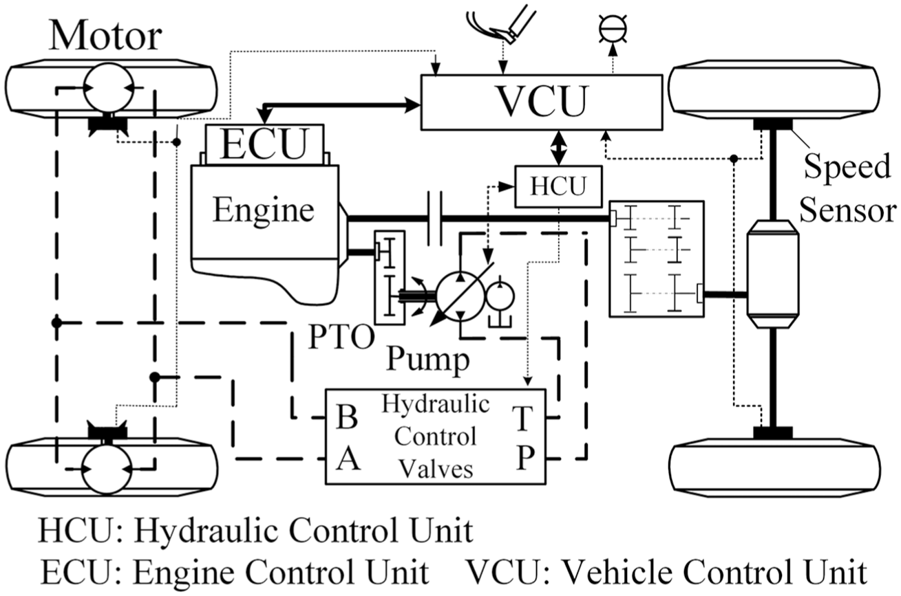
System configuration.
Dynamics modeling
Dynamics modeling of the HADS contains traditional mechanical transmission and hydraulic transmission models. The construction of dynamics mathematical models helps to research on working ways and driving characteristics of AddiDrive system.
Modeling of traditional drivetrain
The article mainly focuses the effect of proposed speed control applied in the HADS; therefore, the engine model is expressed by a first-order kinetic equation

where Ie is the inertia moment of engine crane and clutch driving disk,
The engine output torque Te can be simplified as the function of engine angular speed

The part of power transmission which begins from clutch-driven disk and ends in rear axle is regard as a whole. The angular speed
23
of the clutch-driven disk and gearbox input shaft

where Mbr is the brake torque of wheel, Fxr is the output traction force of rear wheels, Fzr is the vertical load of rear wheels, f is the coefficient of rolling friction between wheel and road, R is the wheel radius,
Therefore, the rear wheel angular speed

And, the wheel slip ratio sxw can be calculated by

where v is the instantaneous velocity of the vehicle.
The traction force of the rear axle Fxr can be inferred by

where
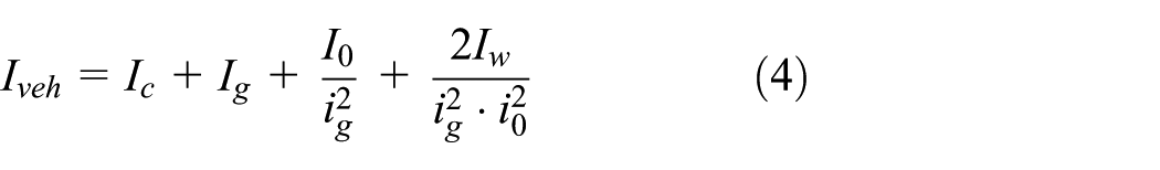
The vehicle driving equation is

where Ff is the vehicle rolling resistance, Fw is the vehicle air resistance, Fi is the vehicle grade resistance, and Fj is the vehicle acceleration resistance.
Modeling of hydraulic components
As shown in Figure 1, the hydraulic pump acquires power through PTO; the relationship between angular speed of the pump and the engine can be described as

where iPTO is the gear ratio of the PTO and
The displacement of the VDP is controlled by a servo proportional valve and a double-acting hydraulic cylinder.24,25 Considering the steady charging pressure of slippage pump, the inlet pressure of servo proportional valve can be considered as constant. The servo proportional valve can be simplified as a second-order oscillation system as follows


where Qsv is the flow of servo proportional valve, Isv is the current of servo proportional valve, Ksv is the flow gain of servo proportional valve, qR is the rated flow of servo proportional valve, iR is the rated current of servo proportional valve,
The flow continuity equation of the hydraulic cylinder can be described by

where Qc is the flow of hydraulic cylinder, Ac is the effective working area of hydraulic cylinder, Ctc is the total leak coefficient of hydraulic cylinder, Vtc is the total working capacity of hydraulic cylinder,
The motion equilibrium equation of the piston in hydraulic cylinder can be mathematically formulated as follows

where mc is the total mass of piston in the hydraulic cylinder, bc is the viscous damping coefficient of piston in the hydraulic cylinder, and kc is the stiffness of return spring in the hydraulic cylinder.
According to equations (12) and (13), the whole mathematic model of hydraulic cylinder can be inferred as follows
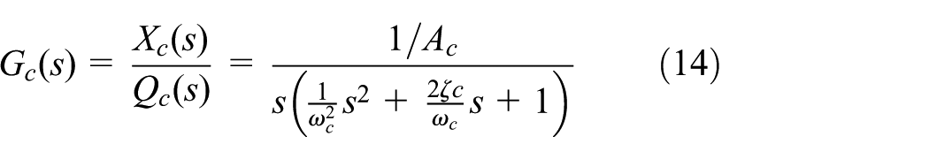


where
Therefore, the displacement signal

where
Then the torque equilibrium equation of hydraulic pump can be derived by

where
And the output flow 26 of the VDP can be described as follows

where Cp is the leak coefficient of hydraulic pump.
Supposing that the flow and pressure losses of pipes and hydraulic control valves are fairly little, and both the motors have equal flow from the pump. Therefore, the angular speed of each motor is calculated as follows

where
Then the torque equilibrium equation of constant displacement motor can be inferred by

where Jm is the inertia moment of in-wheel motor rotor shaft, Bm is the damping coefficient of in-wheel motor rotor shaft, Mbf is the brake torque of front wheels, Fzf is the axle load of front wheels, and Fxf is the traction force of front wheels.
SSCS
According to the motion theory of ground vehicles,
27
the slip efficiency

where sf, sr represent the slip rate of front wheels and rear wheels, respectively;
To obtain the maximum slip efficiency, seeking the first-order partial derivative of

Note that only if sf or sr is equal to 100%, or sf and sr are equal, the equation is true. Clearly, when sf or sr is equal to 100%, the vehicle cannot move at all. Thus, the optimal slip efficiency can be obtained only when the slip rates of the front and rear wheels are the same, that is, the speeds of the front and rear wheels are equal since the tires are consistent. Otherwise, the speed difference of front and rear wheels will cause parasitic power, which greatly reduces the traction efficiency. Therefore, a controller combining the feedforward and feedback strategy is proposed to synchronize the speed of the front and the rear wheels by adjusting the displacement of the VDP.
Feedforward control strategy
When the HADS operates, the target angular speed of the front in-wheel motors

where
According to the liquid flow continuity equation, the relationship between pump and motors in flow can be described as the following formula

where np is the rotational speed of pump and nm is the rotational speed of in-wheel motors.
Therefore, the displacement coefficient of the VDP can be calculated by
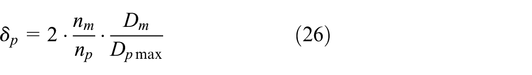


According to equations (26)–(28), the target displacement coefficient can be inferred as

As is known in equation (29),
Relationship between the displacement coefficients of VDP and the gears.

VDP: variable displacement pump.
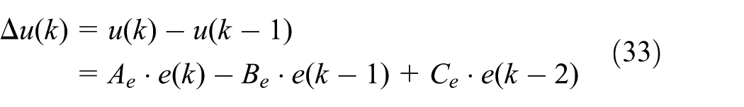
The simulation result of the feedforward control is shown in Figure 2; it suggests that the front wheel speed can track rear wheel speed in both first gear and second gear when it is only controlled by the feedforward controller, which reflects the advantages of fast response and multi-condition adaptability. However, there also exists speed difference between the front and rear wheels, which will negatively impact the traction efficiency. Thus, a further improvement which can reduce the speed steady-state error with feedback control method is needed.

Speed curves of front and rear wheels.
Compound control strategy
There is still a small gap between front and rear wheel speed because of the leaks and spills in the hydraulic components which are hardly predictable. The feedforward controller, also called open-loop control system, fails to eliminate errors caused by external disturbances. The feedback controller can significantly improve the accuracy based on error control. Thus, a feedback controller based on PI algorithm is applied to correct the displacement coefficient

And the PID control algorithm 17 in continuous control system can be defined as

The discretized PID algorithm can be described as
Furthermore, in order to reduce the variation effect of control parameter, the incremental PID algorithm is proposed as


where kp is the gain of PID algorithm, Ti is the integral parameter of PID algorithm, and Td is the differential parameter of PID algorithm.
Finally, the displacement coefficients output by the compound controller are described as

where
The structure of the compound controller is given in Figure 3, where the actuator refers to the servo proportional valve and hydraulic cylinder of pump and the control object refers to the HADS response system.

Compound control algorithm.
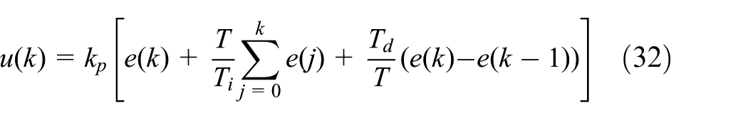
The simulation results based on a feedforward and feedback controller with different parameters kp and Ti are shown in Figure 4.
Front and rear wheel speed curves of different PID parameters: (a)
The parameter kp reduces the wheel speed gap at the beginning 3 s, but it needs much time to eliminate the speed gap and the speed fluctuation of front wheels. The parameter Ti can greatly compress the time of eliminating the speed gap, without obviously reducing the rear wheel speed at the beginning 3 s. Figure 4(a) shows that the front wheel speed has a periodic fluctuation due to the too large value of kp. But the fluctuation decreases greatly after diminishing kp, as shown in Figure 4(b). The values of Ti and kp in Figure 4(c) are appropriate and the front wheel speed can track the rear wheel speed perfectly. As shown in Figure 4(d), the value of kp is too small and Ti is too large; the front and rear wheels are not synchronized. Finally, the optimum PID parameters are listed in Table 2. Compared with feedforward controller, the dynamic response is better improved by compound-loop controller.
PID parameter.

PID: proportional–integral–derivative.
Simulation and experiment analysis
In this section, the validity of the compound controller is tested by offline simulation with models built in AMESim and MATLAB/Simulink. In addition, for better application in real vehicle and reducing the experiment cost, the HIL method is adopted to verify the control algorithm.
Offline simulation and analysis
The heavy vehicle and hydraulic system parameters are gathered in Table 3. Figures 5 and 6 are AMESim model and Simulink model, respectively. The data exchange is achieved by S-function. The simulation of vehicle starting and accelerating process and the simulation of tractive performance are performed as follows.
Vehicle and hydraulic system parameters.


AMESim model.

Simulink model.
Simulation of vehicle starting and accelerating process
The compound controller which combines the feedforward control strategy and the feedback control strategy is tested on the above offline simulation platform. The road adhesion coefficient is supposed as 0.4 and vehicle starts from standstill during first gear. Then the simulation results are analyzed.
As shown in Figure 7, the wheel speeds gradually rise from zero and eventually stabilize, indicating that the vehicle can be started normally on a low adhesion road. During the first 2 s, due to the clutch slippery, the engine speed and rear speed have not yet reached the speed ratio, there is a difference between the front and rear wheel speed. But 2 s later, the clutch is fully integrated and the engine speed and rear wheel speed reach a certain ratio, so the speed of the front and rear wheels quickly reach the same.
Front and rear wheel speed curves.
The wheel traction curves are presented in Figure 8. The front wheel traction indicates that the front wheels turn to driving wheels from driven wheels and drive the vehicle forward with the rear driving wheels together. At the beginning of the vehicle start, the required traction is large. As the speed stabilizes, the front and rear wheel output traction decrease and stabilize gradually. Figure 9 shows the displacement coefficients of the VDP under the first gear. Due to the wheel speed difference at the beginning 2 s, the displacement has a small overshoot. Then the displacement signal of VDP is rapidly maintained at around 0.3, which reflects the speediness of the feedforward controller and the accuracy of the feedback controller.
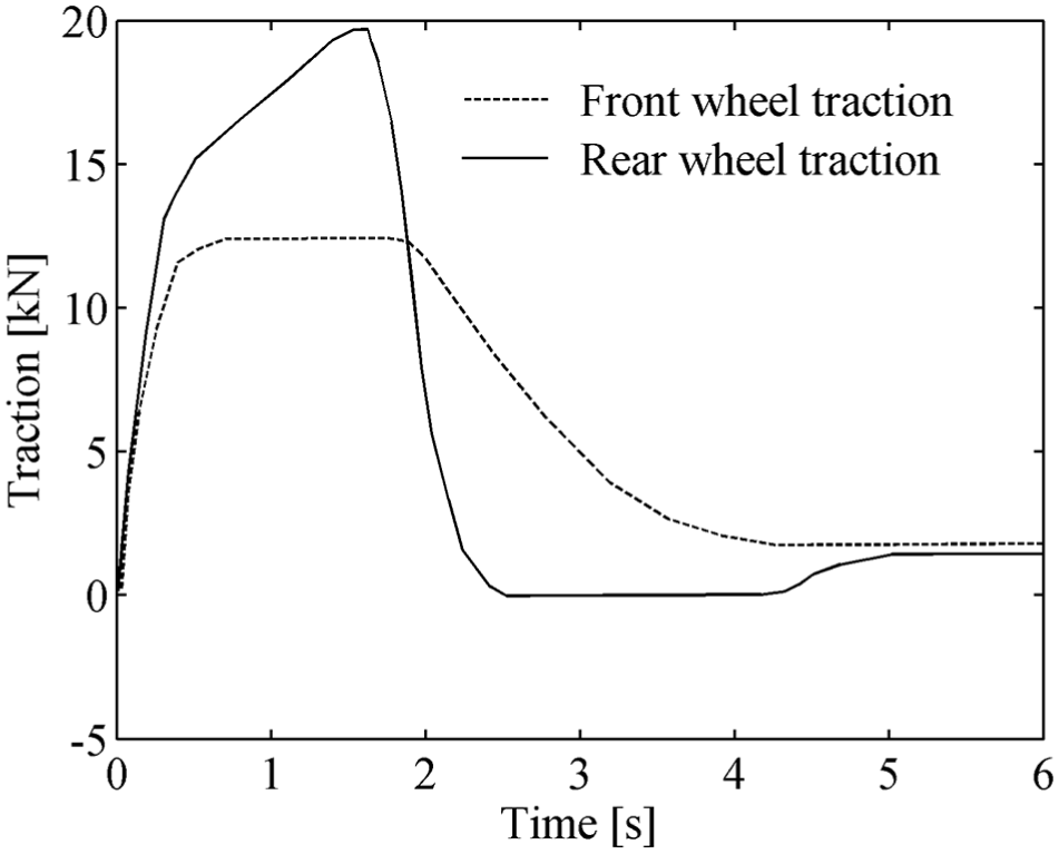
Wheel traction curves.
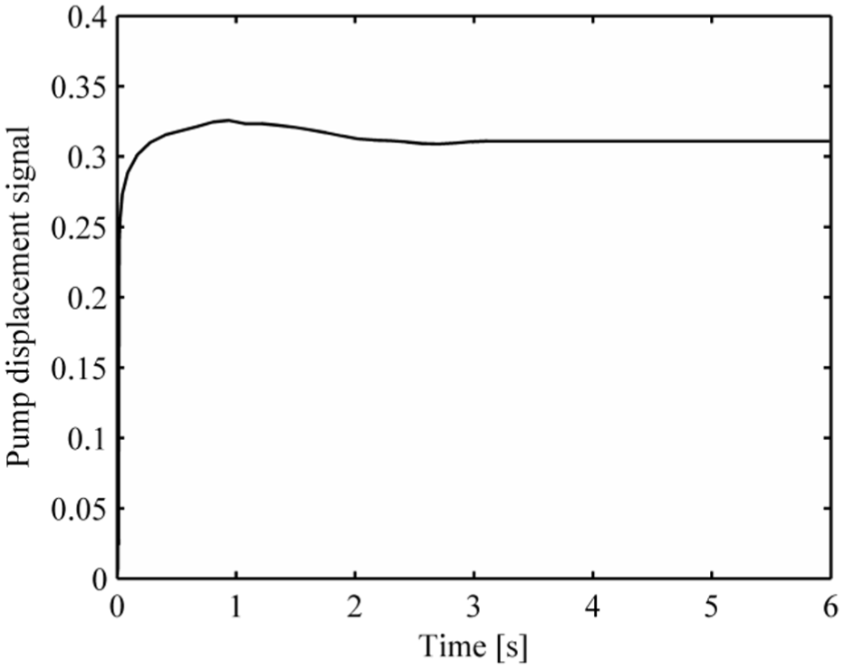
Pump displacement coefficient.
Figures 10 and 11 depict the flow and outlet oil pressure of pump, respectively. And the output torque of the motors is controlled to adapt the load on the front wheels, as shown in Figure 12. The pump flow has a small overshoot at about 1 s. In the beginning 2 s, the vehicle needs a large amount of power to start from standstill. Therefore, the pump outlet pressure and the motor torque increase rapidly. With the stability of speed, the pump pressure and the motor torque decrease because the required torque decreases.

Pump flow.

Pump outlet pressure.
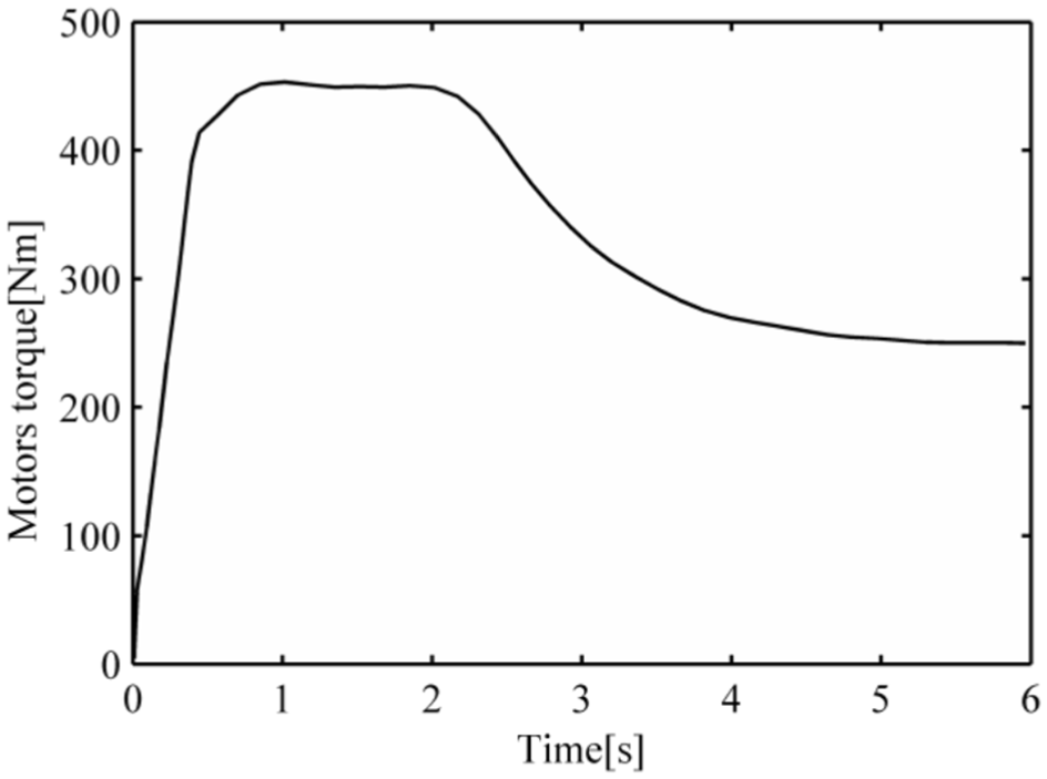
Hydraulic motor torque.
From the above analysis, we can see that the displacement of pump can be quickly and precisely controlled after using the compound controller. The front wheel speed can perfectly track the rear wheel speed with small overshoot, as shown in Figure 7. As shown in Figures 8–12, the control effect of compound controller is smooth and stable, which improves control quality of hydraulic system.
Simulation results of tractive performance
In order to compare the tractive performance before and after using HADS under different situations, the road slope gradually increases from 0 when the road adhesion coefficient
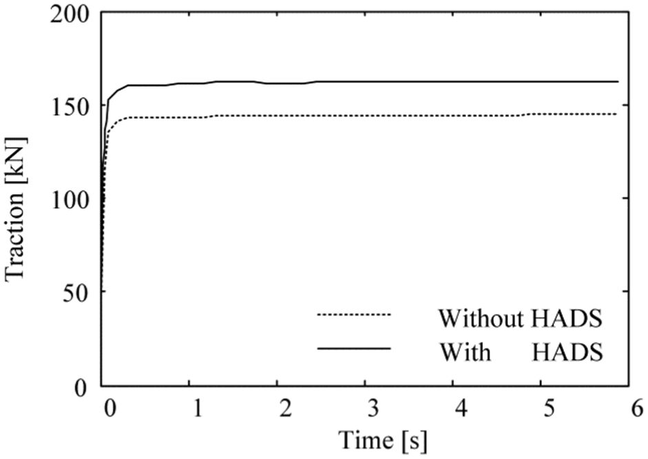
Traction curves on the simulation of tractive performance.
Table 4 compares the maximum traction force and climbing grade before and after applying HADS when
Simulation results comparison.
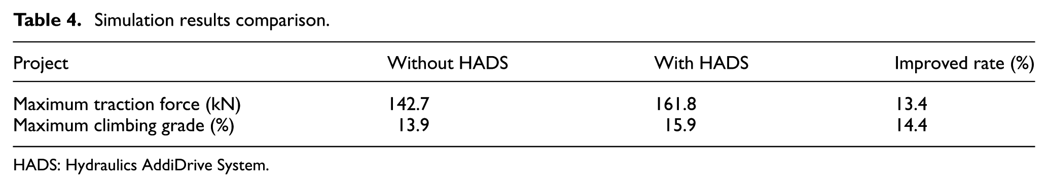
HADS: Hydraulics AddiDrive System.
Figures 14 and 15 present the maximum traction force and climbing grade with different

Maximum traction comparison.

Maximum climbing grade comparison.
HIL experiment and analysis
In the development of automotive control systems, the HIL experiment has the advantages of experimental repeatability, the ability to simulate special fault in practice and studying different algorithms on the dynamic characteristics of the controller, and so on. Therefore, the HIL experiment is performed in this part to test the proposed compound control strategy. A TTC200 controller following the IEC 61508 international standards and a simulator for virtual driving environment are used in the HIL experiment. As shown in Figure 16, the hydraulic system model built in AMESim and the traditional vehicle model established by MATLAB/Simulink 28 are downloaded to the simulator. The speed controller model built in MATLAB/Simulink is downloaded to the TTC200 controller. Real-time communications between the controller and simulator are established to transmit the control signals and the components working status through Controller Area Network (CAN) bus. 29 The given road adhesion coefficient is set to 0.4. The test of the vehicle starting process is completed during first gear.

Platform of hardware-in-the-loop.
Sudden acceleration simulation on a flat road
The vehicle accelerates at 100% throttle position from standstill on a flat road under the HIL simulation platform. As shown in Figure 17, the variation of wheel speeds is smooth and the gap between the front and rear wheel speeds is small, which suggests the controller is stable and has a high degree of accuracy. The trend of engine speed fits the rear wheel speed as shown in Figure 18. The engine speed reaches the maximum speed rapidly and steadily with the sudden acceleration.

Wheel speeds on sudden acceleration simulation.
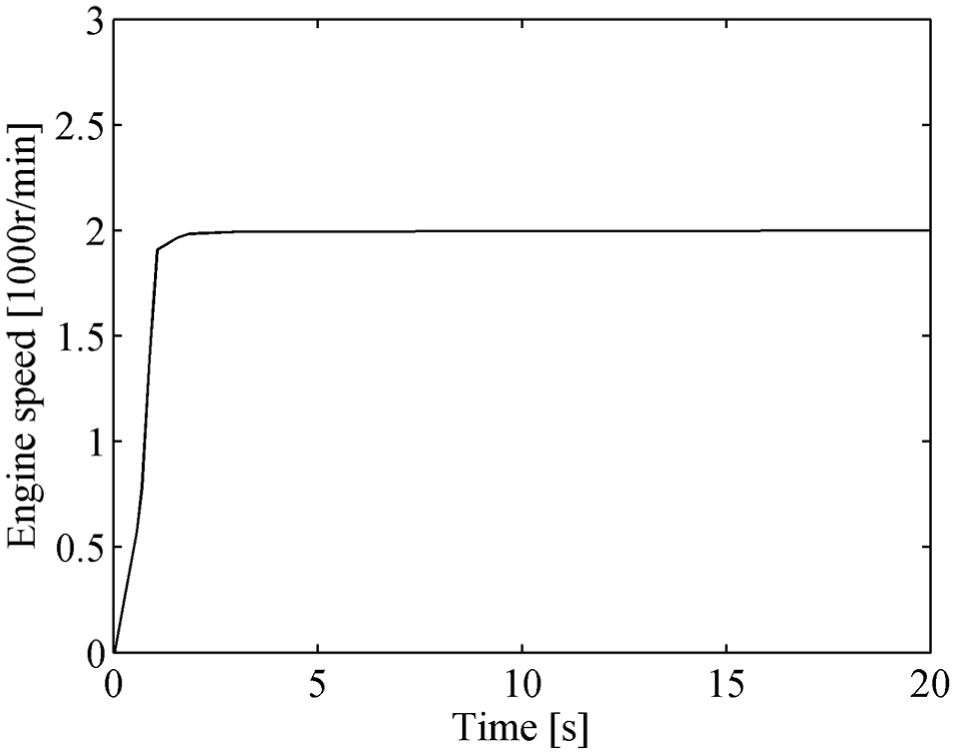
Engine speed on sudden acceleration simulation.
Figure 19 shows the pump displacement signal. Due to no transmission shift, the displacement signal of VDP is maintained at around 0.3. Figure 20 shows the front and rear wheel traction curves. The front and rear wheels are both driving wheels and provide the traction together. The traction drops as the speed becomes stable. From the above analysis, the desired pump displacement signal is able to be reached with no big fluctuation and the wheel speeds are synchronized well under the sudden acceleration simulation, which demonstrates the robustness of proposed control algorithm.

Pump displacement signal on sudden acceleration simulation.

Traction curves on sudden acceleration simulation.
Simulation on a variable gradient pavement
At the beginning, the vehicle is driven on a flat road during first gear. The climbing grade increases to 8% by a step-input signal at around the fourth second.
Figure 21 shows the variation of the engine speed. Due to the increase of climbing grade, the vehicle driving resistance is on the rise. Therefore, the engine speed decreases to obtain a bigger output torque. Correspondingly, the vehicle velocity and wheel speed drop at the same time, as shown in Figures 22 and 23.
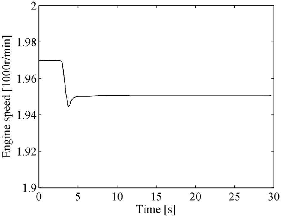
Engine speed on the simulation of a variable gradient pavement.

Vehicle velocity.

Wheel speeds on the simulation of a variable gradient pavement.
From Figure 23, we can see that there is a little speed difference between front and rear wheels because there exists flow leakage caused by the pressure loss and volume change of pipe in hydraulic circuits. As shown in Figure 24, the displacement signal of VDP is gradually arrived at around 0.3.

Pump displacement signal on the simulation of a variable gradient pavement.
From traction curves in Figure 25, we can see that the front and rear wheel traction possess the similar variation tendency with a small deviation at about 5 s. The designed controller proves to have good accuracy and adaptability.

Traction curves on the simulation of a variable gradient pavement.
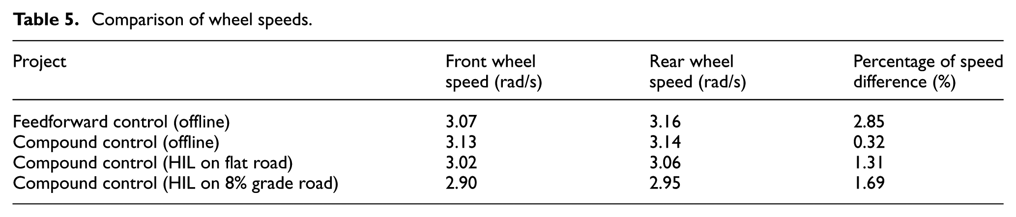
Table 5 compares the percentage of wheel speed difference between front and rear wheels under different conditions. It shows that on offline, the speed difference of the compound control is 0.32%, while the feedforward control is 2.85%, which proves that the compound control is more accurate than the feedforward control. On the HIL platform, the speed difference of the compound control on flat road is 1.31% and on 8% grade road it is 1.69%. The small speed difference shows good performance of the controller. The HIL simulation results prove the real-time reliability of the proposed algorithm. In comparison with the real vehicle test, the HIL platform has the advantages of convenience and high efficiency. Besides, the influence of dynamic factors is also considered in the HIL simulation and it is more truthful to reflect the real vehicle test than offline simulation.
Comparison of wheel speeds.
Conclusion
A speed synchronization controller is designed for the heavy vehicles with HADS to improve traction efficiency. Based on the idea that the front wheel speed follows the rear wheel speed, a new compound control strategy which combines feedforward control and feedback control is applied to the speed synchronization controller. The tests, including the offline simulation test with HADS model established by AMESim and vehicle components model built in MATLAB/Simulink and the HIL test, are applied to validate the proposed speed synchronization controller.
Results show that the maximum traction force and gradeability of the heavy vehicle with HADS are improved significantly with the designed speed controller. The front wheel speed can track the rear wheel speed with small speed difference below 1.31%. In this study, the feedforward controller guarantees the basic driving stability and the feedback controller improves the accuracy. The compound control is more accurate than the feedforward control. That is, the HADS not only improves the passing ability significantly, but also optimizes the vehicle traction efficiency obviously.
The study can aid the application of the novel HADS in the hydraulic hybrid vehicles thanks to the compound control methodology, which has a certain reference value for the development of control strategy of hybrid vehicle. Unfortunately, this study only examined the static characteristics of HADS. The influence of hydraulic dynamic performances on the transmission was not considered. Therefore, for future research, the dynamic performances of hydraulic circuit and other hydraulic components of HADS are expected to be taken into consideration.
Footnotes
Handling Editor: Sang-Wook Kang
Declaration of conflicting interests
The author(s) declared no potential conflicts of interest with respect to the research, authorship, and/or publication of this article.
Funding
The author(s) disclosed receipt of the following financial support for the research, authorship, and/or publication of this article: This work was supported by the National Natural Science Foundation of China (NSFC No. 51675214, 51575221), the science and technology development project Projects of Jilin Province, China (No. 20160519008JH), and the Graduate Innovation Research Project of Jilin University (No. 2016083, No. 2017127).