
Abstract
This research concerns a novel micro-ducted-fan aircraft. A structured attitude controller is designed for a novel unmanned aerial vehicle in the presence of strong state coupling and system perturbation. The novel unmanned aerial vehicle is equipped with two tandem ducted fans to provide the main thrust. Relative to conventional (open-rotor) aircraft, our novel unmanned aerial vehicle can perform much better in indoor or other complex conditions. The inherent advantages of the duct structure also make this type of unmanned aerial vehicle more compact and efficient. In this research, a structured multi-loop feedback attitude controller is employed based on H-infinity synthesis and tuned using a type of non-smooth optimization method. This non-smooth optimization method directly and efficiently tunes the proposed control parameters to ideal structures while ensuring satisfactory practical control performance. A series of computer simulations and basic flight experiments are applied to evaluate the performance of the proposed controller. The results of simulations and experiments confirm that the performance of the proposed attitude controller is reliable and efficient in practice.
Introduction
With the development of automatic flight control technologies, autonomous aircraft has become a focus of society and academic institutions. Until now, the most common unmanned aerial vehicles (UAVs) have had an open-rotor structure; however, this design may not satisfy the current requirements. The working environment and conditions are becoming increasingly challenging. For example, UAVs may be required to enter rooms indoors or operate in other complex indoor conditions instead of operating in open-air situations only. The inherent limitations of traditional open-rotor UAVs are expected to become an obstacle hindering further practical application. Here, we propose a novel tandem micro-ducted-fan UAV with strong potential in complex working conditions. The inherent advantages of the novel UAV are as follows.
Relative to a conventional rotor, a ducted fan can produce more thrust and provide higher overall efficiency at lower speeds. 1 Therefore, the ducted-fan UAV can be designed to be significantly more compact, making this configuration more flexible. For clear presentation, Table 1 shows a comparison between the aerodynamic effects of a ducted-fan UAV and an open-rotor UAV for three different scenarios. DR in Table 1 represents the rotor diameter of a conventional (open-rotor) UAV, T is the maximum thrust produced by a conventional UAV and Pi is the aerodynamic power consumed by a conventional UAV. Scenario 1 shows that relative to a conventional UAV, when producing the same thrust, the ducted-fan UAV requires a smaller rotor diameter while consuming the same aerodynamic power. A comparison with Scenario 2 indicates that the ducted-fan structure can produce more thrust (the additional thrust is produced by the duct) with the same rotor diameter while consuming the same aerodynamic power. From a comparison with Scenario 3, we find that when producing the same thrust with the same rotor diameter, the ducted-fan structure requires less aerodynamic power. In summary, the results of the comparisons indicate that the ducted-fan structure offers better performance via load capacity, body dimension and operation efficiency.
Aerodynamic effect comparison between open-rotor and ducted-fan UAVs.

Relative to a normal open-rotor UAV, the novel tandem dynamic layout of our UAV considerably decreases the safety area required for departure and landing, as shown in Figure 1. This characteristic makes the UAV more suitable for complex practical applications. In addition, the duct structure surrounds and protects the inside rotor from obstacles, which ensures excellent safety and effectiveness in indoor working conditions and complex outdoor environments. In summary, relative to conventional open-rotor aircraft, our UAV has inherent advantages when working indoors and in unknown or otherwise complex environments. The proposed advantages enable our novel UAV to perform well in both military and civilian applications, such as air transportation, high-voltage power-line inspection, disaster relief, complex environmental investigation and indoor anti-terrorism efforts.

Take-off safety area comparison between a tandem ducted-fan fly vehicle and a normal quad-rotor.
In a previous study by the Beijing Institute of Technology (BIT), our team presented a ducted-fan aircraft prototype with a vane control system. Research and simulations of this prototype were published elsewhere. 2 However, the experimental results of the prototype show poor stability in the rolling channel, which indicates a lack of control over the forces and moments. One of the primary contributions of the present study is an improved attitude control structure to exert greater control moments for the rolling channel. Figure 2 shows the structure of the revised UAV, which consists of two primary ducted fans, two auxiliary electric ducted fans and two tilting structures. The control system is based on a micro-carrier personal computer with a Linux operating system. The two primary rotors are used to provide the primary thrust. The speed difference between the two main ducts is used to provide pitch control moments. Similarly, the speed difference between the two auxiliary ducts is responsible for roll control moment generation. The angle difference between the two tilting structures is designed for yaw control moment generation. Relative to the previous prototype, the revised UAV is shown here to exhibit more effective attitude control performance through simulations and flight experiments.

Small-scale unmanned tandem ducted-fan vehicle.
Although the novel UAV has many advantages and improvements, a series of challenges are unavoidable in control system design. These problems are caused primarily by the sophisticated aerodynamics of the novel structure. In addition to the pitching moment (caused by the duct) making the UAV unstable, the new tilting structure leads to significant coupling between the attitude states. Moreover, the additional actuators increase the nonlinearity of the plant. Previous reports proposed several controllers for ducted-fan UAVs, including linear control methods and nonlinear control methods. For linear control methods, the classical proportional–integral–derivative (PID) control theory is adopted in Ko et al., 1 Pflimlin et al. 3 and Peddle et al.; 4 linear quadratic regulator (LQR) control theory and pole-placement control theory are studied in Shan et al. 5 and Muehlebach and D’Andrea, 6 respectively, and in Wang et al., 2 Avanzini et al. 7 and Xu et al., 8 classical robust control theory is applied. For nonlinear control theories, the model predictive method, 9 back-stepping technique 10 and neural network adaptive method 11 have been reported. However, constraints remain that are associated with these control methods and research. First, most of the controllers are applied to a single-ducted-fan UAV. For the complex multi-ducted-fan UAV proposed in this research, these controllers may not perform well. Second, most of the proposed research focuses only on the time-domain performance of the system and generally lacks specific frequency-domain analysis and robustness margins. Finally, the designed controllers follow the classical robust loop-shape control theory, and nonlinear control methods are always of high order, making these controllers challenging to apply in practice.
In our previous work, 8 a structured robust loop-shape controller was designed and studied. However, only a speed-loop was discussed in that study, and attitude state decoupling and tracking were not investigated in sufficient detail. Therefore, the control aim of the present research is to present a low-order attitude flight controller for the novel UAV that can provide satisfactory attitude decoupling ability and ensure tracking performance in practical applications. The controller is designed based on H-infinity synthesis and tuned using a non-smooth optimization (NSO) method. Basic flight tests are performed to verify that the proposed UAV employed by the designed attitude controller can achieve satisfactory performance. The attitude channel response to corresponding reference signals can settle within 2 s with reasonable overshoots and minimal steady errors.
The article is organized as follows: A simplified nonlinear dynamic model of the UAV is developed in section ‘Dynamic modelling’; in section ‘Structured attitude controller design’, a structured attitude feedback controller is designed, and the detailed procedure is presented. After a series of digital simulations, flight experiments are performed in section ‘Flight experiments’ to evaluate the closed-loop system performance. Then, the results of these tests are demonstrated and analysed.
Dynamic modelling
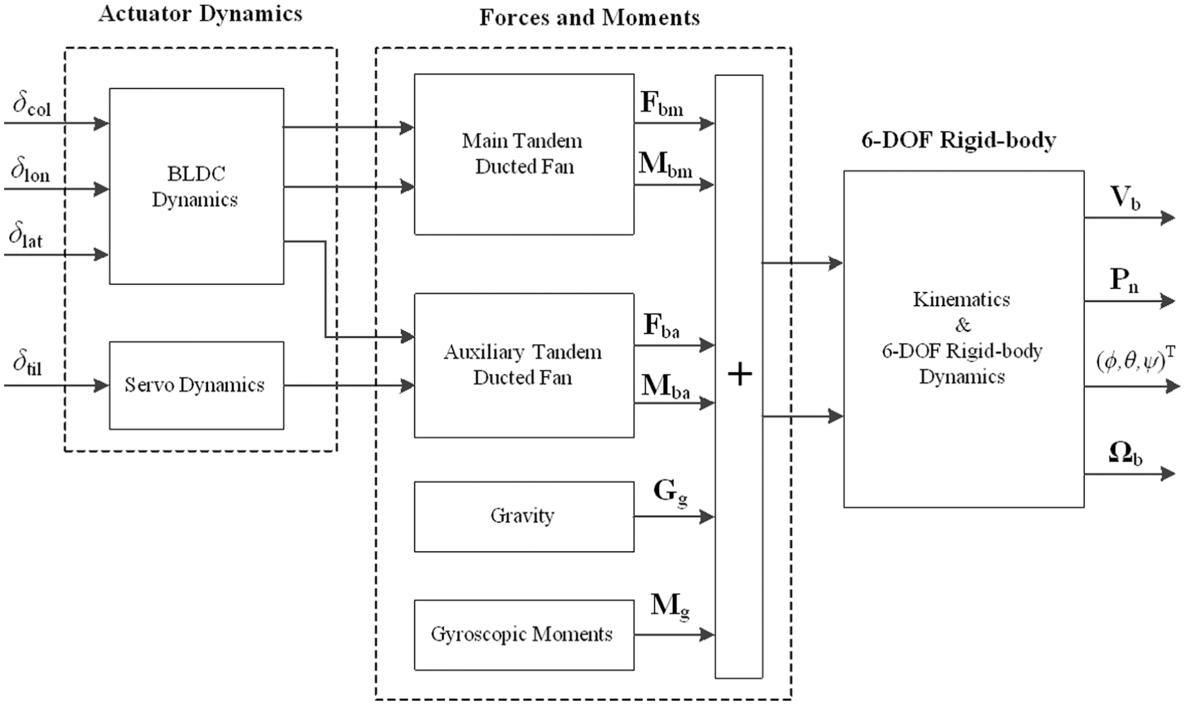
Dynamic modelling of the novel UAV is challenging mainly because (1) aerodynamic interference exists, including interference between the two primary ducted fans and interference between the two auxiliary ducted fans and (2) heavy state coupling and structural nonlinearity make the dynamic model particularly complex. However, an advanced automatic flight control system should be maintained using an accurate and reliable mathematical model. Therefore, in this section, a comprehensive control–oriented nonlinear model of our UAV is presented based on aeromechanical physical laws. The structure of the model is shown in Figure 3.
Tandem ducted-fan vehicle structure.
In this research, the UAV is considered a 6-degree-of-freedom (DOF) rigid body. In addition to the aerodynamics of the primary and auxiliary ducted fans, the actuator dynamics and gyroscopic moments are studied. The state and input elements of the system are shown in Figure 4 and Table 2.
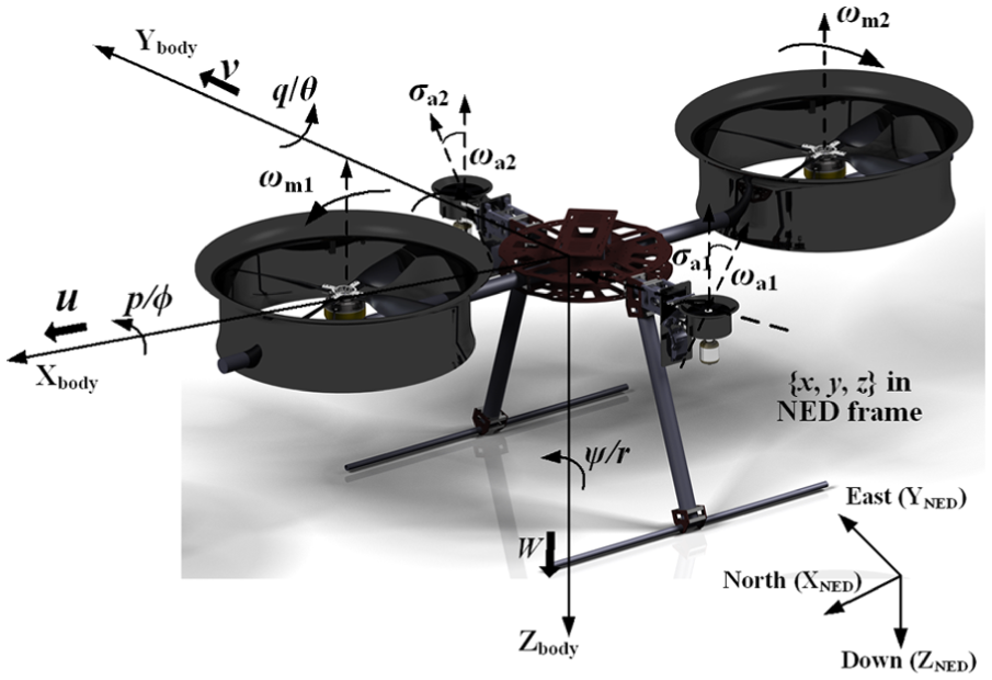
Illustration of system states and input components.
Physical description of the system inputs.

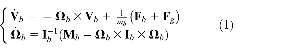
Rigid-body dynamics
Our UAV can be considered a rigid frame with two primary ducted fans and two auxiliary ducted fans; thus, the dynamics of the UAV can be modelled using the Newton–Euler equations
where


where the subscripts
The dynamic equations of the UAV are derived in the body-fixed frame. However, the state components must be derived in the earth-fixed frame for model trimming and linearization. The transformation between the two frames is derived using a standard yaw–pitch–roll Euler angle rotation. Based on the rotation, the velocities and attitudes related to the corresponding frame are calculated using the following equations

where

where c, s and t represent trigonometric sin, cos and tan, respectively.
Primary ducted-fan dynamics
Relative to a traditional open-air rotor, the novel ducted structure of our UAV has two new effects: (1) the duct can provide additional thrust due to increased air suction over the lip and (2) the duct produces a flow-turning effect due to the momentum change in the passing free-steam air. Johnson and Turbe 11 developed an inflow model to analyse these two features. The velocity and force vectors of the inflow model are illustrated in Figure 5.

Illustration of the inflow model.
The upstream velocity of the rotor can be calculated using the following equations

where U, V and W are the components of the body velocity vector; p, q and r are the components of the body angular velocity vector and
On the disk of the rotor, the angle of the inflow velocity vector is twisted due to the effect of the duct; therefore, the components of the turning inflow velocity can be described by

where
To streamline the derivation process, the inflow turning velocity vector is transformed to a body-fixed coordinate system as follows

where

where
In a previous study, 12 the thrust of the rotor was presented as a complex implicit integration, making model trimming and linearization challenging. Therefore, in this research, the primary ducted-rotor thrust is derived as an explicit expression based on the conservation theory of momentum and energy

where
Equation (10) describes the relationship between the thrust and induced velocity of the primary ducted fan. The simultaneous equations can be solved using general numerical computation methods. In this research, the bisection algorithm is used to solve the problem. Then, the thrust caused by the turning inflow can be calculated as

From the above calculations, the forces and moments generated by the primary ducted-fan rotors along each direction can be calculated as follows

Note that equation (12) describes the forces and moments of a single primary ducted-fan rotor. Since the rotation directions and locations (in body-fixed coordinates) of the two primary ducts are opposite, certain signs in the equations for the other primary ducted-fan rotor must be switched.
In our case, the control moments in the longitudinal direction are generated by a speed difference between the two primary ducted fans; therefore, the gyroscopic moments cannot be ignored. These moments can be calculated by

where
Moreover, the pitching moment of the ducted fan is a strongly nonlinear aerodynamic element. Therefore, accurate pitching moment modelling is a challenging aspect of a ducted-fan system. In Tobias and Horn, 13 the author assumed that the thrust generated by the duct is offset from the duct centreline, which is caused by velocity differences between the leading and aft portions of the duct. In Ohanian et al., 14 a wind tunnel for wind-on testing was developed, and the pitching moment was experimentally observed to be a function of thrust and airspeed. In the present research, a computational fluid dynamics (CFD) simulation technique is used to develop the approximate pitching moment model.
Auxiliary ducted-fan dynamics
The two auxiliary ducted fans in the proposed UAV have two primary characteristics: (1) they are primarily responsible for control forces and generating moments and (2) their dimensions are extremely small relative to the primary ducted fans. These features make it reasonable to simplify the auxiliary ducted-fan model as follows: (1) the forces of the auxiliary ducted fans can be modelled as vectors, (2) the corresponding factors can be obtained from the static-thrust estimation equation and (3) the moments caused by the air inflow can be neglected. Then, the components of the control forces and moments can be calculated as follows

where
Resistant drag model
The resistant drag on the proposed UAV includes two components: (1) fuselage drag and (2) forces on the body of the primary duct. The complete resistant drag model is given as follows

where
Actuator model
The properties of the system actuators significantly affect system performance. 15 Our previous report proposed an accurate actuator model based on the system identification technique. 16 In this case, the actuators include two types of parts: (1) two brushless direct-current motors (BLCDMs) and (2) two servos. The dynamic model of BLCDMs and servos can be described as follows

where
Structured attitude controller design
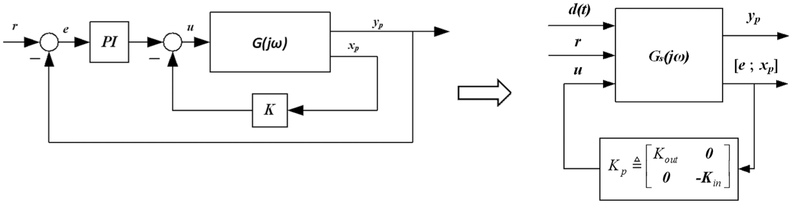
This section presents a robust feedback controller for the proposed novel UAV. The controller is designed based on the linearized model trimmed at the hovering point. The primary control objective is to track the attitude reference signal with approximately zero steady-state errors. The control system structure is shown in Figure 6. The control system includes two feedback loops: (1) the inner loop is a static output feedback controller responsible for stability augmentation and state decoupling and (2) the outer loop consists of a series of proportional–integral (PI) controllers applied primarily to ensure the desired attitude-tracking performance. This research is aimed at attitude control performance; therefore, the proposed outer-loop controller is employed for attitude tracking instead of location or speed tracking.

Control system structure.
Before executing the controller design, we present control targets for the closed-loop system: (1) the system should be settled with minimum overshoot and minimum state coupling, (2) the outer-loop responses should be settled within approximately 2 s to ensure satisfactory performance in practice and (3) the gain of the inner-loop controller should remain between 10 and 30 rad/s to ensure sufficient system sensitivity.
System description and model linearization
In section ‘Dynamic modelling’, nonlinear differential equations were derived as the comprehensive dynamic model of the proposed UAV. Then, the nonlinear model can be linearized at particular trimming points using multiple possible mathematical methods. In our case, the hovering condition is given particular attention, and a numerical perturbation method is applied for model trimming. The linearized model at the hovering condition can be described using the following state-space expression

where


Note that the aim of the control system is to track attitude changes; thus, the elements corresponding to the velocity states can be neglected in the system matrices. The nominal open-loop plant can be written as follows

where

Robust conditions for static output feedback control system
For the system shown in equation (20), the minimum state-space realization of the compensated plant can be described as

where the system matrices
where
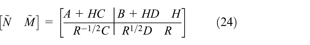
where
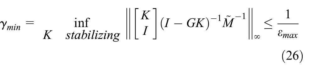
Then, in the normalized co-prime factorization framework with a feedback controller K, the robust condition of the system is given by
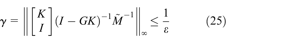
where
Controller reconstruction via frequency-domain tuning method
For conventional flight controller design, the stable-loop and tracking-loop controller are designed independently (as described elsewhere18,19), which may lead to decreased robustness and performance. In addition, the traditional controller parameter tuning is degraded to a linear matrix inequality (LMI) problem (as described elsewhere20,21), which may increase the conservative nature of the controller. In this research, the norm optimization problem is solved directly, and the proposed inner-loop controller and outer-loop controller are tuned simultaneously.
First, a definition of the output tracking error is given

where
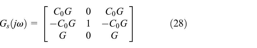
The nominal control architecture shown in Figure 7(a) can be reformed as the standard structure shown in Figure 7(b).
Control structure reformation.
In the proposed standard form, the fixed parameters and tunable elements are isolated in the augmented plant

where
Based on the robust H-infinity synthesis, 22 matrix H-infinity norms provide a measure of the size of output signals for certain classes of input signals. Therefore, the design requirements can be represented as normalized H-infinity constraints, which are shown in equation (30)

where

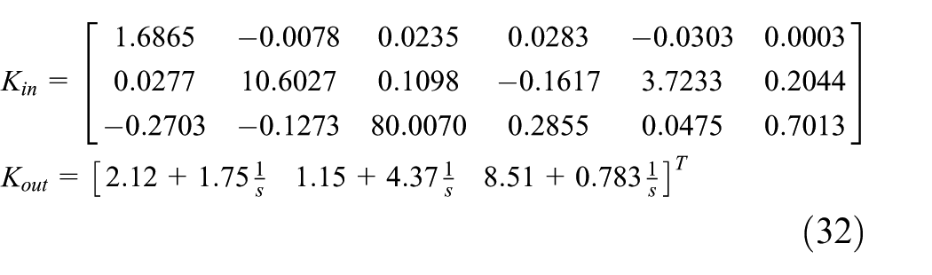
where the first two weighted norms in equation (31) are employed to measure tracking performance and the last weighted norm in equation (31) is employed to measure disturbance-resistant performance. However, since traditional H-infinity synthesis requires all designed constraints to be expressed in terms of a single closed-loop transfer function (as detailed elsewhere 22 ), we cannot use conventional methods to solve the proposed optimization. Therefore, a non-smooth H-infinity optimizer (as proposed and detailed elsewhere 23 ) is used to tune the controller elements simultaneously. The iteration results of the controller parameters are given in equation (32)
Computer simulation analysis
Based on sections ‘Robust conditions for static output feedback control system’ and ‘Controller reconstruction via frequency-domain tuning method’, the simulation model can be established using MATLAB®/Simulink®. Before simulating, a wind model is introduced as described elsewhere. 24 The wind disturbance signal is simulated at a velocity less than 5 m/s. The structure of the simulated closed-loop system is shown in Figure 8.

Simulation model of the control system.
Figure 9 shows the eigenvalue distribution map of the closed-loop system. The system achieves stability using the proposed feedback controller. Figure 10 shows the singular value of the closed-loop plant with wind disturbances. The plots indicate that closed-loop system offers robust stability and performance.
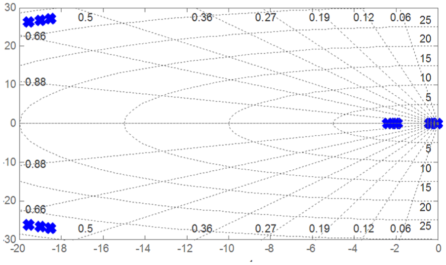
Eigenvalues of the closed-loop system.
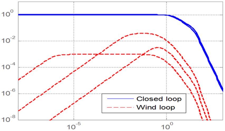
Singular values of the closed-loop system.
A series of computer simulations are used to evaluate the performance of the proposed attitude controllers. Figure 11 shows the responses to step-reference signals. The nonlinear model proposed in section ‘Dynamic modelling’ is applied in this simulation. The simulation results show that all closed-loop responses settle within 2 s with nearly no overshoots or static errors. The response fluctuations subject to wind disturbances are less than 5% of their static value, indicating reasonable resistance to external disturbances. Moreover, the state-decoupling performance is also clearly demonstrated.

Attitude component responses subject to step references.
Flight experiments
Experimental configuration
Structural parameters of the proposed UAV are shown in Table 3. The plant inertia matrix is derived from a three-dimensional model established using CATIA®/V5R20. The hardware of the experimental platform is shown in Figure 12. Brief descriptions of each component used in the experiment are presented in the next part of this section.
Structural parameters of the experimental plant.

C.G.: centre of gravity.
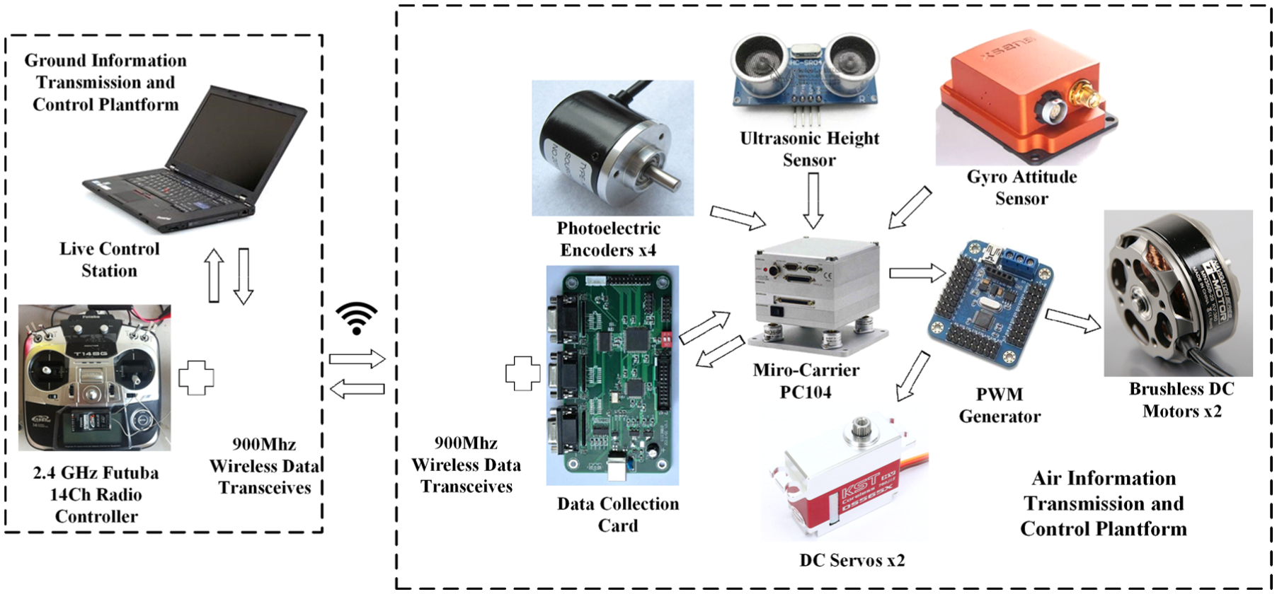
Control system hardware structure.
Ground control platform
The ground control platform includes a real-time ground station and a data exchange unit. The real-time ground station is a personal computer used for real-time monitoring and parameter adjustment. The data exchange unit consists of a 2.4 GHz Futaba 14-channel radio transmitter and a 900 MHz wireless data transceiver. The data exchange unit is used to exchange control signals between the ground station and airborne controller.
Air control platform
The air control system includes three parts: (1) the control unit, (2) the driving unit and (3) the measurement unit. The control unit is a micro-carrier PC (PC104) with a Linux operating system. The PC104 is connected to a pulse width modulation (PWM) generator via RS-232 serial ports. All the variant control commands are sent from the PC104 to the PWM generator primarily for control command decoding and PWM wave generation. The driving unit consists of two BLCDMs (Tiger-Motor/MN3508) and two direct current (DC) servos (KST/BLS 825). The measurement unit includes four photoelectric encoders, an ultrasonic height sensor, a gyro attitude sensor (with a sampling rate of 50 Hz) and a data collection card. The variable rotor speed (both the primary and auxiliary rotors) and attitude state information are measured and collected by the measurement unit. In addition, another information exchange unit is applied for data communication between the air and ground control systems through wireless radio signals.
Experimental results
Figure 13 includes pictures from the flight experiment. Certain layouts and applications of the experimental equipment are motivated by previous work.25–27 Before beginning the experiment, protection devices (shown in the figure) are employed to ensure the safety of the device and test personnel. During each experiment, constant power is supplied at 23 V. Signals are sent to the ground station, and all data are collected using the measurement unit. The results are then derived based on the collected data.

Flight experiment site.
Attitude response test
The controller proposed in this study is designed primarily via model-based robust feedback control theory. Therefore, the performance of the system model derived in section ‘Dynamic modelling’ is critical for controller design. To evaluate the reliability of the comprehensive system model and the corresponding controller, a channel response test is applied. In this experiment, each of the three attitude channels is tested independently (when one of the three channels is tested, the other two DOFs are restricted to protect the device). A step signal

Comparison of the simulation responses and experimental results for each channel.
Since the yaw angle is influenced by the initial azimuth angle, this error is artificially corrected before data processing and evaluation. The responses demonstrate that each of the three channels settles within 2.5 s, which is acceptable according to the design targets. Moreover, the steady-state error of each channel is within approximately ±0.5°, and the overshoots are reasonably small. The experimental results indicate that the system model in section ‘Dynamic modelling’ is reliable, and that the feedback controller performs well.
Free-hovering test
Since attitude control is the baseline target, a free-hovering experiment is performed to test the attitude control performance of the proposed system. In this test, the proposed UAV hovers 1.5 m above the ground, and the controller parameters are finely tuned based on the conclusions of section ‘Controller reconstruction via frequency-domain tuning method’ to improve the practical performance. In addition, the reference input angles are set to zero for each attitude channel. The attitude angle responses are shown in Figure 15.

Free-flight hovering test results.
According to the results, the steady-state error of the three channels is within ±0.5° with only small overshoots, indicating sufficiently stable attitude control performance of the proposed structured controller.
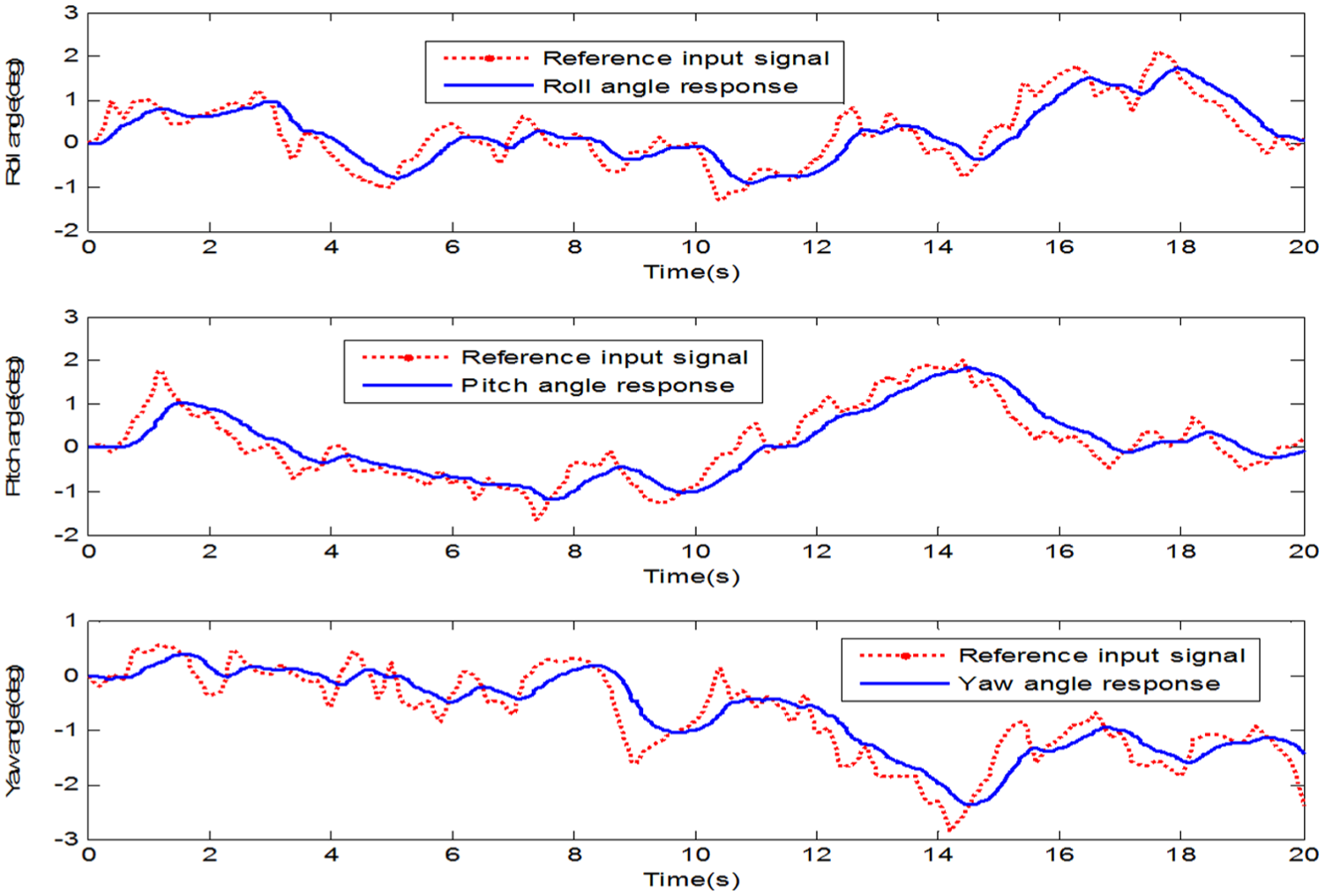
Attitude-tracking test
Another target of the proposed controller design is to achieve suitable attitude-tracking performance. Thus, an attitude-tracking test is used to evaluate the attitude-tracking ability of the closed-loop system. Two types of signals are used as reference inputs in this experiment. During the sine-tracking test, a sinusoidal signal

Sinusoidal tracking test results.
Random-tracking test results.
Conclusion
We present a novel ducted-fan UAV for practical performance improvement. The unconventional structure and state coupling make an effective attitude flight controller challenging for practical applications. A low-order structured feedback controller is provided to overcome the proposed challenges. In this study, a comprehensive mathematical model with reasonable accuracy and efficiency is established before executing the proposed controller design. An attitude response experiment is performed to test the reliability of this comprehensive model. Then, a structured multi-loop feedback controller is designed based on H-infinity synthesis as an attitude controller to provide cross-attitude decoupling and reference signal tracking. The controller parameters are solved and tuned using frequency-domain tuning tools with an NSO method. Then, a series of computer simulations and basic practical experiments are designed and performed to evaluate the stability and state-decoupling ability of the designed controllers. The collected data show that the proposed attitude controller achieves satisfactory stability, traceability and attitude state cross-decoupling. The proposed design targets are achieved. This research provides a strong foundation for future location-loop or speed-loop tracking based on the proposed novel UAV and provides valuable practical experiences. Since the performance of model-based controllers is highly dependent on the system model accuracy, we anticipate applying more advanced techniques such as system identification and other static tests to create a more accurate and instructive plant model. Moreover, other advanced control structures, such as adaptive controllers, will be studied to overcome severe uncertainties/disturbances or actuator/sensor faults. Finally, various field experiments will be designed to evaluate the control performance in more detail.
Footnotes
Handling Editor: Xiang Yu
Declaration of conflicting interests
The author(s) declared no potential conflicts of interest with respect to the research, authorship and/or publication of this article.
Funding
The author(s) disclosed receipt of the following financial support for the research, authorship and/or publication of this article: This research was supported by the Natural Science Foundation of China (NSFC) under grant no. 51505031.