
Abstract
To enhance the absolute position accuracy and solve complex modeling and computational complexity problems in traditional compensation methods for aviation drilling robots, a compensation method based on the extreme learning machine model was proposed in this article. The proposed method, in which the influence of geometric factors and the non-geometric factors of the robot is considered, builds a positional error prediction model based on extreme learning machine. As the input and output training data, the theoretical position and positional errors measured by a high-precision laser tracker were used to train and construct the extreme learning machine model. After the extreme learning machine model was constructed, the positional errors of prediction points could be predicted using the trained extreme learning machine. Then, the drilling robot controller could be directed to compensate for the predicted positional errors. To verify the correctness and effectiveness of the method, a series of experiments were performed with an aviation drilling robot. The experimental results showed that choosing an appropriate number of training points and hidden neurons for extreme learning machine could increase the computational efficiency without decreasing the high absolute position accuracy. The results also show that the average and maximum absolute position accuracy of robot tool center point were improved by 75.89% and 80.93%, respectively.
Keywords
Introduction
Aircraft assembly is one of the most important aspects of aircraft production and accounts for approximately half of the total aircraft manufacturing workload. The quality of aircraft assembly directly affects the life of the aircraft structure. The connection between the parts in aircraft assembly is based on riveting and bolting. Drilling is an important process before riveting and bolting, and the current form of drilling is primarily manual; however, the drilling hole quality and connection quality do not meet the quality requirements of high-performance aircraft.1–3 The application of aviation drilling robots can greatly improve the quality of the hole and the quality of the connection. 4 In addition, these robots can improve the passing rate of the product. Repeatability and absolute accuracy, important indices of aviation drilling robots’ positioning accuracy, are the basis of all processes. The aviation drilling robot consists mainly of the end effector and the robotic manipulator. The end effector is attached to the flange of the robotic manipulator. Thus, positional accuracy is determined primarily by the robotic manipulator. Current robotic manipulators generally achieve high repeatability. For example, the repeatability of a KUKA KR210 can reach ±0.06 mm, whereas the absolute accuracy is only ±3 mm. The absolute accuracy cannot meet the accuracy requirement of ±0.5 mm in aircraft assembly.5,6 An increasing number of aviation drilling robots are operated by offline programming.2,7 Generally, drilling robots with only high repeatability are not adequate for high-end manufacturing, which also requires high absolute accuracy. 8 Thus, high absolute accuracy has been pursued by researchers internationally.9–20
Sources leading to a loss of absolute accuracy are usually concurrent. Errors caused by link length, non-parallel axes, base misalignment, manufacturing errors, and assembly errors are classified as geometric errors and account for approximately 90% of all errors. The other 10% of errors are caused by the payload, thermal deflection, gear backlash, servo error, and so on, and they are called non-geometric errors.12,13 Therefore, studies have considered geometric errors for calibration, while non-geometric errors have been ignored.14,15
Two types of compensation methods have been developed: model-based compensation and model-free compensation. 16 In the model-based compensation method, errors of kinematic parameters are identified based on the kinematic model, which is constructed first. A Denavit–Hartenberg (DH) model is a convenient method for determining the deviation of kinematic parameters.17,18 When adjacent axes are parallel, the solution will be singular. To solve this problem, a modified Denavit–Hartenberg (MDH) model is proposed. Compared with a DH model, a MDH model adds an additional parameter representing the rotation around the y axis.15,19 An S-model that has six parameters can also overcome the singularity problem of the DH model.20–22 A parameter identification method based on the S-model is proposed. 22 The product-of-exponential (POE) model can be used to construct the kinematic model of a robot. 23 He et al. 24 proposed a parameter identification method for robot calibration based on POE. In model-based compensation, in addition to modeling, parameter identification is another difficulty. The linear least squares method, 25 non-linear optimization procedure,26,27 iterative linearization, 28 extended Kalman filter,15,27–29 and Levenberg–Marquardt 30 are all algorithms for parameter identification. The model-based methods generally ignore small errors when modeling, which results in non-ideal compensation accuracy. The model-based methods are not universal for all types of robots and have the problems associated with complex modeling and computational complexity.
Another type of compensation method, the model-free method, holds that position errors and robot joint values or robot positions are correlated. A number of approaches, such as Fourier polynomial,31,32 inverse distance weighting, 33 kriging, 16 and artificial neural network (ANN),15,34,35 have been utilized to predict position errors. However, Fourier polynomial is limited because of its low accuracy and high complexity. Inverse distance weighting is only applicable when the movement of the robot space is in a small range. The kriging method is complex, and it is challenging for field engineers to master.
Compared with the methods mentioned above, the ANN method, which has high learning ability and high adaptability, can constantly adjust the weight of the associated node so that the output can approach the desired results. Therefore, the ANN method has been rapidly developed to provide higher precision for industrial robots. Single-hidden-layer forward neural network (SLFN) is a traditional ANN that has been widely used. 36 However, the SLFN method is limited by slow training, the difficulty of obtaining a global optimal solution, and the difficulty of choosing a learning rate. To solve these problems, the extreme learning machine (ELM) algorithm has been proposed by Huang et al.37,38 Compared with the ordinary SLFN, the ELM algorithm, which presents improved generalization, simplifies the training without iteration. In addition, ELM can be used to compensate the unknown nonlinearity for industrial robot, which is a non-linear system, and has the advantage of high efficiency. 39
A novel compensation method based on ELM was proposed to improve the absolute position accuracy and solve the problem of complex modeling and computational complexity. The method does not need to construct a kinematics model of the robot and identify the kinematic parameters. Considering the influence of the geometric factors and the non-geometric factors of the aviation drilling robot, the proposed method built a positional error prediction model based on ELM. As the input and output training data, the theoretical position and positional errors measured by a high-precision laser tracker were used to train and construct the ELM model. After the ELM model was constructed, the positional errors of prediction points could be predicted using the trained ELM. Then, the drilling robot controller could compensate for the predicted positional errors.
The rest of the article is organized as follows: section “Compensation principle” describes the compensation principle based on ELM; section “Experimental results and analysis” presents the experiments and analysis of the results for the aviation drilling robot; and section “Conclusion” discusses the conclusions.
Compensation principle
ELM principle
The drilling robot tool center point (TCP) is used as the research object to study compensation in this article.Figure 1 shows the structure of a three-layer ELM. The theoretical position Pt(xt yt zt) of the robot TCP is the input of the ELM, which consists of three nodes. The three nodes in the input layer represent the three elements of the theoretical position vector


Structure of ELM.
Given N different learning sample pairs

where


In addition, Gi (

where g is the activating function of the hidden neurons.
The ELM searches for the optimal pairs

The matrix form of equation (2) can be written as follows

where
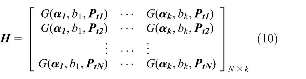


ELM specifies the number of the hidden neurons (i.e. k) and assigns the learning parameter pairs of the hidden neurons (i.e.

where

After the matrix
The illustration of the ELM training process is shown in Figure 2. The theoretical position

where

ELM training.
Positional error compensation
The compensation process of positional errors for a drilling robot is described in Figure 3. After the ELM is trained, the theoretical position

where
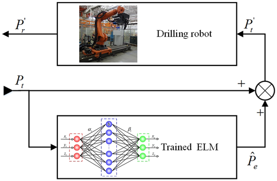
Compensation of the positional error.
To reach the specified location, the controller would give the drilling robot the position coordinates
Experimental results and analysis
As shown in Figure 4, the practical compensation of an aviation drilling robot is used to verify the compensation method in this article. The experimental setup consists of a KUKA KR210 R2700 robotic manipulator, an end effector, a laser tracker, and an accompanying spherically mounted reflector (SMR). The end effector is attached to the flange of the robotic manipulator. The spherical center of the SMR attached to the end effector is on the spindle axis of the end effector, as shown in Figure 4. The spherical center of the SMR is regarded as the drilling robot TCP. The KUKA KR210 R2700 robotic manipulator and drilling end effector are the key parts of the aviation drilling robot. The robotic manipulator is a 6-degree-of-freedom (DOF) serial manipulator. The repetitive positioning accuracy of the robotic manipulator is ±0.06 mm, and its absolute positioning accuracy is not mentioned in the specification. The type of the laser tracker is a Leica AT901, and its absolute distance measuring accuracy is 7.5 + 3 μm/m.

Setup of an experimental compensation system.
Measuring TCP
The drilling robot TCP is used as the research object to study compensation in this article. The difference between the real computer-aided design (CAD) model and the ideal CAD model of the end effector leads to misalignment between the real TCP and theoretical TCP. Thus, the drilling robot TCP must be measured before compensation to obtain the position relation between the TCP and flange frame of the robot. A XYZ-4-points method is used to determine the TCP in this article. The principle of the XYZ-4-points method is that the robot TCP moves to the same point from four difference postures. The position parameters of the flange in four difference postures are calculated by the robot control system to obtain the robot TCP. The SMR cannot be close to a real reference point to measure the TCP in practice as shown in Figure 4; therefore, a virtual XYZ-4-points method in coordination with a laser tracker is used. A robot controlled by the control system moves so that the SMR is close to a virtual point from four different postures. When the positional error between the SMR and the virtual point is less than 0.02 mm (absolute distance measuring accuracy of the laser tracker in practice), the SMR is considered to coincide with the virtual point. Then, the robot TCP can be obtained by the robot control system.
Establishing the robot base frame
To obtain the absolute positioning accuracy, the robot’s base frame must be established first. The positional errors of the robot TCP reflect the robot absolute positioning accuracy. Thus, the positional errors of robot TCP are measured in the robot base frame. In this article, spatial analyzer (SA) software developed by New River Kinematics, in coordination with a laser tracker, is used to establish the robot base frame and measure the position of the robot TCP in the robot base frame. Robotmaster software is applied to generate an offline program of the robot.
The robot base frame is established as follows:
L-type path, which consists of two lines, is designed to generate corresponding offline programming in Robotmaster, as shown in Figure 5. One of the two lines parallels the YB axis of the robot base frame, and another parallels the ZB axis.
A set of TCP positions measured while moving along the YB axis positive direction is used to fit the YA axis, as shown in Figure 5.
When the TCP moves to the point OA, the theoretical coordinate value of point OA is recorded and measured with the SA software.
A set of TCP positions measured while moving along the ZB axis negative direction is used to fit the ZA axis.
Let us construct the {A} frame with its origin at the point OA in which two fitted lines are the YA axis and ZA axis, respectively, in SA software.
The {A} frame is constructed approximately parallel to the robot base frame. The {A} frame is translated in terms of the value recorded in equation (2), and the robot base frame is established.
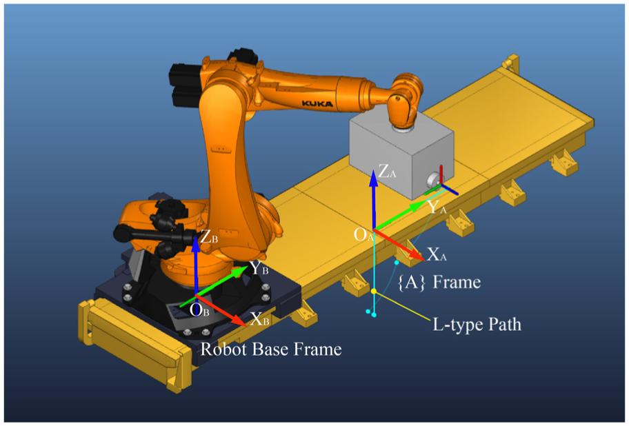
Establishing the robot base frame.
Because of the measurement errors of the laser tracker, the line fitting errors and principle errors, the constructed robot base frame cannot absolutely coincide with the theoretical robot base frame. Therefore, a deviation is observed between the positional errors of the robot TCP measured in the constructed robot base frame and the theoretical positional errors. The deviation is the constructed error of the robot base frame. In practice, the target points are applied in the constructed robot base frame, and the compensation of the robot TCP is also applied in the constructed robot base frame; thus, the constructed errors of the robot base frame have little effect on robot compensation.
Influencing factors of absolute position accuracy
The number of training samples and the number of nodes in the hidden layer are the important factors that influence the training effect of the neural network. Thus, the training effect of the ELM algorithm, one of the traditional neural networks, is influenced by the number of training points and the number of nodes in the hidden layer. To obtain the optimal parameters, a set of experiments are implemented.
Effect of the number of training points on absolute position accuracy
The training effect of the ELM is influenced by the number of training points. Thus, the training effect of the ELM has an impact on the absolute position accuracy of the robot. To obtain the relationship between the absolute position accuracy and the number of training points for the ELM, an experiment is performed on the aviation drilling robot.
According to the method mentioned above, the robot TCP is measured, and the robot base frame is established first. Subsequently, 2000 random points in the robot workspace are chosen, and they are evenly distributed in the robot workspace. The path of the robot TCP is designed in the Robotmaster software, and the corresponding offline program of the robot is generated. After the robot TCP moves to the samples, the real position of robot TCP can be measured using the laser tracker. Then, the real positional error of the 2000 points can be calculated. In addition, 100 random points, 200 random points, …, 2000 random points from the 2000 measurement points mentioned above are chosen to train the ELM. The hidden layer is composed of 40 neurons. A sum function is used as the activating function of the ELM. After 20 ELM models are constructed, 150 random points are used to obtain absolute position accuracy using 20 ELM models. The experimental results are shown in Figures 6 and 7.

Effect of the number of training points on the maximum positional error.

Effect of the number of training points on the average positional error.
The maximum positional error and average positional error are two important indexes of absolute position accuracy. The experimental results show that when the number of training points is less than 300, the maximum positional error and average positional error reduce as the number of training points increase. When the number of training points is greater than 300, as the number of training points increase, the maximum positional error and average position error tend to be stable.
In real applications, more points for ELM training take more measurement time, training time, and workload. Choosing the appropriate number of training points for the ELM can ensure high absolute position accuracy and reduce the time and the amount of work.
Effect of the number of the nodes in the hidden layer on absolute position accuracy
The number of the nodes in the hidden layer is another important factor influencing the training effect of the ELM. In addition, 1000 random points from the 2000 measurement points above are selected for ELM training, and the numbers of nodes in the hidden layer are 5, 10, …, 100. After 20 ELM models are constructed, 150 random points are used to obtain the absolute position accuracy using 20 ELM models. The experimental results are shown in Figures 8 and 9.

Effect of the number of the nodes in the hidden layer on the maximum position error.

Effect of the number of the nodes in the hidden layer on the average position error.
From Figures 8 and 9, if the number of nodes in the hidden layer is less than 20, the maximum positional error and average positional error all have a negative correlation with the number of nodes. If the number of nodes is greater than 20, the maximum positional error and average positional error are nearly equivalent to a constant.
The calculations and computation time will increase as the number of nodes in the hidden layer increases. The experimental results show that choosing the appropriate number of nodes in the hidden layer for the ELM can increase the computational efficiency without decreasing the high absolute position accuracy.
Positional error compensation
To verify the effectiveness of the compensation method in this article, experiments were conducted on an aviation drilling robot. In practice, the position accuracy of holes is basically determined by the maximum positional error rather than the average positional error. Hence, when the average positional errors with difference parameters are nearly consistent, the minimum maximum positional error is optimal. Figures 6 and 7 show that when the number of training points is greater than 300, the average position error tends to be stable. When the number of training points is 1000, the maximum positional error is minimum. Similarly, Figures 8 and 9 show that when the number of nodes is 40, the maximum positional error is minimum.
Thus, the data of 1000 random points from the 2000 points mentioned above are chosen to train the ELM. The hidden layer is composed of 40 neurons. A sum function is used as the activating function of the ELM.
After an ELM is constructed, 150 random points in the robot workspace are chosen to verify the compensation method. The positional errors of 150 random points are measured before and after compensation. The experimental results of positional errors of 150 measurement points before and after compensation are shown in Figures 10–12. The histograms of positional errors along the X, Y, and Z axes before and after compensation are described in Figures 13–15. The detailed statistical results of the positional errors are shown in Table 1. According to the experimental results, the positional errors on the X, Y and Z axes after compensation in the error range and average errors are less than the positional errors before compensation. The experimental results show that the proposed compensation method can enhance the position accuracy of aviation drilling robot in aircraft assembly.

Positional errors on the X axis of robot TCP.

Positional errors on the Y axis of robot TCP.

Positional errors on the Z axis of robot TCP.

Histogram of positional errors along the X axis.

Histogram of positional errors along the Y axis.

Histogram of positional errors along the Z axis.
Experimental results of the positional errors.

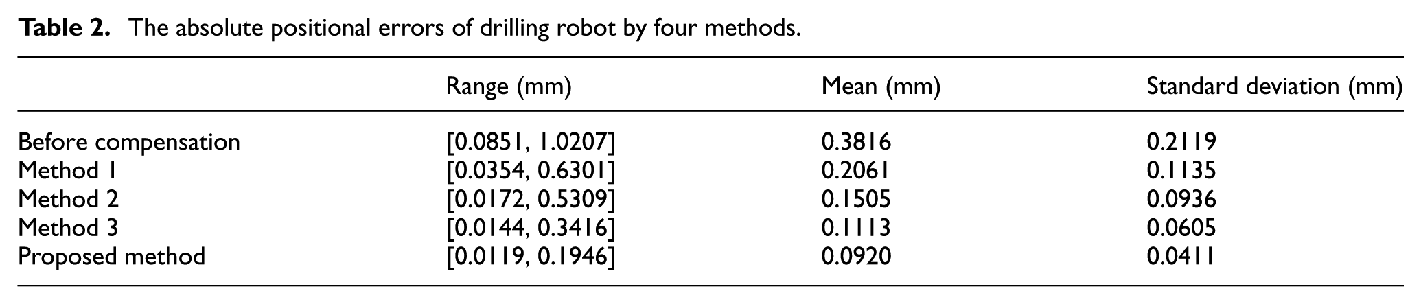
To verify the high accuracy and high efficiency of the proposed method, three methods, which are referred to as method 1, 33 method 2, 16 and method 3, 15 are compared with the proposed method. Method 1 and method 2 were all model-free methods and they used the error similarity to estimate the positional errors of sampled points. Method 3, a traditional model-based method, developed the kinematic model of robot and identified the parameters of kinematic model. Figures 16 and 17 and Table 2 summarize the compensation results of four methods. The results show that the proposed method achieves higher position accuracy than the rest methods. The validation results also show that the average absolute positional errors before and after compensation are 0.3816 and 0.0920 mm, respectively. The maximum values before and after compensation are 1.0207 and 0.1946 mm, respectively. The average and maximum absolute position accuracies of the robot TCP are improved by 75.89% and 80.93%, respectively. From the experimental results, the compensation method in this article can meet the position accuracy requirement of an aviation drilling robot in aircraft assembly.

The absolute positional errors of drilling robot after compensation for four methods.

Histogram of absolute positional errors after compensation for four methods.
The absolute positional errors of drilling robot by four methods.
The four methods are programmed in MATLAB running on a Windows computer with a 2.6-GHz Intel Core i7-6700HQ CPU and 8 GB RAM. Table 3 shows the running time for training or parameter identification to estimate the positional errors of 150 sample points based on the three methods. Table 3 shows that method 3 requires more time than the other methods. The running times of method 1 and method 2 are almost 6 times and 54 times that of the proposed method, respectively. The results demonstrate that the proposed method has the advantages of low computational complexity and high efficiency.
The results of running time.

Conclusion
A compensation method based on the ELM model for an aviation drilling robot was proposed to enhance the absolute position accuracy and solve the problem of complex modeling and computational complexity in the traditional compensation method.
The influence of the geometric factors and the non-geometric factors of the aviation drilling robot is considered in the compensation method based on the ELM model. The theoretical position and positional errors measured by a high-precision laser tracker were the input training data and output training data used to train and construct the ELM model. The ELM could predict the positional errors of the prediction points. The drilling robot controller compensated for the predicted positional errors.
To verify the effectiveness of the proposed compensation method in real applications, experimental compensation was conducted on an aviation drilling robot. After error compensation, the average absolute positional errors were improved from 0.3816 to 0.0920 mm, and the maximum values improved from 1.0207 to 0.1946 mm. The experimental results showed that the compensation method in this article can improve the absolute position accuracy for an aviation drilling robot, has the advantages of low computational complexity and high efficiency, and meets the requirements of aircraft assembly.
The number of training points and the nodes in the hidden layer for the ELM were two important factors influencing the absolute position accuracy of a drilling robot. To obtain the relationship between the absolute position accuracy and the two factors, a series of experiments were conducted on an aviation drilling robot. The experimental results demonstrated that choosing the appropriate number of training points and hidden neurons for the ELM can ensure high absolute position accuracy and reduce the time and amount of work.
Footnotes
Handling Editor: Chenguang Yang
Declaration of conflicting interests
The author(s) declared no potential conflicts of interest with respect to the research, authorship, and/or publication of this article.
Funding
The author(s) disclosed receipt of the following financial support for the research, authorship, and/or publication of this article: This research is partially supported by the National Natural Science Foundation of China (no. 61375085) and the Foundation of Shanghai Aircraft Manufacturing Co., Ltd (no. 32284001).