
Abstract
For its compact and flexible design, a novel miniature hydraulic actuation scheme is proposed for use in applications especially where both size and power are extremely important. The system works on a volume-controlled method using miniature cylinders. In order to describe the impact of hose deformation on the system, a lumped-parameter hose model is proposed, and coefficients in the model are determined on the basis of experiments with an existing prototype. A position tracking controller with a disturbance observer is designed for a miniature hose-connecting hydraulic actuation system. Tracking control for the target displacement is arranged as an external circuit of pressure compensation to eliminate the tracking error and an inner circuit of pressure compensation which operates by observed disturbances and oil pressure in the hose. Lyapunov theory is employed to verify the stability of the system with the disturbance observer. The disturbance observer–based controller has much better tracking performance than conventional proportional–integral–derivative controllers, which can substantially offset negative effects of the hose.
Keywords
Introduction
Background
Miniature hydraulic actuators have specific significance because of their compatibility, lightweight, and fast response. 1 Actuator size can be reduced to cater for installation and operation within extremely narrow spaces, which tends to be unachievable using traditional electric or mechanical actuation systems. Therefore, miniature hydraulic actuators are especially suitable for applications like wind tunnels, aero airborne actuators, and lightweight moving machines with demanding geometry, weight, and output power required.2,3
Valve control and pump control are traditionally two frequently used solutions to hydraulic proportional control systems. Generally, valve-controlled systems offer simply configuration and quick response, whereas pump-controlled systems have high efficiency and low response.4,5 Thus, valve-controlled systems are used more widely in applications with high requirements of accuracy and dynamics. Both valve-controlled systems and pump-controlled systems, however, need to equip a pressurized-oil supplier, which would no longer meet the requirement of the actuation system to be compact and portable. Avoiding a pressurized-oil supplier, directly driven hydraulic actuators are vastly superior in the demands mentioned above. 6 They can be powered by linear motors or motor-driven hydraulic cylinders using ball crew transmission. For miniature hydraulic actuation units, hose instead of pipe connects a valve to a cylinder or between two cylinders, which allows flexible actuation, as well as tight space installation and maintenance. 7 In addition, long-distance hose-connecting can isolate the object actuator from the power section of the system so as to avoid atrocious conditions via remote control.
Expansion of pressurized oil chamber enclosed by hose inevitably involves the no-response stage of the actuator during the initial actuation stage, which has nonlinear effects on full-range actuation. This problem becomes especially prominent in miniature long-distance hose-connecting actuators. Therefore, exploring an effective control method to eliminate the influence of pressurized volume variation is significant in improving the system robustness.
Literature review
Most researches dealing with the control of hydraulic actuation systems are aimed at eliminating nonlinear effects or improving tracking performance. Literature on this topic is vast and difficult to summarize in a single paper; however, the following examples will be used to illustrate the range of different control methods that have been implemented to improve such tracking performance.
A position control system combining a hydraulic actuator with a servo motor was designed to overcome the difficulty of theoretically uniform output force request and bias compensation. A proportional–derivative (PD) controller was used in the system and verified to have micrometer-level positioning ability. 8 Taking nonlinearities of friction and internal leakage into consideration, another method of position control strategy of an electrohydraulic actuation system was implemented by employing a fuzzy logic controller (FLC) whose parameters were optimized using particle swarm optimization (PSO). 9 A velocity feedback was added in a position control model to improve the bandwidth of a servo-hydraulic linear actuator. A fifth-order linear state space model of an actuator was derived and validated with experiments. Velocity feedback in simple proportional position control can achieve higher control bandwidth. 10 Continuing in efforts to make linear hydraulic actuators more robust across a wide range of operating conditions, researchers have implemented servo controller design for a hydraulic servo system with a load of large inertia, low stiffness, and multi-stage resonance. They combined notch filters and peak filters, a disturbance observer (DOB) in the feedback path and low-pass filter, PD compensation, and lead correction to complete resonance rejection. Similarly, a multiple inner-loop control strategy was adopted to improve pump backlash and nonlinear friction.11,12 A study shows that the robustness and stability of a DOB-based explicit force control system changes by environmental impedance variations and can be improved using an explicit environmental impedance estimation method. To suppress the interference between the position and force control systems and realize a bilateral control system, validity of the modal space disturbance observer (MDOB)-based decoupling method was verified on a multiple degree-of-freedom (DOF) system.13,14 DOB was also used to compensate parametric uncertainties and uncertain nonlinearities in an energy-saving electrohydraulic servo system. 15 Simple adaptive control (SAC) method is composed of a conventional proportional–integral–derivative (PID) feedback control system and a feedforward control system to enhance the tracking performance with a significant reduction in position tracking error. 16 A variable structure compensation term was added to the conventional PID control in asymmetrical hydraulic cylinder systems. 17 A fuzzy PID controller, which has advantage over traditional PID controllers, was utilized to reduce hydraulic pressure oscillation in hydraulic crane system. 18 A mathematical model of the servo drive hydraulic control was established, and an algorithm of controlling the nonlinear object was adapted using the linearization method of the model process to compensate disruptions like friction and changeable load powers mass. 19 For a single-ended cylinder in a pump displacement controlled circuit, circuit arrangement is necessary in order to balance unequal flow rates entering and leaving the cylinder volumes. Furthermore, compensations in the circuit including pressure oscillations and quotient group sliding were implemented and a Lyapunov stable control scheme was designed and verified to achieve expected stability of hydraulic nonlinearities and operator dynamics for a single-ended hydraulic actuator. 20 Few researches have been carried out to investigate hose nonlinear effects on hydraulic control system. A power bond graph was utilized to establish the flexible hose model to develop electrohydraulic proportional control system with the flexible hose. Effects of the hose parameters on dynamics characteristics of the hydraulic system were initially studied.21,22
Objectives
The following research questions have motivated this work: What is a feasible arrangement catering for compact, flexible, and portable operation needs? How does long and thin hose impact the position control in a miniature hydraulic actuation system? Can a simple feedback control approach be used to offset the hose effect by reducing the position variability in operator command-inputs, improving the tracking performance of a miniature linear hydraulic actuator? In this article, a novel miniature hydraulic actuation solution is proposed for use in applications where both size and power are extremely important. In the system, flexible hoses connect two cylinders and hose deformation has a great influence on displacement accuracy of the actuator. A lumped-parameter hose model is put forward to describe the hose characteristic and facilitate a more precise model for a miniature cylinder control cylinder actuation system. Some coefficients in this model are determined on the basis of experiments with an existing prototype. Using this model, simulation verification of the hose effect on the control system is carried out. Then, a position tracking controller with a DOB is designed for the miniature long-distance hydraulic actuation system. Lyapunov function is constructed to prove stability of the closed-loop system with DOB. In summary, this hose model is certified in the fact that it is necessary to describe long and thin hose in long-distance hydraulic actuation system and that using a position tracking controller with a DOB, the system exhibits better tracking performance than conventional PID controllers across most of the operation conditions.
Descriptions
Figure 1 shows a schematic of a novel miniature cylinder control cylinder system with a long and thin hose connection. Here, two cylinders are as follows: (1) the cylinder driven by the servo motor is called the power cylinder, (2) while the other one is called the actuation cylinder. The electric servo unit is composed of a servo motor, a retarder, and a screw ball. To make the actuation cylinder extend, the motor rotates based on pulse command from the controller. The screw ball transforms the rotation into linear motion and thereby causes the power cylinder to retract. Oil enclosed by two rodless chambers, and the hose between them is pressurized until the actuation cylinder extends, carrying the load mass. Conversely, the motor reverses, causing the actuation cylinder to retract. Transducers are arranged to collect the displacement Xpo, the rodless chamber pressure P1, and the rod chamber pressure P2 of the actuation cylinder as the feedback or the state parameters into the controller. A long and flexible hose connects chambers of these two cylinders to keep the measure and control section of the system far from severe actuation environment. The power section of the system can be separated from the actuator by simply disconnecting the hose and then can be reassembled to build a whole system, which allows the system more easily move to other actuation locations.

Schematic of hose-connecting miniature actuation system.
Modeling and analysis
Cylinder model
The power cylinder runs as the input of the control system while the actuation cylinder is the output. Since the external leakage coefficient Ce is as low as 4 × 10⁻¹⁷ m3/(s·Pa) and the oil pressure does not exceed 10 MPa, the leakage flow rate is no more than 0.4 mm3/s during short time actuation. Therefore, the leakage of the two cylinders in a single actuation process is negligible. Because neither relieving oil nor friction pair leakage exists in the system and the system does not work as high-frequency reciprocating motion, the problem of hot oil is inessential. An accumulator is connected to refill the hose and cylinder or charge itself while it is disconnected as soon as the refilling or charging is done, which is not the point of the paper though. In the light of the comparatively great hose deformation rate, volume variation rate of pressurized oil is negligible. And, the cylinder mass is also negligible. Force and flow rate analysis of the actuation cylinder extension give


where Ft is the uncertain load force and other external disturbances, Vh1 is the pressurized volume enclosed by the hose connecting two rodless chambers, Vh2 is the pressurized volume enclosed by the hose connecting two rod chambers (namely, hose volume below if no special statement), m is the load mass, and f is the friction of cylinders which includes static friction force and viscous friction force. Others are shown in Figure 1.
Hose model
In view of similarities between oil flowing in pipework with current through electric circuit, a lumped-parameter method is adopted.21,23Figure 2 depicts the mathematical relationship between pressure and flow rate at two ends of the hose. Similarly, pressure and flow rate in hose are taken, respectively, as voltage and current in the circuit of the model. R represents the flow resistance of the liquid in hose, L stands for the flow inertia, and C describes the characteristic of pressurized liquid and hose deformation.

Lumped-parameter hose model.
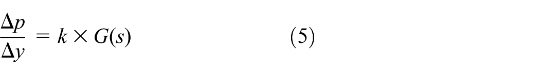
Compared to effects of hose elastic deformation on the flow rate in hoses, both fluid inertia and resistance are negligible. Based on the hose model in Figure 2, the transfer function of the outlet flow rate against the inlet pressure is

In general, hose exhibits much greater deformation than metal pipe. But under dynamic pressure, both static volume variations relating to steady oil pressure and dynamic volume variations caused by hose viscoelastic deformation should be considered. In this case, C is not a constant and involves a damping to describe dynamic deformation process of hoses. A lumped-parameter submodel for the viscoelastic effect of hoses is established to describe C as shown in Figure 3.

Submodel for viscoelastic effect of hoses.
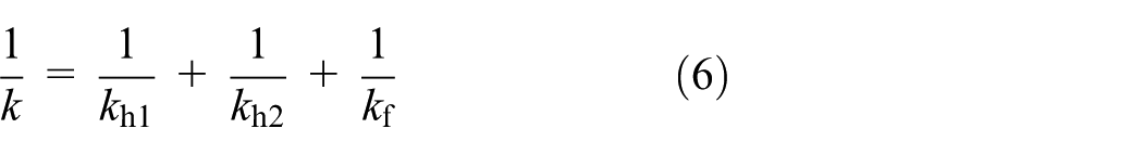
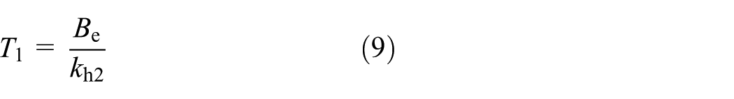
In Figure 3, p is the oil pressure in hose (MPa); y is the internal diameter variation of the hose; kf is the equivalent coefficient transforming compressed oil volume to elastic deformation of hose wall (N/m3); and kh1 and kh2 are the static and dynamic elastic coefficients of hose wall, respectively, (N/m3). Be is the damping coefficient.
According to the above model, the relationship between oil pressure p and internal diameter d can be written as
where


where r is the internal radius of the hose.
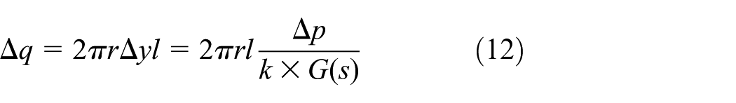
Assuming l is the hose length and Δp is variation of oil pressure, hose volume variation is given by

Neglecting the comparably small term of πΔy2, variation of oil pressure Δp is
The hose flow capacitor, C, is therefore

As it is difficult to determine k1, k2, and Be, experimental identification is a viable option.
Observer and controller
State space model
In order to simply construct an operator with a DOB, the described system model using state space approach is obtained. Combining equations (1) to (4) gives

State variables of the system is given by

Then, in combination with equation (14) and equation (15), a state space to describe system can be given as

This completes the mathematical model of the system.
DOB design
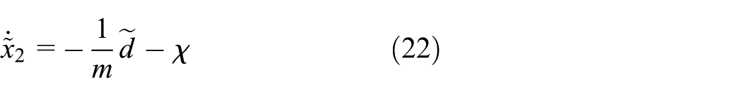
In order to utilize the backstepping method, the system falls into the strict feedback form. A new state variable

In order to observe the uncertain parameter, an extended state observer of x2 is given by

where


The adaption law is chosen as
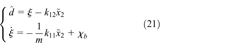
where k11 and k12 are the positive constants; χb is the extra corrector term designed to ensure the stability of the closed-loop system. It is also deduced further down. Derivative of
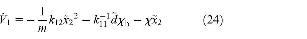
The Lyapunov function is defined by

Combining equation (23) with equations (21) and (22), time derivation of V1 gives
Position track controller
The controller includes an outer loop for position tracking and an inner loop for load pressure compensation. The controller is designed using a recursive backstepping procedure as follows. The position tracking error is defined as

A sliding surface s is given as

where λ is a positive constant. Using equation (17), the time derivative of s is written as

Then, a pressure compensation operator
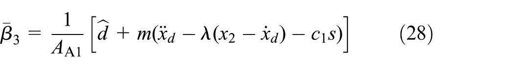
where c1 is a positive constant. The load pressure error is given by

Substituting equation (27) into equation (28), the time derivative of s is rewritten as

The Lyapunov function is defined by

where k2 is a positive constant.
Then, combining equation (24) with equation (28), the time derivative of V2 gives

Extra corrector terms χb and χ are chosen as

Substituting equation (32) into equation (33), now the time derivative of V2 gives

Then, an actual control law for u will be determined. The time derivative of

The control of u is designed as

where c2 and k3 are positive constants.
Combining equation (35) with equation (36) yields the derivative of

Now, the Lyapunov function is defined as

Combining equations (31) and (37) with equation (38), the time derivative of V gives

Thus, the DOB and the position track controller are used to ensure the stability of the closed-loop system.
Results and discussion
In order to obtain a correct hose model suitable for the system presented in this article, coefficients in the lumped-parameter hose model are determined by fitting the testing values of an existing prototype (shown in Figure 4). Two pressure transducers, two pressure gauges, and two linear displacement transducers are arranged to gather hose pressure and cylinder displacement needed. Figure 5 illustrates comparison between the simulation using the hose model and the prototype testing results with the best fitting curve. Here, the speed of the power cylinder of 0.003 m/s is preset, and the system runs for 10 s. Figure 5 shows that when the power cylinder moves up to 4.5 mm, pressure in the hose reaches 0.41 MPa, a minimum pressure to move the no-load actuation cylinder, which well matches the testing result of the prototype. The difference between the model and testing is smaller and stable after the actuation cylinder moves. Simulated hose pressure is lower than the tested before the power cylinder move to 3 mm. It can be interpreted that the bubble in the cylinders and hoses affect pressurizing which is not modeled in system. Accordingly, it can be concluded that the hose model used is accurate.
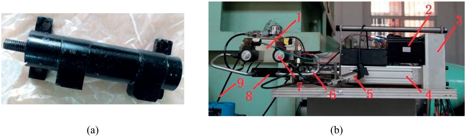
The existing prototype: (a) target cylinder and (b) electric servo unit and power cylinder.

Comparison of the hose model to prototype testing.
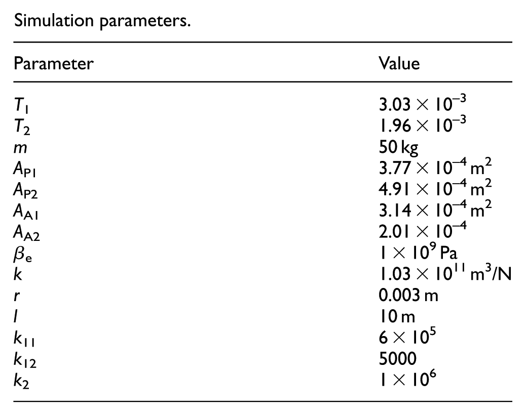
In order to simulate the effects of hose deformation on the control system and validity of the DOB, the mathematical model established above are solved using MATLAB/Simulink tool package. Some parameters required are set as listed in Appendix 2.
An open-loop arrangement is used to evaluate the effects on the system qualitatively, comparing simulation results of the system with and without hose model included. Simulation runs on open-loop arrangement for time length of 0.1 s, taking vP = 0.5 m/s and Ft = 500 N. Figures 6 and 7 show the displacement and pressure in the rodless chamber of the actuation cylinder, respectively. Figure 6 implies that hoses do induce a wider no-response stage of the actuation cylinder during the system start. No response of displacement lasts for about 0.03 s. In Figure 7, it is obvious that the hoses discourage pressurization of the actuation chamber. The displacement output and the actuation pressure tend to stabilize faster because hoses increase the system damping.

Open-loop displacement of the actuation cylinder.

Open-loop pressure at the rodless chamber.
In order to verify the displacement tracking performance of the DOB designed in this article, a conventional PID controller is used for comparison under step command from 30 to 20 mm after 5 s. An external load of 800 N is exerted on the target cylinder. The best parameters for the PID controller are found by trial and error. Figure 8 gives the displacement measured/calculated by the two control approaches mentioned above. Figure 8 implies that PID control exhibits larger turbulence, overshoot, and error. The tracking displacement still has larger overshoot after 0.3 s when the step command changes and the stable error exists for a long time. The DOB-based control, by contrast, allows faster system response, higher precision, and a narrower no-response stage for the system start-up. Figure 9 shows that, limited to the proportional term, the PID controller cannot provide the output high enough, which slows modulation of the target displacement. Here, frequent fluctuation of the output contributes to violent change of hose volume. The DOB-based control gives higher, faster control signal, and makes it possible to quickly stabilize the actuation cylinder at the expected position. Figure 10 illustrates that hose volume increment of about 1 cm3 is accumulated when the system reaches a steady state. Meanwhile, comparing to pure PID control, the DOB-based control allows hose volume to be more stable. Figure 11 indicates that estimating force can quickly track the load force. The error appearing under the new command attributes to the increasing friction force at the moment.

Displacement of the actuation cylinder under a step command.

Controller output under a step command.

Hose volume increment under a step command.
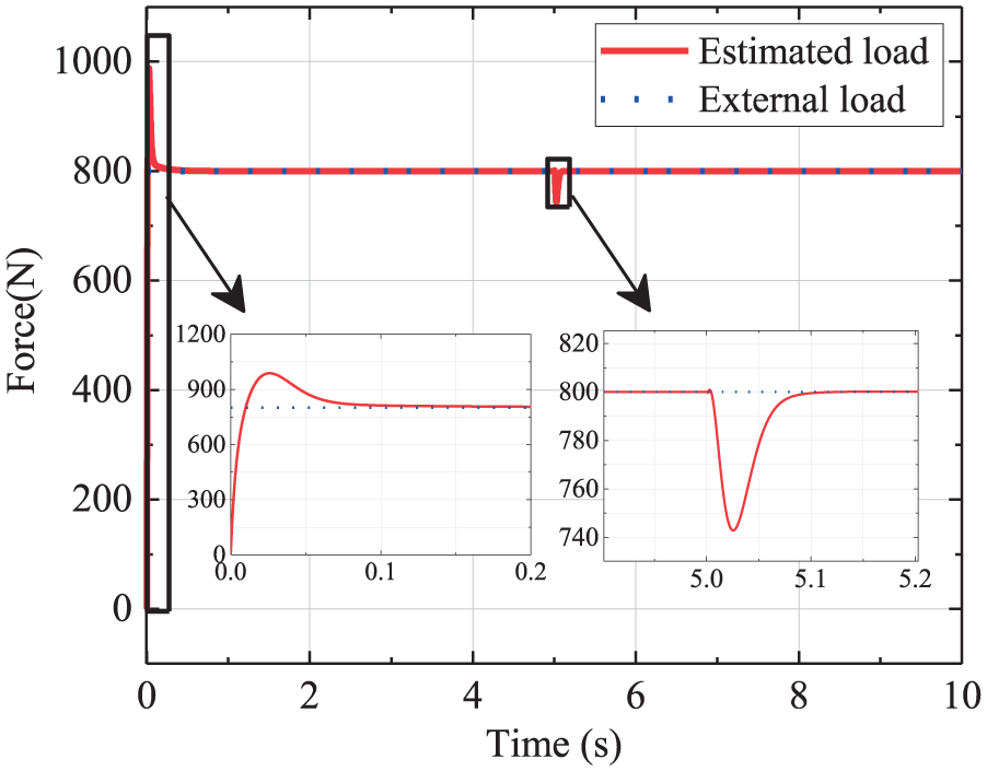
Estimated force under a step command.
Taking the command displacement xd = 0.005sin2t + 0.02 (m) and the load force Ft = 800 N, Figures 12 and 13 illustrate the tracking performance of the DOB to the continuous command.

Tracking error under continuous command.

Controller output under a continuous command.
Figure 12 indicates that the DOB-based system with the maximum error of no more than 0.05 mm tracks better than the conventional PID system with that up to 0.47 mm. Figure 13 depicts that, for a large error, DOB can produce a signal with sufficient value to allow the actuation cylinder to approach the command displacement quickly. Figure 14 shows that the static friction has greater influences on the target cylinder with low speed, especially at the moment when the velocity direction changes.

Estimated force under a continuous command.
In addition, the DOB includes an inner pressure to improve robustness of the system in case of variable external load. The following results are obtained taking the load Ft = 200sin2t + 800 (N) and the command displacement of 20 mm. Figure 15 illustrates that, without pressure feedback operator, the PID controller gives rise to large displacement turbulence and a maximum error of 0.13 mm under the preset load change. Figure 16 shows that, using DOB-based control system, the actuation force by the actuation cylinder tracks the varying load very quickly, and the displacement offset is smaller under the varying load, which verifies that it can bring about good robustness.

Displacement of the actuation cylinder under continuous load change.

Actuation force of the actuation cylinder under continuous load change.
All above leads up to positive effects that using the DOB feedback control, response speed, and precision of the actuation cylinder can be raised and that robustness of the system can be improved to resist the hose volume variation resulted from external load disturbance.
Conclusion
A miniature volume-controlled hydraulic system is a feasible solution for compact, flexible, and portable actuation, where two cylinders and long hoses are used to achieve volume control and easy assembly and disassembly.
For a miniature hydraulic actuation system, hoses are indispensable to realize compact and flexible arrangement. However, hose can widen the no-response stage of the miniature cylinder and discourage oil pressurization in the actuation chamber, though it can dampen turbulence of the displacement of the actuation cylinder and actuation pressure.
The DOB-based control approach using Lyapunov theory can achieve a stable system. Comparing to conventional PID, the system using DOB exhibits higher precision and better dynamic performance.
In terms of disturbance rejection ability, the miniature hydraulic actuation system using DOB is superior to that using PID. The inner pressure control circuit allows actuation force of the actuation cylinder to track the load change very quickly and also has quite small displacement tracking error of the actuation cylinder in case of varying external load. The control approach proposed in this article substantially offsets the long hose effect on the actuator.
Footnotes
Appendix 1
Appendix 2
Simulation parameters.
| Parameter | Value |
|---|---|
| T 1 | 3.03 × 10⁻³ |
| T 2 | 1.96 × 10⁻³ |
| m | 50 kg |
| A P1 | 3.77 × 10⁻⁴ m2 |
| A P2 | 4.91 × 10⁻⁴ m2 |
| A A1 | 3.14 × 10⁻⁴ m2 |
| A A2 | 2.01 × 10⁻⁴ |
| β e | 1 × 10⁹ Pa |
| k | 1.03 × 10¹¹ m3/N |
| r | 0.003 m |
| l | 10 m |
| k 11 | 6 × 10⁵ |
| k 12 | 5000 |
| k 2 | 1 × 10⁶ |
Handling Editor: Mario L Ferrari
Declaration of conflicting interests
The author(s) declared no potential conflicts of interest with respect to the research, authorship, and/or publication of this article.
Funding
The author(s) disclosed receipt of the following financial support for the research, authorship, and/or publication of this article: This work was supported by the Foundation of Graduate Innovation Center in Nanjing University of Aeronautics and Astronautics (no. kfjj20160214) and, in part, by the Open Foundation of the State Key Laboratory of Flow Power and Mechatronics Systems under grant GZKF-201613 and the National Natural Science Foundation of China under grant 51575257.