
Abstract
Subgrade bears both the impacts of the high-speed train and the weight of superstructures. Its stability affects the line smoothness directly, but it is very hard to simulate its working condition, and the in situ testing method is inadequate. The article presents a railway roadbed in situ testing device, and it proposes an excitation hydraulic cylinder system to output static and dynamic pressure simultaneously in order to simulate the force of the train. The dynamic following performance is quite poor without control algorithm, so the robust control block is adopted to improve the following performance of the excitation system under different frequencies and waveforms. In addition, considering the effects of the external disturbances, simulation is carried out with a certain intensity of noise to test the effectiveness of the control scheme. The simulation results show that the robust control algorithm makes the excitation system achieving much better following performance.
Introduction
Subgrade is a critical part of the high-speed rail system; it withstands not only the static pressure of the superstructures but also the dynamic pressure of the repeated changes with wheels’ movement.1,2 Its stability directly affects the smoothness of the superstructures and concerns the life and property safety of passengers.
Generally, in order to solve the above problem, numerical simulation in situ testing and laboratory testing methods are adopted. There are so many control schemes such as conventional proportional -integral -derivative (PID), 3 variants based on fuzzy PID4–8 to overcome the linear characteristics of the conventional excitation system. Zheng et al. 9 developed a valve-controlled cylinder excitation system and an adaptive model following control (AMFC) algorithm without consider external disturbances. Thus, considering the uncertainty factor in control plant, robust control schemes10,11 have a widespread applications in industrial fields. Pradana et al. 12 addressed the stabilization of a model helicopter in a hover configuration subject to parametric uncertainty and external disturbances using robust H-infinity control theory. Akmeliawati et al. 13 presented a development of robust controller to solve the major challenges associated with the deployment of autonomous small-scale helicopters in civilian unmanned aerial vehicle applications. Tijani et al. 14 developed a multi-objective differential evolution (MODE)-based extended H-infinity controller for autonomous helicopter control and the article addressed the challenges involved in selection of weighting function parameters for H-infinity control synthesis to satisfy conflicting stability and time-domain objectives. Tijani and Budiyono 15 presented a through procedure to design an extended H1 robust control of dynamic system especially to parametric uncertainty. At the same time, there are few methods for in situ testing railway roadbed stability except the application in the dynamic stability field test (DyStaFiT) system 16 and the AMFC algorithm.9,17 Both the DyStaFiT and the AMFC systems have some shortcomings. Their excitation waveform is simple and has many distortions, what is more, it has poor performance of anti-load variation capabilities.
For these problems above, the article develops an improved control structure and a valve control cylinder drive system and studies the static state characteristic and the dynamic pressure in both high frequency and different waveforms. First, the mathematical model of the excitation system is derived, and the exciting force and the waveform can be adjusted online. Simulation with different signals is carried out to verify the effectiveness of the robust controller. The following performance of the system with the mixed sensitivity H-infinity robust control can simulate the load to subgrade and contribute to high-speed rail research.
Mathematical model of the excitation system
The principle of the excitation system
Traditional mechanical method has a big vibration quality, bearing loss seriously, and low frequency, so it is difficult to meet the development of high-speed rail. Therefore, valve-controlled cylinder and pump control motor are two relatively advanced vibration modes. However, the pump control motor is essentially still based on the inertia vibration principle and it cannot effectively solve the problem above. A new valve–controlled hydraulic cylinder vibration mode is chosen to overcome the above shortcomings; the principle of the valve-controlled cylinder system is shown in Figure 1. The hydraulic cylinder consists of a static pressure cylinder in parallel with a dynamic pressure cylinder. The static force cylinder is controlled by static load, and the dynamic force cylinder is controlled by a pressure servo valve or flow servo valve. The valve-controlled cylinder model of vibration system can adjust vibration parameters online, largely improve the vibration frequency by improving the performance of the servo valve and changing the control strategy, and consequently, it can simulate various working conditions by superposition of two waveforms to imitate the dynamic load of the train. The parallel exciting servo hydraulic cylinder is the core of the system.

Principle of the excitation testing system.
The requirements of the excitation system are shown in Table 1. Output waveform can be controlled through computer. The dynamic valve can be switched from closed-loop force to closed-loop location control system. The excitation frequency is 1–40 Hz and adjustable. When it is closed-loop force control system, the output force is 200 ± 100 kN. When it is closed-loop displacement control system, the output displacement at 1 Hz is ±20 mm and at 40 Hz is ±0.5 mm. The electro-hydraulic servo valve is a complex component and plays an important role in the whole system. One servo valve loads static pressure on the static force cylinder and the other provides dynamic load on the dynamic force cylinder. The performance of the servo valve directly affects the whole system. In order to realize the requirements, the parameters of the two servo valve are shown in Table 2.
Parameters of the excitation system.

Parameters of two servo valve.

Analysis and modeling of the excitation system
Due to the high natural frequency of the hydraulic load of the system, the load can be equivalent to a mass–spring system and the transfer function of the servo valve is considered as a second-order oscillation link. The electro-hydraulic dynamic servo excitation system designed in this article is a driving force control system. The transfer function is described as follows

where

The mathematics transfer function of the valve-controlled cylinder is

where
Because response frequencies of the servo amplifier and the sensor are much higher than that of the system, they can be simplified as proportion link. After analyzed and simplified the elements of excitation system,
18
the block diagram of the excitation system is derived as shown in Figure 2, where


Block diagram of the open-loop system.
Robust control schemes
In many industrial applications, conventional control schemes such as PID and fuzzy PID are widely used. Comparing with traditional control methods, the robust control schemes have its advantages which makes it more application in nonlinear control systems with uncertain and fuzzy factors, overcomes the defeats of classical control theory over-dependent on the accurate controlled mathematical model. We present robust control method for approximate linear servo control cylinder loop to improve its following performance. Its aim is to make the system output to approach to the reference model output. It can not only eliminate the effect of disturbances but also can be applied to the hydraulic system to realize the adaptive control.
The mixed sensitivity
Introduction of the mixed sensitivity H-infinity robust control
The standard

where
Assumed a linear time invariant system that shown in Figure 3,
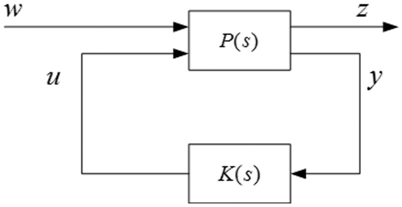
Block diagram of a linear time invariant system.
The generalized object

According to Figure 3 and equation (6)


If

The transfer function matrix

Equation (11) is called the linear fractional transformation. The system which can use linear fractional transformation to represent its transfer function is able to convert to standard H-infinity control problem.
Theoretical background of the mixed sensitivity H-infinity control
The closed loop of the following control system is shown in Figure 4,

The closed loop of the following control system.
When there is no external disturbance (

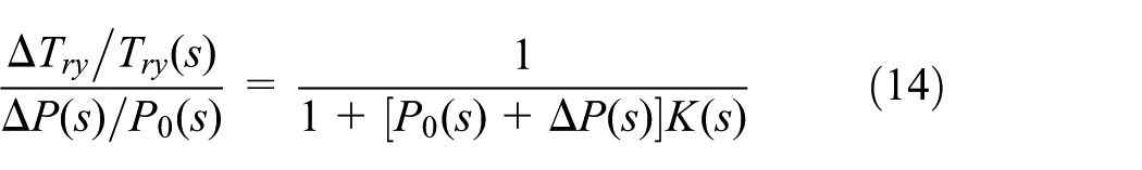
Now consider the changes of

The formula (13) is rearranged as follows
When

When there is no external disturbance (

The calculation above considered the following performance, capacity of resisting disturbance, and the robust stability of the excitation system, but the improvement of the three kinds of performance at the same time is a contradictory problem; therefore, the mixed sensitivity optimization problem arises. H-infinity mixed sensitivity control has been widely used, and it can be simplified into a standard H-infinity control problem.
The mixed sensitivity


Schematic of mixed sensitivity

The transformed standard
Rewrite equation (17) contains two input variables and two output variables
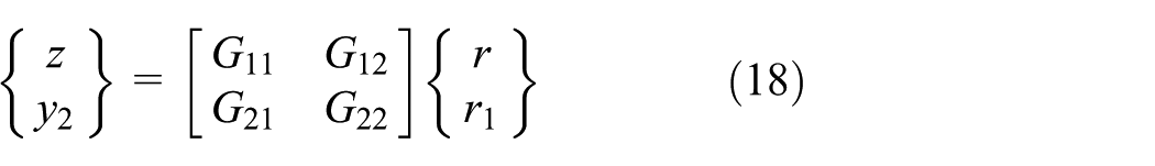
The closed-loop matrix

Expanded equation (19) and the standard

Three weighting functions play a critical role in ensuring good performance of the designed
Design of the mixed sensitivity H-infinity control
Electro-hydraulic servo vibration system is shown in Figure 2; it can be seen that the controlled object is a five-order system. Because the order of the robust controller is equal to the order of the controlled object plus the weighted function order, so the order of the robust controller is 7. There are two methods to reduce the robust controller order: (1) reduce the order of the controlled object and (2) reduce the order of the robust controller. Here we chose the first method. The response frequency of the servo valve is much higher than the response frequency of the hydraulic cylinder, so we simplified the servo valve link as proportional component to reduce the order of the
The contrast curve of the before and after simplification.
The controlled object after simplification

Three weighting functions are selected based on the following objectives:


Three weighting functions are selected based on the experience and trial-and-error approach


Using the robust toolkit function, the mixed sensitivity

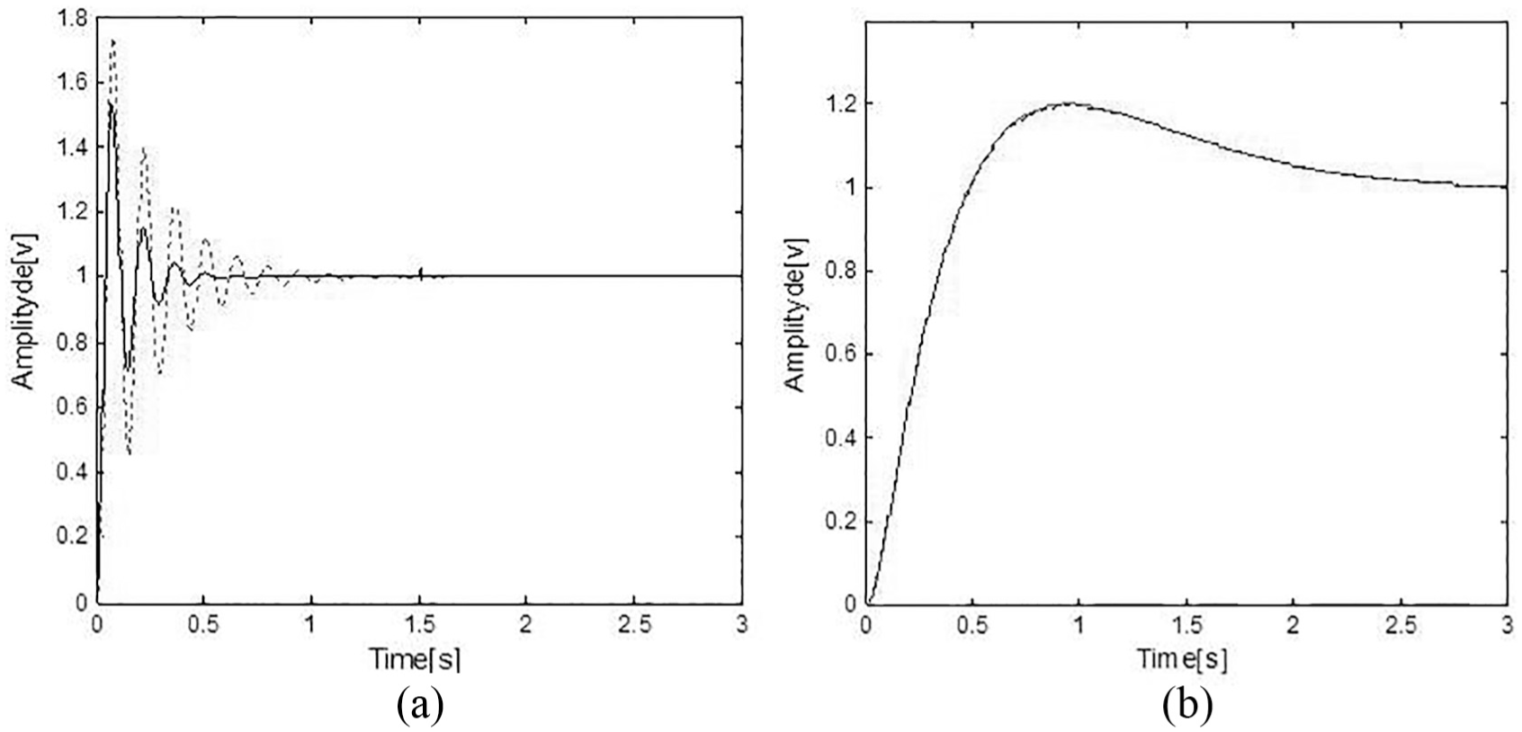
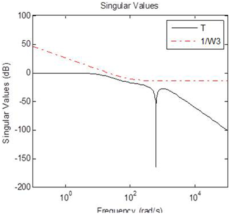
As shown in Figures 8 and 9, the sensitivity and complementary sensitivities responses stay below

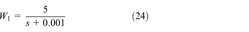
Weighting function
Weighting function
Simulation
Here, simulation model is developed using equations of the excitation system given in section “Mathematical model of the excitation system” in order to verify the effectiveness of the mixed sensitivity H-infinity control. To show the outstanding tracking performance of the mixed sensitivity H-infinity control, simulation is carried out with sinusoidal signals, square signals, and sawtooth signals and the frequencies are 10 and 30 Hz, respectively. Meanwhile, the same signals with a certain intensity of white noise are used in the simulation model.
Simulation without the mixed sensitivity H-infinity control
The signals response curves without the mixed sensitivity H-infinity control are shown in Figure 10, where the red dashed curve is the input signal and the black curve is the signals response. It can be seen that when the system is uncorrected, the signals response waveform distorts seriously and lags much, and it distorts more severely when the frequency increases. Therefore, the system cannot be used directly and should be appropriately corrected to improve the response performance.

System responses without the mixed sensitivity H-infinity control in different frequencies: (a) sinusoidal response, 10 Hz; (b) sinusoidal response, 30 Hz; (c) square response, 10 Hz; (d) square response, 30 Hz; (e) sawtooth response, 10 Hz; and (f) sawtooth response, 30 Hz.
Simulation with the mixed sensitivity H-infinity control
The signals response curves with the mixed sensitivity H-infinity control are shown in Figure 11. It is clear that with the mixed sensitivity H-infinity control, the system is of good following performance.

System responses with the mixed sensitivity H-infinity control under different frequencies: (a) sinusoidal response, 10 Hz; (b) sinusoidal response, 30 Hz; (c) square response, 10 Hz; (d) square response, 30 Hz; (e) sawtooth response, 10 Hz; and (f) sawtooth response, 30 Hz.
Simulation under a certain intensity of white noise
It is well known that rail irregularity is the main external excitation to the subgrade, and its effect to the subgrade can be considered as a random process. To simulate its effect, a certain intensity of white noise (20 dB) is added to the model to verify the effectiveness of the mixed sensitivity H-infinity control. Comparison of system responses with respect to different control input single and frequency as shown in Figures 12 and 13. The rmses (root mean square error) of system response without the mixed sensitivity H-infinity control are 0.5336, 0.8311, 0.8853, 3.6323, 4.7375, 2.3851 on sinusoidal response (10 Hz), square response (10 Hz), sawtooth response (10 Hz), sinusoidal response (30 Hz), square response (30 Hz), sawtooth response (30 Hz), respectively. The rmses (root mean square error) of system response with the mixed sensitivity H-infinity control are 0.4759, 0.7812, 0.5122, 0.7304, 1.0672, 0.6354 on sinusoidal response (10 Hz), square response (10 Hz), sawtooth response (10 Hz), sinusoidal response (30 Hz), square response (30 Hz), sawtooth response (30 Hz), respectively. Compared Figures 11 with 13, it can be seen that the system with the mixed sensitivity H-infinity control still maintains a good following performance with external disturbance.

System responses without the mixed sensitivity H-infinity control in different frequencies with a certain intensity of white noise: (a) sinusoidal response, 10 Hz; (b) sinusoidal response, 30 Hz; (c) square response, 10 Hz; (d) square response, 30 Hz; (e) sawtooth response, 10 Hz; and (f) sawtooth response, 30 Hz.

System responses with the mixed sensitivity H-infinity control in different frequencies with a certain intensity of white noise: (a) sinusoidal response, 10 Hz; (b) sinusoidal response, 30 Hz; (c) square response, 10 Hz; (d) square response, 30 Hz; (e) sawtooth response, 10 Hz; and (f) sawtooth response, 30 Hz.
Conclusion
In the article, we develop an improved control structure and a valve control cylinder drive system for the high-speed railway in situ testing system and study the static state characteristic and the dynamic pressure in both high frequency and different waveforms. To meet the requirement of the improvement of the system’s frequency response and realization of the high-frequency vibration, the article presents a mixed sensitivity H-infinity robust control to improve the system’s frequency response to simulate the load to subgrade. Several conclusions are as follows:
The dynamic response of the uncorrected system of the high-speed railway in situ testing system is very slow and lags much, so it can hardly be used directly.
Controlled by the mixed sensitivity H-infinity control, the following performance of the hydraulic servo excitation system improved a lot.
The system responses with the mixed sensitivity H-infinity control are insensitive to interruption and they can meet the requirements basically.
The weight functions are selected based on the experience and trial-and-error approach; optimization algorithm may be used in the future research to address the selection of weighting functions.
Footnotes
Appendix 1
The requirements of the excitation system are shown in Table 1, according to the table, when at 1 Hz, the amplitude of the system is about 20 mm, when reaches 40 Hz, the amplitude is about 0.5 mm. Usually the piston stroke is designed more than twice of the maximum amplitude, so we take the servo cylinder piston stroke
Handling Editor: Anand Thite
Declaration of conflicting interests
The author(s) declared no potential conflicts of interest with respect to the research, authorship, and/or publication of this article.
Funding
The author(s) disclosed receipt of the following financial support for the research, authorship, and/or publication of this article: The authors would like to offer their gratitude to the National Science Foundation of China for their financial support (the grant nos 51027002, 51475338, 51405350 and 51705377).