
Abstract
The mathematical model of valve deformation of hydraulic shock absorber is established using the hybrid method of large deflection and beam deflection. The model can be used for design purposes and helps in developing damping valve based on single disk and shim stack. The model of the hydraulic shock absorber with valve system consists of shim stack and a spring preloaded disk is developed using AMESim. The correctness of the mathematical model of the valve deformation based on the hybrid method and the simulation model using AMESim is verified by the shock absorber bench test, which proves the method proposed in this article is reasonable and reliable. It is significant for reference in the design and development of hydraulic shock absorber.
Introduction
The development of modern vehicle chassis is very fast, and the performance of vehicle chassis is mainly influenced by an appropriate design of suspension systems. 1 The shock absorber is an important part in a car’s suspension, and its damping force characteristic plays a very important role in the safety and the comfort of the vehicle. 2 The throttle valve is an important part in the shock absorber, and its bending deformation directly influences the damping force characteristic of the shock absorber, which affects the performance of the suspension, that is, the ride comfort and the handling stability of the vehicle. 3 Each valve is characterized by different orifices, located in series or in parallel, which can have constant or variable areas. In particular, the typical variation (which can be observed between low- and middle-high values of piston speed) of the slope of the force versus speed diagram of the shock absorber is due to deformable valves, which are completely closed until a pre-defined pressure drop is reached between their ports.
A single valve can be viewed as a circular thin disk. 4 At present, for the deformation of these types of components, there are two main computational theories: small deflection theory and large deflection theory. Small deflection theory only applies to the small deformation of the valve, which means that the maximum deformation of the valve can not exceed 1/5 of its thickness. When the maximum deformation of the valve is between 1/5 and 5 of its thickness, this range belongs to large deformation, and the valve has geometric nonlinearity. Therefore, it is required to calculate via large deflection theory. So far, there have been numerous studies on the valve deflection of hydraulic dampers. At early stages, Duym et al. 5 and Ventsel and Krauthammer 6 studied theoretical models of the disk stack prediction and interpretation of the fatigue wear process. After that, existing approaches to valve system modeling and measurement data interpretation are being continually improved 7 and the finite element modeling approach is being implemented to support development of more advanced models. YJ Chen 8 and CC Zhou et al. 9 developed a precise mathematical model of the valve deflection using the small deflection theory, but the valve deformation of shock absorber belongs to the large deformation in the actual working condition. With the reduction of the thickness of the valve and the increase of the working load, the error of valve deformation based on deflection theory is also increasing. YD Li and J Li 10 use the Chien perturbation method to solve the valve deformation, but the error is larger. C C Zhou and L Gu 11 utilized finite element method (FEM) to solve valve deformation problem. Though the solution was more accurate, finite element method can not be used in modeling and analysis of the whole shock absorber. LP He et al. 12 have overcome these shortcomings using perturbation method to combine FEM to solve the valve deformation; however, only the maximum deformation of the valve can be obtained. P Czop et al. 13 developed the simplified and advanced models for damper valve system. The valve deflection error obtained from the simplified linear model is large, P Czop et al. used iterative method to solve the problem of simplified the nonlinear model, however, the calculation process is complicated and it is easy to cause errors in process. Meanwhile, P Czop et al. Used finite element method to solve advanced model, and the solution is accurate. A Farjoud et al. 14 studied the method of calculating the deflection of shim stack using energy method and verified the correctness of the model by the shock absorber bench test.
This article will discuss a mathematical model of shock absorber valve based on the hybrid method of beam deflection and large deflection; the model can be applied to analyze single disk deflection and shim stack deflection. The form of this model is simple and easy to solve. And the accuracy of the model is verified by FEM simulation. The hydraulic shock absorber with valve system consists of shim stack and a spring preloaded disk is modeled and simulated using AMESim, 18 and the correctness of the mathematical theory and simulation is verified by bench test of the shock absorber.
Modeling of valve deformation
Modeling of single valve deformation based on beam deflection theory
Figure 1(a) shows a single valve mechanical model under uniform load q, the model can be regarded as a thin disk with fixed inner ring and unconstrained outer ring and its thickness is δ. It can be divided into several sectors with minimal angle (

Model of the single valve: (a) Single valve model under uniform load, (b) The thin disc of several sectors.
The diagram of relationship between deformation and load of the valve after the transformation is shown in Figure 2.

The diagram of relationship between deflection and load of the valve.
As shown in Figure 2, a coordinate system is established where the center of the ring is the origin of the coordinate. The bending moment equation of the section of radius r is

where
According to the formula of the inertia moment of the rectangular section in material mechanics, 16 the section inertia moment at the radius r is

Using the integral method in material mechanics to calculate the beam deflection,
16
the deformable valve deflection

Making

as the deflection coefficient of the deformable valve at any radius, the deflection formula of the deformable valve obtained based on the beam deflection theory can be written as

where E is Young’s modulus (Pa) and
Modeling of single valve deformation based on hybrid method
Because beam deflection theory is derived from the derivation of elastic mechanics theory, it is only suitable for elastic deformation under small load. In the actual working condition, the valve deformation of the shock absorber belongs to small deformation only near the inner edge, and the deformation of valve port belongs to large deformation and it is closely related to damping force characteristics. Therefore, a mathematic model of the valve deformation based on the hybrid method of beam deflection and large deflection is proposed.
According to the mechanical diagram of the deformable valve shown in Figure 1, based on the large deflection theory, the deformation equation of the deformable valve at the outer edge is obtained by the second-order perturbation solution of the Chien perturbation method 11

where
Making

where
Making
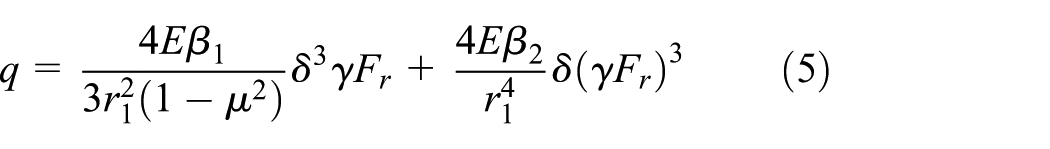
Let

the simplified hybrid method is

Modeling of shim stack deformation based on hybrid method
The actual shock absorber valve system is generally disks in cylindrical or pyramidal stacks. In this article, the model of cylindrical shim stack deflection is mainly studied. Considering the shim stack assembly shown in Figure 3. The shim stack consists of n disks stacked one upon the other. A single valve geometry model shown in Figure 1. The first valve plate is subjected to the fluid pressure acting thereon, resulting in bending deformation, the force is transmitted to contact with another valve, repeating the transmission of force, making the entire shim stack bending deformation. Inter-shim friction is not investigated within this model, although it is suspected to have a contribution to the overall valve hysteresis.

The force diagram of cylindrical shim stack with preloaded spring.
It is known from the literature 9 that each shim deflection of the shim stack is equal, and then the deflections and loads of the shim stack shown in Figure 3 have the following relation


Where
The above n equations are summed to get a model of the shim stack deflection, which is

Equation (7) is a special form of cubic equation with one variable


After the value of

where
The equivalent thickness of the shim stack

With equation (10), the shim stack can be equivalent to a single valve to calculate its deformation.
Numerical simulation verification
The theoretical calculation and finite element simulation are carried out based on the single damping valve, the model of the valve shown in Figure 1 is established by ANSYS, and its boundary constraint and load are shown in Figure 1(a), and the parameters of simulation and theoretical calculation are listed in Table 1.
The main parameters of the valve plate.

Because the deformation of the damping valve is large deformation in the actual working condition, the solution control is set to large deformation when simulating. The results are shown in Figure 4.

Simulation results of the valve deformation based on FEM: (a) deformation distribution on the valve and (b) deflection diagram of the valve.
Figure 4(a) shows the deformation distribution on the valve; the deformation results are illustrated via color contour representing the varying deflection regions. The maximum deflection is 2.9895e–04m, according to equation (6) and the related parameters in Table 1; the calculated maximum deflection of the valve is 2.971e–04m, and the relative deviation is 0.6188% and the error is very small. Figure 4(b) shows the deflection diagram of the valve at any radius, where the origin of the horizontal axis represents the inner radius of the valve. From Figure 4(b), it can be seen that the deflection at the valve port is 1.7653e–04m. According to equation (6), substituting related parameters in Table 1, the calculated deflection at the valve port is 1.6904e–04m, and the relative deviation is 4.24%. Fully meet the practical engineering requirements.
At present, the small deflection theory is widely used to calculate the deformation of damping valve, 17 because only the elastic deformation is considered, and the calculated deformation is larger than the actual deformation of the damping valve. In order to compare the deflection calculated by different methods more intuitively, the deflection curve of the valve based on FEM, the small deflection method, and the hybrid method is plotted, as shown in Figure 5.

Valve deflection diagram of three methods.
From Figure 5, the valve deformation based on the hybrid method has good agreement with the simulation result of FEM, and the error gradually decreases with the increase of deformation. The deformation calculated by small deflection method only has good agreement with the simulation result in a relatively small deformation range, but the error also increases with the increase of deformation. Because only the elastic deformation is considered in the small deflection method, the calculated valve deformation is larger than the actual deformation of the damping valve, which shows that the hybrid model can be used to calculate the valve deformation at any radius, and the small deflection method is only applicable to calculate small deformation of the damping valve.
Simulation using AMESim and test verification of the shock absorber
Structure and principle of the shock absorber
The shock absorber studied in this article is a twin-tube hydraulic shock absorber, and its structure is shown in Figure 6.

Structure of the shock absorber.
The shock absorber has two main working strokes: recovery stroke and compression stroke. The red thick arrows in Figure 6 indicate the direction of the piston rod in the recovery stroke. When the wheel is stretched relative to the body, the piston rod moves outward relative to the working cylinder, and oil flows in the shock absorber, as indicated by the red thin arrows in Figure 6. The damping force caused by friction in the oil and flow through different damping valve hinders the relative movement of the wheel and body. Therefore, the damper plays the role of reducing damping and buffering vibration to improve ride comfort of vehicle.
The motion principle of the shock absorber in the compression stroke is similar to that of the recovery stroke, and only the directions of the piston rod and oil flows are opposite to that of the recovery stroke.
The mathematical model of the shock absorber
The physical model shown in Figure 7 is established according to the structure diagram of the twin-tube hydraulic shock absorber, as shown in Figure 6.

Physical model diagram of the twin-tube hydraulic damper.
Taking the recovery stroke as an example, the parametric model of the damper is established. The

where
By changing the form of the formula, the above damping force equation can also be written as follows

where
The friction mechanism is very complex, according to the damper motion state, there is a mutual conversion between dynamic friction and static friction. The speed of the shock absorber is much higher than the static friction speed range. Therefore, the damper friction force can be simplified to a constant; we found the friction force is 40 N when the speed is 0.001 m/s, the value of the friction force can be substituted in equation (11).
Equation (12) permits to compute gas pressure by adopting an adiabatic approximation

where
Damping characteristic before the valve opens.
Figure 8 shows hydraulic circuit diagram before the damping valve opens. The damping valve is completely closed until the pressure drop between Port 1 and Port 2 reaches the pre-defined pressure. The piston rod speed is less than the initial opening valve speed; the valve does not have deformation, oil flows from upper chamber to lower chamber through piston orifices, constant orifices and piston gap, resulting in throttling pressure. In addition, because the recovery chamber has a piston rod, the fluid flowing into the compression chamber from the recovery chamber is not enough to fill the volume increased by the compression chamber, a certain negative pressure is generated in the compression chamber, the pressure difference between chamber 3 and chamber 2 deforms the compensating valve, and the oil flows into chamber 2 from chamber 3. The stiffness of the compensating valve is small and can be considered as a check valve, which can be deformed by the small oil pressure. Only in this way can oil flow to chamber 2 in time, in order to avoid distortion of the compression stroke.

Hydraulic circuit diagram before the damping valve opens.
According to the pressure drop and flow relationship across two orifices in series or in parallel, 15 there is the following relationships between flow and pressure of piston

where
According to fluid mechanics theory, the pressure–flow relationship can be written in the following form
where
The constant orifice is a small rectangular orifice in a symmetric form, and its equivalent diameter d is computed according to the equal velocity flow method

where
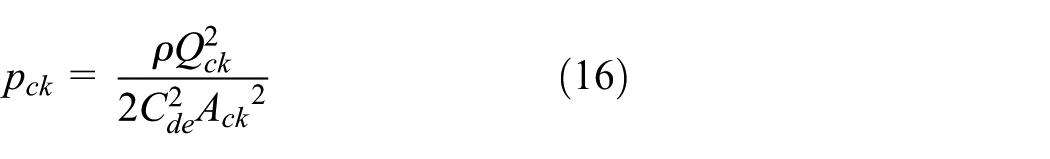
where
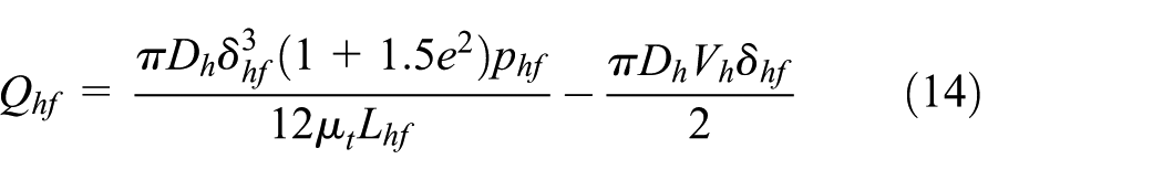
The piston orifices distribute on the piston evenly, the diameter of each orifice dhk and the numbers of orifice nhk are standardized, when the length lhk is four times bigger than diameter dhk, the piston orifice is slender orifice. The relationship between flow rate and pressure can be written as
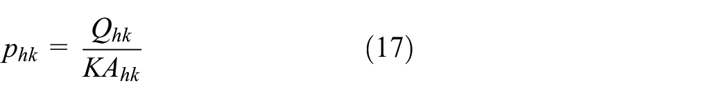
where
The following relations can be obtained by equations (13), (14), (16), and (17)

where

We can utilize equation (18) to calculate the equation between the velocity
2. Damping characteristic after the valve opens first.
Before and after the Reb. valve opens first, hydraulic circuit diagram of the bottom valve remains unchanged, so there is only the piston hydraulic circuit diagram after the valve opens first, the diagram is shown in Figure 9.

Hydraulic circuit diagram of the damping valve opens first.
According to the pressure drop and flow relationship across two elements in series or in parallel 15 , the equations of flow rate and pressure of hydraulic circuit diagram shown in Figure 9 are

When the pressure drop between Port 1 and Port 2 reaches the pre-defined pressure, the valve deforms at the valve port, creating a circular gap, the relationship of flow rate
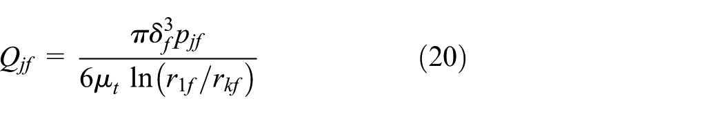
where
The following equation can be obtained by equations (14), (16), (17), (19), and (20)

The relationship between the throttle pressure drop

where
Combining equations (21) and (22), the following equation can be obtained
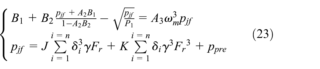
where
Combining equations (14) and (16)–(18), the following relationship can be obtained

Combining equations (23) and (24), the relationship between the velocity and the pressure drop
3. Damping characteristic of the valve opens to the maximum.
The damping characteristic of the valve fully opens is similar to that after the valve opens first, and the hydraulic circuit is shown in Figure 9. The Reb. valve has achieved maximum deformation
Modeling and simulating of the hydraulic shock absorber based on AMESim
The deformation of the damping valve directly affects the damping force characteristic in form of the force–displacement (F-S) and the force–velocity (F-V) diagram. Therefore, the curves of the F-S and the F-V of the shock absorber can be used to verify the correctness of the mathematical model of the valve deformation based on the hybrid method. According to structure and principle of the shock absorber, a model of the hydraulic shock absorber is developed using AMESim, as shown in Figure 10. The spring of varying rate in AMESim is used to simulate the damper valve system. The stiffness of the shim stack and a spring preloaded disk are calculated using the hybrid method, the overall stiffness is taken as the stiffness of the damper valve system and is set as the spring stiffness in AMESim, and spring preload is set in AMESim to simulate the spring preload of the actual damper valve system. The other parameters of the simulation model are set according to the actual parameters of the shock absorber and the above mathematical models, and the main parameters of the shock absorber are listed in Table 2.

Simulation model of the hydraulic shock absorber based on AMESim.
Main parameters of the shock absorber.

Simulation AMESim and test verification
According to QC/T545-1999(shock absorber bench test standard), we input related data into the simulation model and the experiment, then load sinusoidal excitation. Table 3 shows the specific parameters.
Parameters of the loaded excitation.

Some measurements are carried out on a Mechanical Testing&Simulation (MTS) test rig. Through testing the shock absorbers by giving different excitation conditions, Figure 11 shows the damper and the test rig of the damper used in this study, we obtained the multi-working indicator diagram of the shock absorber, the diagram was shown in Figure 12(a). By setting batch parameters in AMESim, we obtained the multi-frequency indicator diagram of the shock absorber, which was shown in Figure 12 (b).

The test rig of the shock absorber.

Indicator diagrams of the shock absorber: (a) simulation curve based on AMESim and (b) test curve.
From Figure 12(a) and Figure 12(b), it can be seen that the indicator diagram of the model is in fairly good agreement with the measurements. There are only small differences existing locally, this may be due to the simplification of the shock absorber during the simulation modeling. Such as the frictional force of the piston master cylinder is not taken into account.
The velocity input characteristics determine whether the test and simulation are performed statically or dynamically. During static simulations and tests, different constant velocities are entered. Table 3 shows the specific input conditions. Figure 13 shows the static simulations and tests results.

Static velocity characteristic curve.
As shown in Figure 13, static damping curves of the simulation and measurement are composed of three parts: low-speed zone, the shape of the low-speed zone is mainly determined by the size of the constant orifice; the knee zone (the region on the right of the knee point), the shape of the knee zone is determined by the opening characteristics of the valve; high-speed zone, starts where the curve blends into a straight line, the maximum size of the opening valve and the preload of the spring are main factors determining the slope of the zone.
As can be seen from Figure 13, the trend of F-V curves in simulation and test are basically the same for the three zones. The simulation and test results are highly consistent for the knee point of the curve (the valve-opening point of the damper). The slope of the curve is slightly different only in the high-speed zone; the simplification of the valve model and the simulation model are the main factors resulting in the difference.
Because the static curve cannot well simulate the dynamic process of the actual work of the damper, the dynamic simulation and measurement of the damper are carried out. In AMESim, the input excitation is set to a standard sine signal. The excitation frequency is 6.34 Hz; the amplitude is ±0.025 m. The test input is same as the simulation input. The dynamic velocity characteristic curve obtained by the simulation and the test are shown in Figure 14.

Dynamic velocity characteristic curve.
Similar to the static damping curve shown in Figure 13, the dynamic curve can also be divided into three zones, for the three different zones, the dynamic damping curve trends in simulation and test are basically consistent. Unlike the static damping force curve, the dynamic damping force curve is circular; the cycle is divided into four different phases: rebound acceleration (Reb. acc), rebound deceleration (Reb. dec), compression acceleration (Comp. acc), and compression deceleration (Comp. dec). According to Figure 14, the acceleration force values are lower compared the deceleration ones around zero velocity, where the movement changes direction, this separation is called “Hysteresis.” According to Figure 14, both the simulation model and the test have hysteresis characteristics in the middle- and low-speed regions, and the only difference is in the relatively low hysteresis level estimated by the simulation model, compared to the actual characteristics of the shock absorber. This is because the simulation model ignores some major factors that cause hysteresis, such as leakage and elastic deformation of master cylinder and friction of inner-shim.
The above analysis shows that the shock absorber simulation model based on AMESim is reasonable and accurate. The model simulates the actual shock absorber well, It also shows that it is feasible to calculate the deformation of the shock absorber valve by the hybrid method.
Conclusion
In this article, based on the hybrid method of beam deflection and large deflection, the mathematical model of the valve deformation is established, the model of the shock absorber with valve system consists of shim stack and a spring preloaded disk is developed using AMESim, and the measurement is carried out by damper test rig. The following conclusions are obtained:
The mathematical model for the valve deformation based on the hybrid method of beam deflection and large deflection is simple and easy to calculate, and the accuracy is high. The model can be used for design purposes and helps in developing damping valve based on single disk and shim stack, which is beneficial to the whole modeling and analysis of shock absorber in practical engineering.
The simulation results show high agreement with experimental results, the proposed AMESim model of shock absorber with valve system consists of shim stack and a spring preloaded disc has high accuracy, which has a certain reference for the development of shock absorber.
The simulation results and the experimental results have some small errors in the local area, mainly because the shock absorber is simplified in modeling. In practical work, the shock absorber is very complex and needs to be studied and improved continuously to improve design level of shock absorber.
Footnotes
Handling Editor: Nima Mahmoodi
Declaration of conflicting interests
The author(s) declared no potential conflicts of interest with respect to the research, authorship, and/or publication of this article.
Funding
The author(s) received no financial support for the research, authorship, and/or publication of this article.