
Abstract
This article deals with an experimental investigation of coinstantaneous heat and mass transfer phenomena between water and air in a counterflow wet cooling tower filled with a new type packing named “FCP-08.” The packing consisted of foamed ceramic corrugated board with sine waves, surface retention groove is 1.0 m high, and it has a cross-sectional test area of 0.68 m × 0.68 m. This investigation is focused mainly on the effect of the water–air mass flow ratio on the heat and mass transfer characteristics of the cooling tower, for different inlet water temperatures. The results show that the cooling water range,
Keywords
Introduction
Counterflow wet cooling towers are widely used in power, chemical, and other fields as important heat exchange equipment; it is used to cool high-temperature water or other medium (here referred to cooling medium) from condensers and process equipment. The cooling medium is pressurized by cooling water pump and sent to the distribution pipe of the cooling tower and then sprayed to the water drenching filler through the nozzle. At the same time, the ambient air is drawn from the bottom of the tower and then passed through the packing layer; due to the pumping action of the tower, the air passes through and the heat exchange between the packing layer and cooling medium is fully carried out. In counterflow cooling towers, the hot water is sprayed into the air stream. The enthalpy of water decreases during the heat and mass transfer, while that of air increases. 1 The efficiency of the cooling tower is closely related to the heat and mass transfer characteristics.
The packing may be qualified as the heart of the cooling tower, and its thermal performance has an important influence on the heat transfer efficiency of the cooling tower. The material of packing has great influence on its thermal performance as it provides a very large surface area for evaporative heat and mass transfer to take place from hot water to the surrounding air and increases the contact time between the two fluids. In this respect, with the development of materials science and manufacturing process, various types of packing have been designed over the years and the researches have been pursued in this field in order to improve the transport phenomena in these equipments and therefore enhance their performances.
Since the early 40s, Simpson and Sherwood
2
studied the working performance of mechanical ventilation cooling tower with 1.05 m wood slats packing. They give data for several different tower designs over a range of performance conditions. These data were later correlated by Braun
3
in terms of the number of transfer units (NTUs) as a function of the water–air mass flow ratio
The main purpose of this article is to carry out an experimental investigation of the heat and mass transfer phenomena observed inside a counterflow wet cooling tower filled with an “FCP-08”-type packing. This type of packing which has been initially developed and used in catalyst carriers, porous media combustion, biofilters, and biotrickling filters (reported in the literature11,12) has not been used in cooling water systems using direct contact between water and air. Based on the above considerations, this article analyzes the cooling water range, the efficiency of the cooling tower, the cooling characteristic coefficient, and the heat rejected by the cooling tower with the change in the inlet water temperature and the water–air mass flow ratio, which can provide reference for the engineering design and the application of foam ceramic packing cooling tower.
Experimental materials and devices
Packing materials and structure
Packing materials
This experiment adopts the free sintering foam ceramic packing, which uses the method of foam plastic precursor slurry forming, made by curing at room temperature. Its aggregate is powdered aluminosilicate minerals, with a fineness of 325 mesh. The main suspending agent is sodium bentonite, and the auxiliary suspending agent is carboxymethyl cellulose (CMC); the content of Na is 6.5%–8.5%. The surfactant is JFC (Fatty Alcohol-polyoxyethylene Ethe), the superplasticizer is polycarboxylic acid polymer compound, and the foam plastic carrier is polyurethane plastic foam with an aperture of 8 ppi (i.e. the number of holes per inch or 25.4 mm length); its main ingredient and physical properties are shown in Table 1. Its morphology is shown in Figure 1. The surface of foam ceramic packing was pretreated by applying the water-absorbent resin coating evenly to improve the hygroscopicity and water dispersion of the foam ceramic packing.
The main ingredients (mass fraction) and physical properties of foam ceramic packing.

CMC: carboxymethyl cellulose.
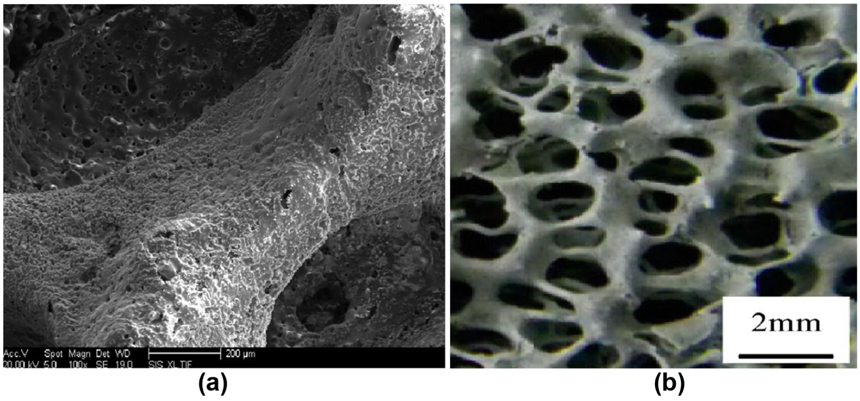
Foam ceramic packing’s morphology: (a) the SEM microstructure of the filler and (b) three-dimensional connected hole network structure of the filler.
Packing structure
The hydrodynamics and heat and mass transfer performance of the packing are closely related to their structures. Foam ceramic corrugated board has three-dimensional connected hole network structure composed of sine wave. The height of the wave is 35 mm. The wave distance is 60 mm, and the inclination of the wave is 50°. Combined with the shape of mature structured packing, we fabricated the “FCP-08” ceramic foam corrugated board packing with binder using the assembly method of sheet layer and layer crossing. The average diameter of the inclined through-hole is 45 mm, as shown in Figure 2. In order to improve the specific surface area of packing and the flow path of water membrane, and prolong the exchange time of the heat and mass, the inner and outer walls of the corrugated plate are pressed to have striated retention grooves. The retention groove is perpendicular to the height direction of the through-hole, and the average depth of the retention groove is one-third of the thickness of the packing.

FCP-08 packing block’s structure: (a) inclined through-hole structure of the packing and (b) surface structure of foam ceramic corrugated board.
The structural characteristics of the packing are characterized by specific surface area and effective porosity. The specific surface area refers to the surface area of the packing per unit volume, and the effective porosity refers to the total volume of voids that are interconnected in the packing per unit volume. In this experiment, the above parameters of “FCP-08” foam ceramic corrugated board packing were measured by Autosorb-3B nitrogen adsorbent instrument using the method of Brunauer–Emmett–Teller (BET) nitrogen adsorption capacity. The main structural parameters are shown in Table 2.
FCP-08 foam ceramic corrugated board packing block’s structural parameters.

By analyzing the data in the table, it can found that the value of specific surface area and porosity of “FCP-08” packing are relatively high. This is because the packing is made of foamed ceramic corrugated board in a crossed manner. Except for the formation of larger through-hole, the foam ceramic corrugated board itself has a special three-dimensional connected hole network structure, making the specific surface area and the porosity of the packing increased significantly.
Experimental devices and the processes
The thermal and mass transfer experiment device of the foam ceramic packing cooling tower established in this study is shown in Figure 3. It mainly includes thermostatic water tank with an electric heater (1), circulating water pump (2), electromagnetic flow meter (3), water distributor (4), cooling tower with “FCP-08” packing (5), collecting pool (6), centrifugal blower (7), air distribution chamber (8), air inlet heater (9), steam humidifier (10), air inlet rectifier grid (11), drift eliminator (12), thermostat (13), electric heater (14), bypass pipe (15), filter (16), temperature measuring device (17), differential pressure measuring device (18) (inclined tube pressure gauge), water tank feed inlet (19), and a number of valves. In order to improve the visualization degree of the experiment, the cooling tower body is assembled with transparent Plexiglass plate. The external structural size of the tower body is 700 mm × 700 mm × 2500 mm, and the size of the “FCP-08” packing inside the tower is 680 mm × 680 mm × 1000 mm. The cooling tower adopts tube pressure water distribute, the water distributor consists of five equally spaced DN50 steel tube, the bottom of each steel tube is equally spaced with an opening hole and equipped with a nozzle, and the diameter of the hole is 7 mm.

Experimental apparatus for heat and mass transfer of ceramic packing cooling tower.
The work flow and principle of the experiment are as follows: when spray water in the constant temperature water tank is cyclically heated to the set spray temperature into the tower, it flows through the circulating pump and the flow meter into the top of the cooling tower. After measuring the inlet water temperature
As shown in Figure 3, the dry and wet bulb temperatures in the inlet and outlet of the cooling tower are measured by a digital wet and dry bulb thermometer, the inlet and outlet water temperatures of the cooling tower are measured by platinum resistance temperature sensor, and the sensor is installed in the inlet section of the spray water temperature measurement casing and the pipeline from the collecting pool to the constant temperature water tank; each temperature is measured by multiple PT100 sensor nodes and the measurement results are averaged; the flow rate of spray water is measured by electromagnetic flow meter. The parameters of the experimental test instrument are shown in Table 3.
Experimental test instrument parameters.

By adjusting the fan frequency converter to change the inlet air flow rate, the wind speed of measuring points in the cross section of the outlet straight pipe of the cooling tower is measured by the hot-wire anemometer using the method of homolographic stationing;
13
taking the arithmetic average of the wind speed of each measuring point as the average outlet wind speed, the air mass flow rate

In order to ensure the intuition and comparability of this experiment, the inlet air dry and wet bulb temperatures of the cooling tower should be stably unchanged. In the course of the experiment, the water–air mass flow ratio and inlet water temperature are independent variables. As for the water–air mass flow ratio, considering the convenience of adjusting, the change is mainly achieved by controlling the inlet air mass flow rate to be constant and adjusting the mass flow rate of the spray water. In practical engineering applications, it is generally believed that the inlet water temperature is the dependent variable and only varies with other independent variables such as the heat load of the condenser or the mass flow rate of the spray water. However, in this experiment, the heat load has been independent, and the mass flow rate of the spray water remains unchangeable under the same work condition, thus the inlet water temperature can be taken as independent variable. The experimental research consists of 21 tests obtained by modifying the water mass flow in seven levels and the inlet water temperature in three levels. The mass flow rate of the spray water takes 7.0, 8.0, 9.0, 10.0, 11.0, 12.0, and 13.0 m3/h, and the inlet water temperature of the cooling tower takes 32°C, 35°C, and 38°C.
Experimental uncertainty
Considering uncertainties of individual instruments, it is significant to study their effect on the final result. The relative uncertainty is expressed as follows 14

In this article, uncertainties involved in different instruments used in this experiment for measurements are evaluated as follows
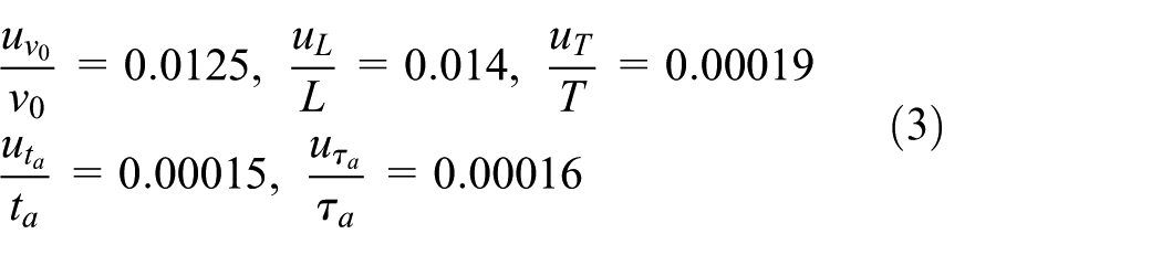
Using equations (2) and (3), relative uncertainties involved in different performance parameters based on experimental results can be calculated as follows

Heat and mass transfer phenomena in the cooling tower
Cooling characteristic coefficient
In the packing of the cooling tower, the flow of water is dominated by gravity, and the flow of air depends on the natural convection. While the gas and water are carrying on the sensible heat transfer, the evaporative cooling is also carried out by absorbing the latent heat of vaporization due to the evaporation of water. The enthalpy difference method proposed by Michael united the heat transfer formula with the difference of temperature and concentration as the driving force to a heat transfer formula with the difference of enthalpy as the driving force.
15
Merkel introduced the Lewis relation

The heat dissipation of water can also be expressed by the difference of the water temperature between the inlet and outlet of the packing, modifying the Michael equation by combining the equation of Berman
16
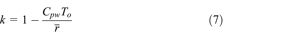
and taking the heat coefficient of evaporated water

According to the literature,
16
the heat coefficient of evaporated water

The heat dissipating capacity of water is equal to the heat absorbing capacity of air in the packing. Combine equation (5) with equation (6) to establish the heat balance equation
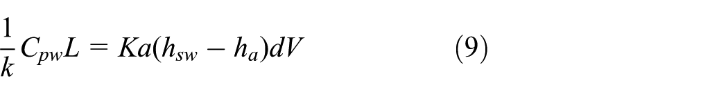
Integrating on both sides of equation (9)
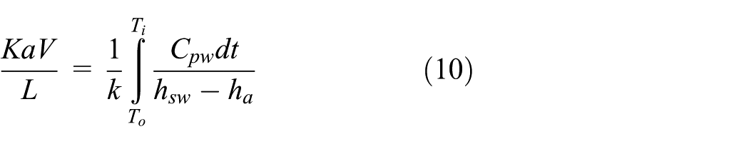
According to Merkel’s
15
method,
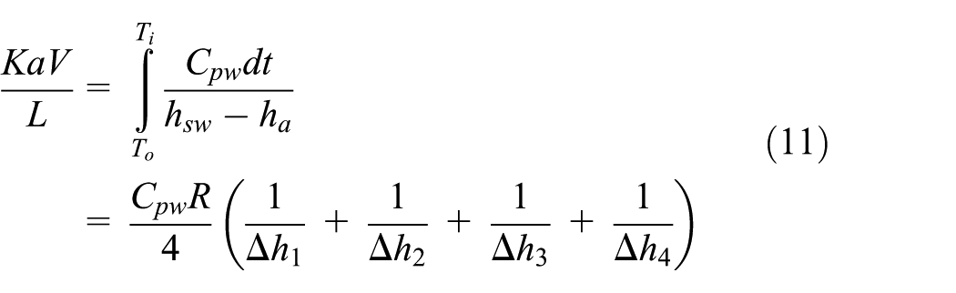

Among them, R refers to the temperature difference between the inlet water and outlet water of the cooling tower, which is known as the range of cooling water, where

Cooling tower efficiency
The cooling efficiency of the counterflow wet cooling tower is usually evaluated by the heat exchange efficiency

In formula (13), the inlet temperature of the spray water
Heat rejected
Considering convective and evaporative heat transfer along with water loss caused by evaporation, Kloppers 18 proposed equation (14) (improved Merkel equation) to calculate the total heat rejected from water

where

Experimental results and analysis
Cooling water range and cooling tower efficiency
Figure 4 shows the variation in the cooling water range,

The variation in cooling water range with the water–air mass flow ratio.
Figure 5 shows the variation in the cooling tower efficiency,

The variation in cooling tower efficiency with the water–air mass flow ratio.
Cooling characteristic coefficient
Figure 6 shows the variation in the cooling characteristic coefficient,

The variation in cooling characteristic coefficient with the water–air mass flow ratio.
As already mentioned, the cooling characteristic coefficient,

The results were then compared with those obtained in the literature for other types of packing. These correlations are as follows:
The correlation given in Armfield Ltd 19

where
Barile et al.’s 20 correlations:
Diameter of the particles, d = 19.05 mm

Diameter of the particles, d = 38.10 mm

where
Kelly and Swenson’s 21 correlation

where
Gharagheizi et al.’s 1 correlations:
VCP
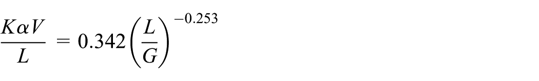
HCP
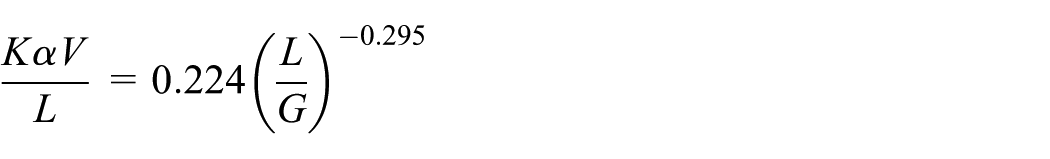
where
Commercial packing with S wave shape

where
The comparison results of the experimental results under the work condition of this article (inlet water temperatures 32°C, 35°C, and 38°C) with the experimental results of other researchers and commercial packing are shown in Figures 7–9. It can be seen that the cooling characteristic coefficient in this research is larger than that of the HCP and VCP, simultaneously, lower than the value in Instruction manual. 19 Figure 8 shows that the cooling characteristic in this research is larger than that of pellicular regime (PR) and bubble and dispersion regime (BDR). 22 In comparison with Kelly and Swenson, 21 it can be seen that when the water–air mass flow ratio is larger than 1, the cooling characteristic coefficient in this research becomes larger than Kelly et al.’s. Figure 9 shows that the cooling characteristic in this research is larger than that of Barile et al.’s 20 and commercial PVC packing with S wave shape. The gap becomes larger with the increase in water–air mass flow ratio. In addition to the difference of packing structure, the height of packing in the experiment, the inlet water temperature, and the weather conditions are also the factors that cause the difference of the cooling characteristic coefficient.

Comparison of cooling characteristic coefficient at 32°C.

Comparison of cooling characteristic coefficient at 35°C.

Comparison of cooling characteristic coefficient at 38°C.
This indicates clearly that the heat and mass transfer coefficients of the packed cooling tower used in this investigation are much higher than other types. The “FCP-08”-type packing has better water cooling capacity. The reason can be attributed to the three-dimensional connected hole structure which connects the two sides’ surface of corrugated plate very well and enhances the horizontal mixing and even distribution of the liquid phase fluid in the packing. Therefore, the cooling performance of the packing is improved. This suggests that cooling tower filled with the “FCP-08”-type packing possesses better heat and mass transfer characteristics and can contribute significantly to energy saving.
Heat rejected
Figure 10 shows the variation in heat rejected by the cooling tower,

The variation in heat rejected by the cooling tower with water–air mass flow ratio.
Conclusion
In this study, evaporative heat and mass transfer inside a counterflow wet cooling tower filled with “FCP-08” foam ceramic packing has been investigated for a wide range of water–air mass flow ratio. The results obtained at different inlet water temperatures, 32°C, 35°C, and 38°C, can be summarized as follows:
The cooling water range,
This article considers the mass change in water caused by evaporation based on the theory of Merkel and selects the calculation method of Bierman. The cooling characteristic coefficient,
The heat rejected by the cooling tower,
Cooling tower filled with the “FCP-08”-type packing compared to systems filled with other types of packing leads to a better performance of heat and mass transfer characteristics and therefore a great water cooling capacity. This can contribute significantly to energy saving and economics.
Footnotes
Appendix 1
Handling Editor: Assunta Andreozzi
Declaration of conflicting interests
The author(s) declared no potential conflicts of interest with respect to the research, authorship, and/or publication of this article.
Funding
The author(s) disclosed receipt of the following financial support for the research, authorship, and/or publication of this article: This research was supported by the National Natural Science Foundation of China (key project; no. 51509076) and the Natural Science Foundation of Jiangsu Province (key project; no. BK20150816).