
Abstract
In order to solve the oversize problem of continuously variable transmission, a rod gear pulse continuously variable transmission is designed. The kinematic mathematical models of key components are established by the matrix method and are simulated by MATLAB in a single phase, based on the analysis of basic structure and working principle of transmission. Also, the length requirements of each rod are studied, and the effect of three adjustment manners on the output-speed is simulated in the single phase. Furthermore, the simulations of the movement law of annular gear are achieved on two conditions of both different phases and different eccentricities on 8-phase. The results show that the manner of adjusting the eccentricity of eccentric wheel is the preferential selection of out-speed regulating method, and 8-phase is an optimal phase of transmission; meanwhile, for the rod gear pulse continuously variable transmission, the variable range of transmission ratio is wider and the pulsation rate is far less than the other traditional continuously variable transmissions.
Keywords
Introduction
Pulse continuously variable transmission (P-CVT) has been regarded as a kind of promising mechanical transmission, 1 but the traditional P-CVT adopts a multi-phase linkage as transmission mechanism, so it has many unavoidable disadvantages, such as high pulsation rate, excessive volume of inertia force, oversize.2,3
In order to improve the transmission characteristic condition of P-CVT, many researchers have been researching on the gear or combining type transmission mechanism. For example, L-X Xu and Y-H Yang, 4 S Li, 5 Heieh, 6 and M Blagojevic et al. 7 study the pin-cycloid transmission, whose variable range of transmission ratio is great; M Ota et al. 8 and S Miyata et al. 9 work on the half toroidal transmission, which has the advantages of strong bearing capacity and low noise; D Nagahata et al. 10 and RG Parker and J Lin 11 research the planetary gears transmission, that is smooth and steady; W Zeng et al. 12 and C-J Liang 13 put forward the combined transmission of ratchet and connecting rod, which realizes the function of zero output and timely adjust-speed; J-X Zhang et al. 14 offer the combined transmission of conical cam and connecting rod, and it has the merits of the stable output-speed and good adjust-speed effect; Z-X Zheng and colleagues15,16 make a search of the combined mechanism of cam and connecting rod, and it overcomes the disadvantages of inertia force and inertia moment; D Li and colleagues17,18 propose a non-coaxial style two-output impulse generating mechanism, which can realize the output of two rocker bars in one motion cycle. The above gear and combination transmissions have their own advantages; however, the problem of oversize has not been solved yet, because the phases of transmission mechanism are located in multiple parallel planes.
The rod gear P-CVT has a combined transmission of eccentric wheel, connecting rod, and ratchet, which adopts multi-phase transmission in a same plane. Furthermore, it solves the problems of oversize and excessive volume of inertia force. The kinematics models of key components are set up by matrix method and are simulated by MATLAB in a single-phase transmission. Meanwhile, the length requirements of each rod are studied, then the effect of three adjustment manners on output-speed is simulated, as well as the simulations of movement law of annular gear on two conditions of different phases and different eccentricities as 8-phase are achieved. The research results can provide theoretical and application references for the design of rod gear P-CVT.
Sketch drawing and working principle
The transmission mechanism of rod gear P-CVT is mainly composed of an input shaft, an eccentric wheel, several connecting rods and swing rods, an annular gear, and so on. The basic structure is shown in Figure 1.
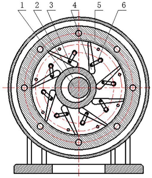
The basic structure of transmission mechanism.
As shown in Figure 1, the input shaft 1 is provided with the eccentric wheel 2, which is connected with the inner ring of rolling bearing 3. There are many connecting rods 4 uniformly distributed around the outer ring of rolling bearing 3, and its bottom keeps in touch with the outer ring by the spring, its top is made into the ratchet to mesh with the annular gear 5, as well as its middle is hinged with the top of swing rod 6 through the pin shaft 7. The bottom of swing rod 6 is fixed on and sway around the fulcrum 8 on the stander. The lower end of pin shaft 7 is in the straight groove 9, so that it can get the straight motion along the groove. The output plate (not marked in Figure 1) is connected with the annular gear 5 by the bolts distributed along the circumferential direction. Furthermore, the axis of input shaft 1, the center of fulcrum 8, and the straight groove 9 are on the same line.
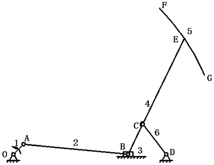
As shown in Figure 2, the schematic diagram of mechanism is drawn. Assuming O, A, B, C, D, E represent the axis of input shaft 1, the center of eccentric wheel 2, the contact point of rolling bearing 3 and the bottom of connecting rod 4, the hinged point swing rod 6 and the middle of connecting rod 4, the hinged point of swing rod 6 and the stander, the meshing point of connecting rod 4 and annular gear 5, respectively.

The schematic diagram of mechanism.
As shown in Figure 2, the rotation of input shaft 1 leads the eccentric wheel 2 and the rolling bearing 3 to rotate around O, driving the connecting rod 4 to swing successively. The connecting rod 4 meshes and impels the annular gear 5 to rotate, under the combined action of rolling bearing 3 and swing rod 6. Moreover, a ratchet mechanism consists of the ratchet of connecting rod 4 and the annular gear 5, and it transforms the reciprocating swing of connecting rod 4 into the unidirectional rotation of annular gear 5. Obviously, the input shaft 1 is the power input component, and the annular gear 5 is the power output one.
Simplification of single phase
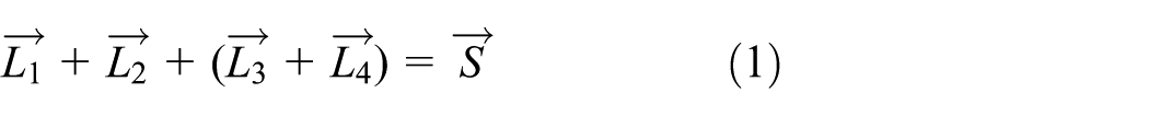
In the rod gear P-CVT, there is a single-phase transmission which is composed of the input shape, the eccentric wheel, a single connecting rod, a single swing rod, and the annular gear, so there are
Before studying the movement law of the whole transmission, a planar four-bar slide mechanism can be equated with the single-phase according to the principle of high pair replaced by low pair. It is shown in Figure 3.
The planar four-bar slide mechanism.
As shown in Figure 3, OA, AB, BE, CD, and FG represent the eccentricities of eccentric wheel, the radius of rolling bearing, the connecting rod, the swing rod, and the annular gear separately. At the same time, OD and OE stand for the lines connecting from the stander and the top point of connecting rod to O point, respectively.
Kinematics models of key components
The planar four-bar slide structure was decomposed into a crank and rocker linkage OABE and a four-bar linkage ODCE, and two closed vector polygons are achieved. In order to build a Cartesian coordinate system, take body frame OD as axis X, and O as coordinate origin. Then assuming that

Two closed vector polygons.
Obviously,

First, the equations for the x-component and y-component of each vector are written and rearranged with the unknowns on the left and the known value on the right, as equation (3)

Then the equations of angular displacements of all key parts are determined in the single-phase mechanism, as equation (4)

Second, supposing

Finally, supposing

Length requirements of each rod
In the crank and rocker mechanism OABE, the length of all rods meets the conditions: (1) the shortest rod is crank; (2) the sum of the length of the longest rod and the shortest rod is less than the sum of others. OA is the shortest one because of the crank, and OE is the longest, as point O is the central point of input shaft and point E may be a point on the annular gear, so


In the ordinary four-bar linkage ODCE, the length of link only needs to meet a condition: the sum of the length of the longest link and the shortest link is less than the sum of others, so


Simulation of transmission characteristics and phase number optimization
An example of the rod gear P-CVT is provided as follows:
Kinematic simulation of key components
According to equations (4)–(6), the simulations of angular displacements, angular velocities, and angular accelerations of the connecting rod, swing rod, and OE are achieved by MATLAB in the process of a single-phase transmission, while the crank rotates one cycle (0–2π). The simulations are shown in Figures 5–7.
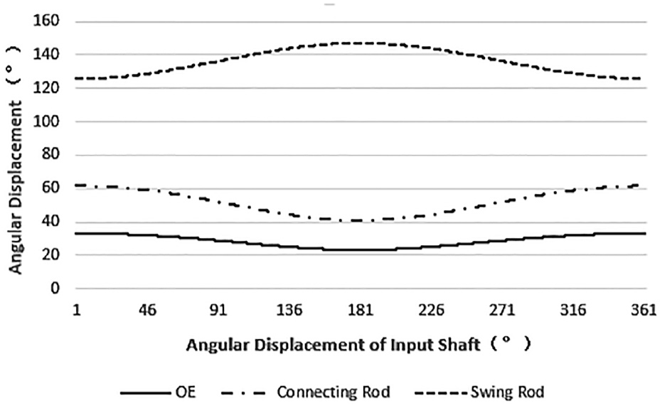
The angular displacements of connecting rod, swing rod, and OE.

The angular velocities of connecting rod, swing rod, and OE.

The angular accelerations of connecting rod, swing rod, and OE.
As shown in Figure 5, the range of angular displacement of three key parts is relatively small in single-phase transmission, and it shows that the required movement path of rods is very short.
As shown in Figure 6, the fluctuation of angular velocities of connecting rod and swing rod exists, which lead to the corresponding vibration of transmission. However, the even number can be chosen and uniformly distributed, so that the motion state of the two phase transmission components opposite to the center of the shaft is completely opposite, and the vibration generated by each other can be counteracted mutually. Therefore, the whole mechanism is relatively stable in the working process.
As shown in Figure 7, the range of angular accelerations of connecting rod and swing rod is relatively large, and it shows that inertia force of transmission is great in the running process. Thus, the optimization of mechanical structure will be further studied to weaken the inertia force in future.
Effect of three adjustment manners on output-speed
The main function of P-CVT is to realize the continuously variable output-speed of mechanism. When the sizes of all parts are determined, the goal would be fulfilled generally by three adjustment manners, namely, changing the eccentricity, the position of hinge point of connecting rod, and length of body frame, it means to change
Changing the size of above key parts needs to meet the requirements listed by equations (7)–(12), so the change ranges of
The length range of three adjustment manners.

It is important to study the variable law of angular velocities of OE with the change of

The effect of three adjustment manners: (a) changing L1, (b) changing L3, and (c) changing L6.
As shown in Figure 8, changing L1, that is, changing the eccentricity has led to the widest adjusting angular velocity range of OE, namely, from 0 to 42 rad/s, so that changing the eccentricity of eccentric wheel becomes the prior selection of the output-speed adjusting method of transmission.
Effect of phase numbers
In transmission mechanism, each connecting rod impels annular gear to rotate successively, and the angular velocity of annular gear is equal to OE in the fastest phase at that moment. According to Table 1, the simulations of the angular velocities of annular gear in different phases transmission are accomplished by MATLAB, when the crank rotates one cycle (0–2π), and the maximum velocity, the minimum velocity, and the average velocity of annular gear can be computed based on the formula, and the transmission ratio and pulsation rate are achieved in all cases, as shown in Table 2.
The transmission ratio and pulsation rate of different phases transmission.
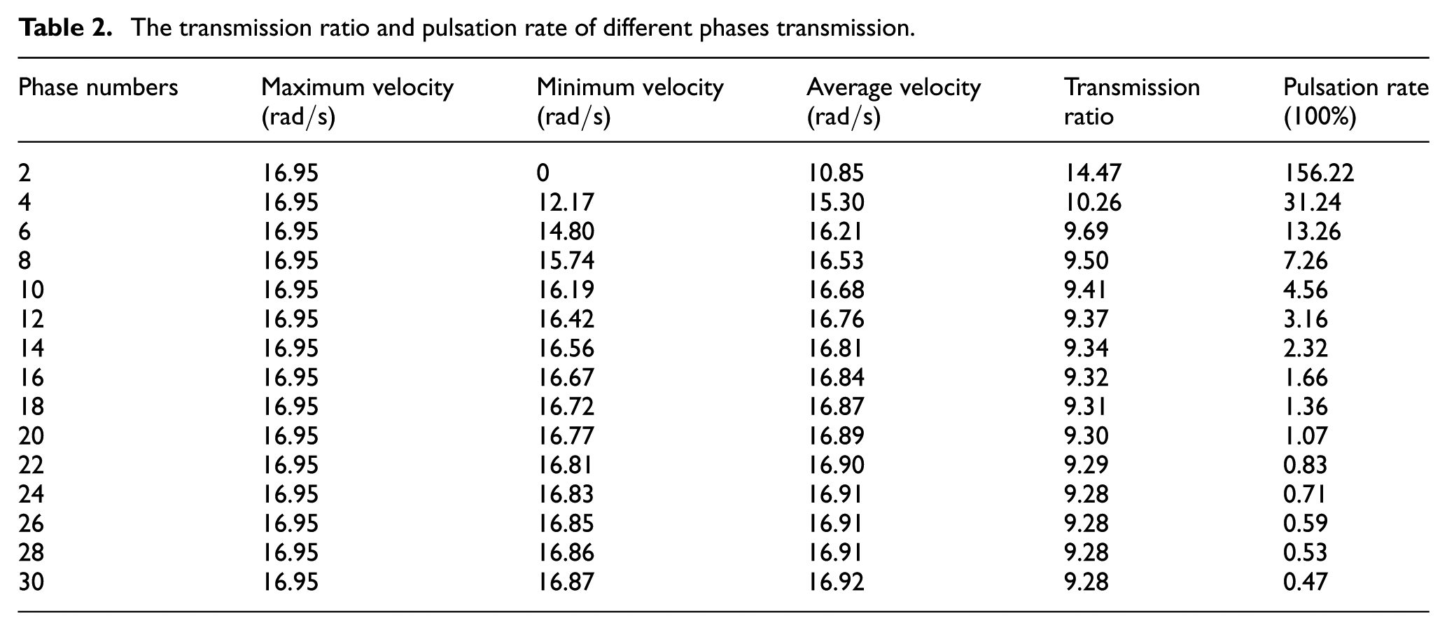
According to Table 2, the combination diagram of transmission ratio and pulsation rate in different phases can be drawn, as shown in Figure 9.

The transmission ratio and pulsation rate in different phases.
In general, the greater the phase numbers, the more stable the superposition curve and then the lower the pulsation rate. But the greater the phase numbers, the more complicated the mechanism, which will be detrimental to the steady operation of P-CVT. According to Table 2 and as shown in Figure 9, the transmission ratios are extremely closed, when the phase number is equal to or greater than 6, and the pulsation rate is less than 8%, when the phase number is equal to or greater than 8. Hence, 8-phase is the optimal phase for transmission through synthetic consideration about the transmission ratio and the pulsation rate.
Influence of different eccentricities
The above studies have proved that the main speed regulating method is to adjust the eccentricity, and 8-phase is the optimal phase for rod gear P-CVT, so the influence of different eccentricities on transmission ratio and pulsation rate is studied on the premise of the 8-phase. The result is shown in Table 3.
The transmission ratio and pulsation rate under different eccentricities.

Two fitting curves of the influence of eccentricity on transmission ratio and pulsation rate are shown in Figure 10, respectively, according to the data in Table 3.

The influence of eccentricity on transmission ratio and pulsation rate.
As shown in Table 3 and Figure 10, the rod gear P-CVT has a wide adjusting range of transmission ratio (from 74.06 to 3.85), and the variable range of pulsating ratio is very small (from 7.49% to 9.42%); moreover, the pulsation rate first decreases and then increases as the increasing eccentricity; especially, when eccentricity is 14 mm, the pulsation rate reaches the highest value of 9.42%. It obviously proves that the range of transmission ratio is much wider and the pulsating ratio is much lower than the traditional P-CVT.
Conclusion
A rod gear P-CVT is designed to solve the oversize problem. The kinematic mathematical models of three key components in a single phase are established by the matrix method, and they are simulated by MATLAB. Meanwhile, the length requirements of each rod are studied; then the effect of three adjustment manners on output-speed is simulated. Furthermore, the simulations of movement laws of annular gear on two conditions of different phases and different eccentricities as 8-phase are achieved. Several conclusions can be drawn as follows:
The movement path of rods required is very short, and the even number can be chosen and uniformly distributed stably on the whole mechanism relatively; meanwhile, the optimization of mechanical structure will be further studied to weaken the inertia force.
There is a widest angular velocity adjusting range of OE by changing eccentricity of eccentric wheel than other adjustment manners, so it is the prior selection of the output-speed regulation manner.
In consideration of the effect on transmission ratios and pulsation rate, 8-phase is the optimal phase choice of transmission than others.
The justification range of transmission ratio is wider and the pulsation rate is much lower than the other traditional continuously variable transmissions; therefore, the rod gear P-CVT is a promising setup which is worthy of further study.
Footnotes
Handling Editor: Hiroshi Noguchi
Declaration of conflicting interests
The author(s) declared no potential conflicts of interest with respect to the research, authorship, and/or publication of this article.
Funding
The author(s) disclosed receipt of the following financial support for the research, authorship, and/or publication of this article: This work was supported by the International S&T Cooperation Program of China and Public Welfare Fund Project of Zhejiang.