
Abstract
The objective of this study was to establish the effects of cold expansion, chamfering, bolt clamping, and their combinations on the fatigue life of an aluminum–lithium alloy single plate. Fatigue tests were conducted to quantify the anti-fatigue effects of the different techniques. A scanning electron microscope was used to perform fracture analyses of the used specimens, and the residual stresses were measured using an X-ray diffraction device. In addition, three-dimensional finite element models of the specimens were established and used to characterize their stress states, and the Smith–Watson–Topper method was used to predict the fatigue lives of the specimens. The fatigue test results showed that all the considered processes improved the fatigue life of the pristine specimen. The most effective was a combination of 3.2% cold expansion, 1-mm chamfering, and bolt clamping using a 6.4-N m torque, which improved the fatigue life of the pristine specimen by a factor of 15.5. The finite element method results also revealed that this combination decreased the maximum stress and confirmed its superiority in relation to the other fatigue-life enhancement techniques in terms of the anti-fatigue effect. The Smith–Watson–Topper method underestimated the specimen fatigue life, but the accuracy satisfied engineering requirements.
Keywords
Introduction
Stress concentration around the edge of a hole in an aircraft structural joint is known to facilitate fatigue cracking,1,2 and most aircraft accidents have been found to be due to fatigue failure. 3 Therefore, the fatigue-life improvement of structural joints is an important subject for aircraft designers.
Various techniques are used in the aircraft industry to improve the fatigue behavior of joints, such as cold expansion, 4 shot peening, 5 laser shock, 6 and interference fitting. 7 Cold expansion is the most commonly used method owing to its convenience and low cost. The process involves the insertion of an oversized mandrel into the joint hole and pulling it out from the other side, resulting in the generation of a beneficial compressive residual stress distribution around the hole. 8 Chakherlou et al. 9 conducted double-shear lap-joint fatigue tests using specimens subjected to varying degrees of cold expansion to investigate the effect of the degree of cold expansion on the improvement of fatigue life. Amrouche et al. 10 established a finite element (FE) model for determining the optimum degree of cold expansion, while Su et al. 11 numerically investigated the effects of single- and double-hole cold expansions on the fatigue life of a 6082-T6 aluminum alloy single plate. Relevant previous works generally involved experiments to confirm the effectiveness of cold expansion for enhancing fatigue life and explained the experimental phenomena by numerical simulation. However, these studies are limited to the effects of the cold expansion degree and alternating load stress level on fatigue-life improvement.
Furthermore, the effect of chamfering and bolt clamping on the fatigue behavior of cold-expanded structures cannot be neglected. Chakherlou et al. 12 performed experimental and numerical analyses of the effects of cold expansion and the application of a clamping torque on the fatigue behavior of 2024-T3 aluminum alloy double-shear lap joints and also examined whether the torque affected the optimum degree of cold expansion. Taghizadeh et al. 13 subsequently used a three-dimensional FE model to capture the residual stress and pre-stress states generated by cold expansion and bolt clamping and predicted the fatigue life of a cold-expanded fastener hole. They found that both cold expansion and bolt clamping positively affected the fatigue life of an open-hole single plate. Jang et al. 14 proposed a new method that involved chamfering of the holes before cold expansion, and the results of its experimental implementation revealed significant fatigue-life improvement compared to cold expansion without chamfering. Rana et al. 15 implemented similar fatigue-life enhancement techniques and conducted fatigue tests to investigate the effect of the chamfer shape on the improvement of the fatigue life of a cold-expanded hole.
However, the above-mentioned works only considered the effect of cold expansion and bolt clamping, or cold expansion and chamfering on fatigue-life enhancement, and not a combination of all three processes, namely, chamfering, cold expansion, and bolt clamping. Building on these previous studies, this study explored methods for enhancing the anti-fatigue effect in a single plate by combining cold expansion, bolt clamping, and chamfering. The objective was to further prolong the fatigue life of a single plate.
In this study, the effects of cold expansion, bolt clamping, and chamfering on the fatigue-life enhancement of a 2297-T87 aluminum–lithium alloy single plate were investigated. Fatigue tests were conducted on six batches of plate specimens of the alloy after using chamfering, cold expansion, bolt clamping, and different combinations of the three processes. Scanning electron microscopy (SEM) was used to define the crack initiation area in sample fracture surfaces. In addition, FE models were generated and used to simulate the fatigue-life enhancement procedure and the fatigue tests, as well as to reproduce the stress and strain fields around holes in the single plate and explain the fatigue test results. The residual stresses in the specimens were measured by X-ray diffraction (XRD) and used to validate the FE simulation results. Furthermore, the Smith–Watson–Topper (SWT) method was used for fatigue-life prediction.
Experiments
Material
The material tested in this study was the third-generation aluminum–lithium alloy 2297-T87. The nominal elemental composition of the material is presented in Table 1, while the σ–ε curve obtained by basic mechanical testing is shown in Figure 1. Young’s modulus and Poisson’s ratio of the material are, respectively, 79 GPa and 0.33.
Elemental composition of Al–Li alloy 2297-T87.


σ–ε curve of 2297-T87 Al-Li alloy.
Fatigue test specimens were extracted from one sheet of an Al–Li alloy plate. The obtained specimens were cut in such a way as to orient the longitudinal load along the sheet rolling direction.
Specimens and test method
To examine the effects of chamfering, cold expansion, and bolt clamping on the fatigue behavior of an Al–Li alloy single plate and determine the best fatigue-life enhancement technique, five different types of fatigue test specimens were considered: (1) open-hole (OH) specimens; (2) cold-expanded (CE) specimens; (3) chamfered–cold-expanded (C-CE) specimens, which were first chamfered and then cold expanded; (4) chamfered–bolt-clamped (C-BC) specimens, which were first chamfered and then bolt clamped; and (5) chamfered–cold-expanded–bolt-clamped (C-CE-BC) specimens, which were first chamfered, then cold expanded, and finally bolt clamped. The details and naming convention of the specimens are presented in Table 2.
Specimen details and naming convention.

The configurations and dimensions of the C and BC specimens are shown in Figure 2(a) and (b), respectively.

Configurations of some test specimens: (a) chamfered specimen and (b) bolt-clamped specimen (dimensions are in mm).
All the specimens were drilled at the center with an initial diameter of 7.85 mm, and the inner surface roughness of the hole was <1.6 µm. In the case of the CE specimens, an oversized mandrel with a maximum diameter of 8.1 mm was pushed into the hole and removed from the other side using an MTS-50 kN pull–push test machine. The contact areas were greased to avoid wear during the process. A cylindrical steel ring device was used to support the specimen on the exit face. Figure 3(a) illustrates the cold expansion process, the degree of which is defined as
where

Schematic illustrations of the preparations of the: (a) cold-expanded and (b) bolt-clamped specimens.
In the case of the C-CE specimens, the initial drilled hole was chamfered using countersinking tools before the cold expansion process. Two chamfers of different sizes were considered in this study: 45° chamfers of lengths 0.5 and 1 mm.
In the case of the C-CE-BC specimens, after chamfering and cold expansion, a standard hex-head M8 bolt and its corresponding M8 nut and washers were assembled through the drilled hole using a torque of 6.4 N m applied by a torque wrench. Figure 3(b) illustrates the preparation of the BC specimen.
The preparation method of the C-BC specimens was almost the same as that of the C-CE-BC specimens, the difference being that cold expansion was not implemented in the former.
Residual stress measurement
To verify the results of the FE analyses that were subsequently performed, the residual stress in an experimental specimen was measured using an XRD machine (Proto iXRD) with an accuracy of ±15 MPa. The machine and the measurement points are shown in Figure 4(a) and (b), respectively. A CE specimen was used for the residual stress measurement.
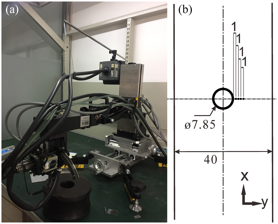
Residual stress measurement: (a) X-ray diffraction device and (b) measurement points (dimensions in mm).
Fatigue tests
The fatigue tests were conducted using a frequency of 12 Hz and stress ratio of 0.1 at room temperature. An MTS-100 KN-1 servo-hydraulic fatigue machine was used. To obtain the S-N data, the tests were conducted using three different load levels corresponding to net section maximum stresses of 155, 185, and 215 MPa, respectively. The tests were terminated when the specimen fractured or the fatigue life exceeded 106 cycles. Five specimens were tested under each set of conditions, and the average fatigue life was adopted.
Experiment results
Fatigue test results
The results of the fatigue tests are presented as semi-log S-N plots in Figure 5(a), from which it can be seen that all the fatigue-life enhancement techniques (chamfering, cold expansion, bolt clamping, and their combinations) used in this study produced positive results in the OH specimens. To compare the anti-fatigue effects of the different techniques, the fatigue lives of the corresponding specimens are shown in Figure 5(b)–(d).

(a) S-N data, (b) effect of cold expansion, (c) effect of chamfering, and (d) effect of bolt clamping.
From Figure 5(b), it is obvious that the fatigue life of the CE3.2 specimens is longer than that of the OH specimens, implying that the application of cold expansion improves the fatigue performance of the OH specimen. This is unsurprising considering that many previous studies have shown that cold expansion introduces a compressive residual stress around the edge of a hole, resulting in increased fatigue life. 16 Moreover, compared to the C1-BC6.4 specimens, the fatigue life of the C1-CE3.2-BC6.4 specimens is longer. This shows that cold expansion also increases the fatigue life of the C–BC specimen.
The effect of chamfering is shown in Figure 5(c), from which the fatigue lives of the C0.5-CE3.2 and C1-CE3.2 specimens can be observed to be longer than that of the CE3.2 specimens, particularly under higher loads of 155 and 185 MPa. This indicates that chamfering is also beneficial for fatigue-life improvement. Furthermore, with the length of the chamfer increasing, the fatigue life of C-CE specimen increases.
With regard to the comparative effects of cold expansion and bolt clamping on the C specimens, the fatigue life of C1-CE3.2 was observed to be longer than that of C1-BC6.4 (see Figure 3(d)). In other words, cold expansion had a stronger anti-fatigue effect on the C specimens compared to bolt clamping.
Regarding the attempt to further improve the fatigue life of OH specimens by applying a combination of chamfering, cold expansion, and bolt clamping (specimens C-CE3.2-BC6.4), Figure 3(a) and (d) reveals that the procedure produced a longer fatigue life compared to all the other specimens. This observation can be related to the additional compressive pre-stress that bolt clamping adds to residual stress generated by cold expansion around the edge of the hole. It should also be noted that the application of a larger remote load produces a greater anti-fatigue effect, as indicated by the more dispersed data for lower stress levels.
The overall fatigue test results indicate that a combination of chamfering, cold expansion, and bolt clamping produces the best anti-fatigue effect, affording a 15.5-fold fatigue-life improvement compared to the OH specimens. The order of the test fatigue lives of the different specimens is given in Table 2.
SEM examination of fractured sections
The torque used for the bolt-clamping process has both positive and negative effects. 17 Usually, a large bolt torque induces a fretting fatigue failure mode, which has a negative anti-fatigue effect. 12 A bolt torque of 6.4 N m was thus applied to the chamfered plates in this study, with no significant wear or fretting observed on the surface of the BC specimens in the contact area of the washer (see Figure 6). In addition, all the fatigue-tested specimens broke within the minimum cross-sectional area.
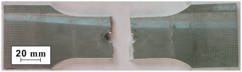
Fracture of the chamfered-cold-expanded-bolt-clamped specimens.
To further analyze the effects of the different fatigue-life enhancement techniques on the crack initiation location, the fracture surfaces of the specimens fatigue-tested under a load of 185 MPa were examined by SEM (see Figure 7(a)–(f)).
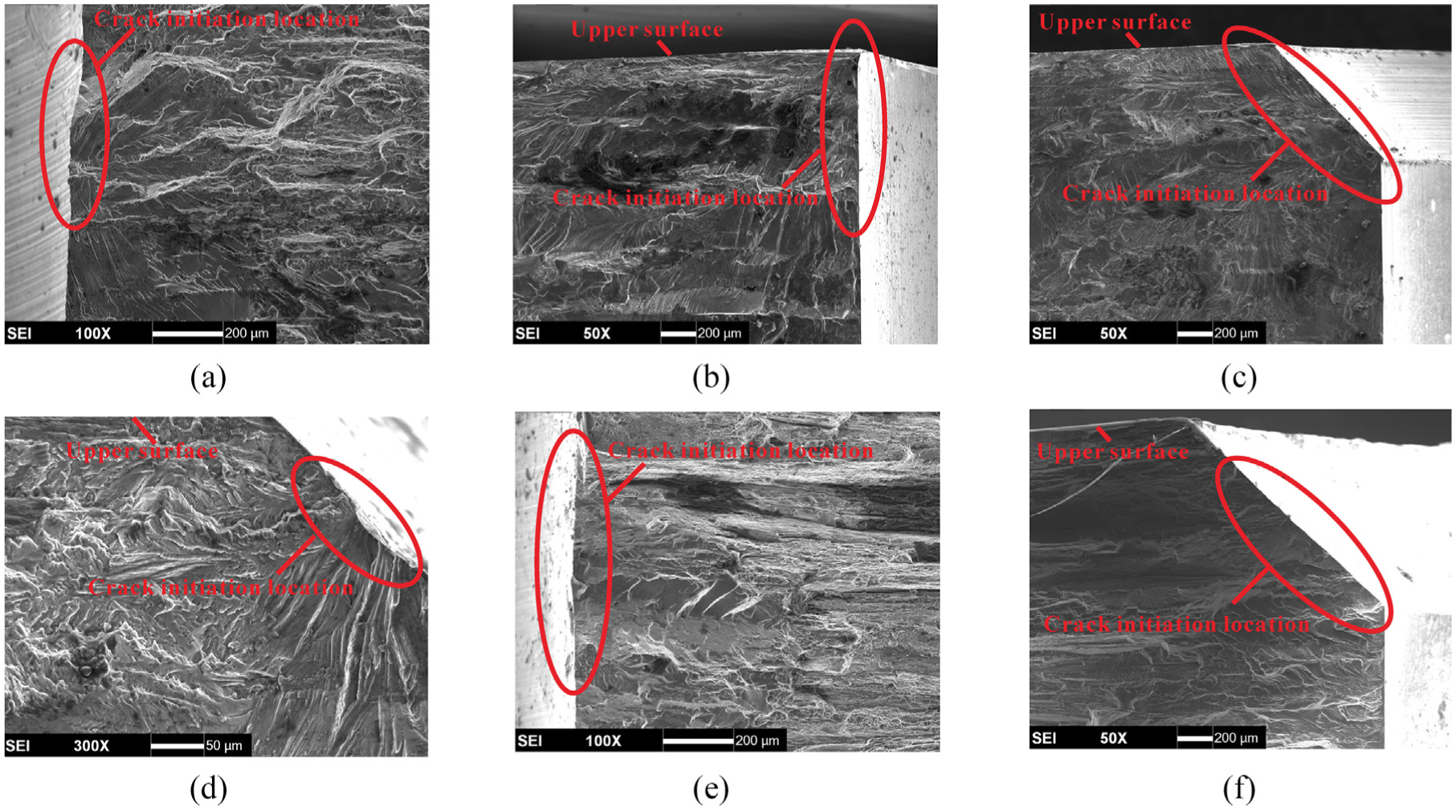
SEM images of the fracture surfaces of the test specimens: (a) OH, (b) CE3.2, (c) C0.5-CE3.2, (d) C1-CE3.2, (e) C1-BC6.4, and (f) C1-CE3.2-BC6.4.
In the OH and C1-BC6.4 specimens, the fatigue cracks were initiated on the middle plane, as shown in Figure 4(a) and (e). However, in the CE3.2, C0.5-CE3.2, C1-CE3.2, and C1-CE3.2-BC6.4 specimens, the fatigue cracks were generally initiated on the chamfer or the upper surface hole edge (Figure 7(b), (c), (d) and (f)). In other words, the application of cold expansion moved the crack initiation point from the middle plane to the chamfer or upper surface hole edge. Cold expansion thus had a greater effect on the crack initiation location than chamfering and bolt clamping.
Numerical analyses
FE model
The structural fatigue behavior was determined by the residual stress or pre-stress generated by the fatigue-life enhancement technique. To investigate the complex stress states around the hole edge in the fatigue-tested specimens, ABAQUS 6.13 was used to establish three-dimensional FE models of the specimens. The models were used to simulate the processes of fatigue-life enhancement. Because the specimen geometry and applied load were symmetric about the x–z and y–z planes, only 1/4 models of the specimens were used, to improve the calculation efficiency. A symmetrical boundary condition was thus applied to the symmetrical area.
Three-dimensional eight-node reduced-integration elements (C3D8R) were used to mesh the models. The minimum size of the hole edge mesh after refinement and convergence verification was 0.06 mm. The ABAQUS surface-to-surface algorithm, which enables pressure transfer between contacting surfaces and prevents the contact areas from penetrating each other, was used to define the contact surfaces. The friction coefficient between the mandrel and the original drilled hole during the cold expansion process was considered 0.13,9 (also equal to what is declared by the manufacturer of the lubricant used in the cold expansion process), while that between the washer and the plate was set to 0.288 and that between the bolt and the drilled hole was set to 0.16. 13
A multilinear hardening rule was used to simulate the mechanical behavior of the 2297-T87 Al–Li alloy. The stress–strain behavior of the alloy was determined by a simple tensile test (see Figure 2). The used mandrel and bolt were made from steel and therefore defined as linear elastic materials with Young’s modulus of 210 GPa and Poisson’s ratio of 0.3.
The simulation process for the C-CE-BC specimen involved three steps, as described in Figure 8. In the first step, the cold expansion process was simulated by pulling an oversized mandrel through the chamfered hole in the plate along the z-axis through incremental displacement on the lower face of the mandrel (Figure 8(a)). To consider the effect of the support ring, the mesh in the area between circles of radii 6 and 12 mm centered around the hole on the exit plane of the plate was constrained in the z-direction. The bolt-clamping process was simulated in the second step, wherein the cold-expanded plate and bolt were assembled (Figure 8(b)). For simplicity, the washers and bolts were modeled together. The bolt load algorithm in ABAQUS was used to apply the bolt-clamping force. The relationship between the bolt-clamping force and bolt torque is as follows 18
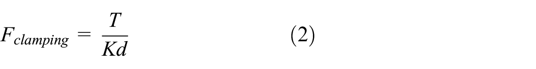
where

Simulation of the chamfered–cold-expanded–bolt-clamped specimen: (a) cold expansion, (b) bolt clamping, and (c) fatigue testing.
In the simulation of the CE or C-CE specimens, only the first and third steps were implemented, while the simulation of the C-BC specimens involved only the second and third steps.
Fatigue-life prediction using SWT method
Fatigue-life prediction can be used to quantitatively assess the anti-fatigue effect of a fatigue-life enhancement technique and be used for subsequent parameter optimization studies. The SWT method is a critical plane fatigue-life prediction method and is suitable for multi-axial stress state problems. 19 The fatigue-life prediction equation of the SWT method is as follows 20

where σn,max and Δεa are, respectively, the maximum normal stress and normal strain range,
Numerical results
Comparison of measured and predicted residual stresses
The circumferential residual stresses in the longitudinal direction (x-direction) of a CE3.2 specimen were measured and compared with those predicted by the FE method (FEM), as shown in Figure 9. Good agreement can be observed between the two.
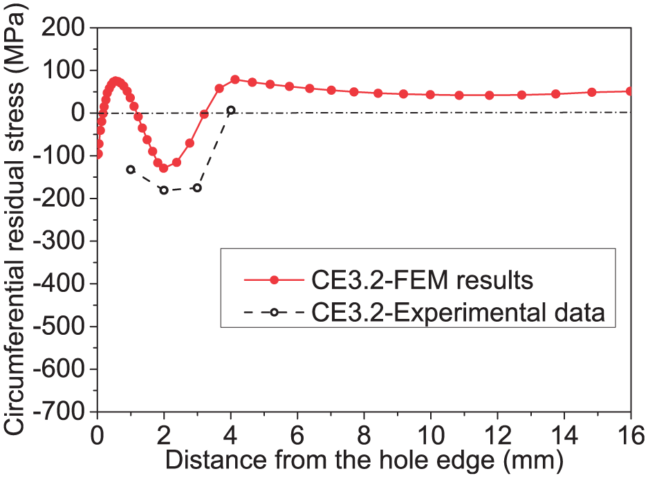
Comparison of measured and FEM-predicted residual stresses.
Evaluation of residual stress distribution
To compare the residual stresses induced by the different fatigue-life enhancement techniques, the distributions of the circumferential residual stresses (in the x-direction) of the respective specimens were obtained on the entrance plane, middle plane, exit plane, and across the thickness at the net section of the plate (see illustration in Figure 10). The results are presented in Figure 11.

Illustration of typical planes and thickness of open-hole plate specimens: (a) specimens with chamfered hole and (b) specimens without chamfering.

Distributions of the circumferential and residual stresses on the: (a) entrance plane, (b) middle plane, (c) exit plane, and (d) thickness.
Cold expansion generally generates a compressive circumferential residual stress around the hole edge, and the stress distribution is nonuniform along the plate thickness owing to the material flow and low boundary condition on the entrance and exit planes.17,21 However, the circumferential residual stress distributions on the middle plane (see Figure 11(b)) of all the CE specimens (C, non-C, BC, and non-BC) are similar. This indicates that the residual stress distribution in the middle region of the hole edge is mainly determined by cold expansion rather than chamfering or bolt clamping. The effects of chamfering and bolt clamping on the residual stress distribution in the vicinity of the hole edge are more notable on the entrance and exit planes than on the middle plane (see Figure 11(a), (c) and (d)).
To examine the effect of the chamfering on the residual stress, the distributions of the circumferential residual stresses on the entrance plane of the CE3.2, C0.5-CE3.2, and C1-CE3.2 specimens are shown in Figure 11(a). The maximum compressive residual stress of a C specimen can be observed to be greater than that of a non-C specimen. This implies that chamfering enhances the effect of subsequent cold expansion. In addition, the circumferential residual stress around the hole edge increases with increasing chamfering length, explainable by the experimental fatigue test results that show that a specimen with a larger chamfering exhibits a longer fatigue life.
Comparison of the residual stress distributions along the thickness of the OH and C1-BC6.4 specimens in Figure 11(d) clearly reveals that the compressive pre-stress induced by the clamping force occurs only near the hole edge on the upper and bottom surfaces. The bolt applies its load through the contact area between the washer and the specimen. The bolt-clamping force thus mainly affects the stress state of the upper and bottom surfaces, rather than that of the middle plane. In addition, the C1-CE3.2 and C1-CE3.2-BC6.4 specimens have similar residual stress distributions along the thickness, with the exception that the circumferential residual stresses around the hole edge on the upper and bottom surfaces of the latter are higher (see Figure 11(d)). This indicates that bolt clamping affects the residual stress induced by cold expansion.
Furthermore, after cold expansion, the upper and bottom surfaces of the hole in the C-CE specimen form a convex surface in the z-direction. Hence, during the application of the bolt-clamping force, there is a gap between the contact area of the washer and the CE specimen (see Figure 12(a) and (c)). There is, however, no such gap in a non-CE specimen (see Figure 12(b) and (d)). The resultant smaller contact area in a C1-CE3.2-BC6.4 specimen causes the magnitude of the circumferential stress around the hole edge to be much higher than that in a C1-BC6.4 specimen (see Figure 11(d)).
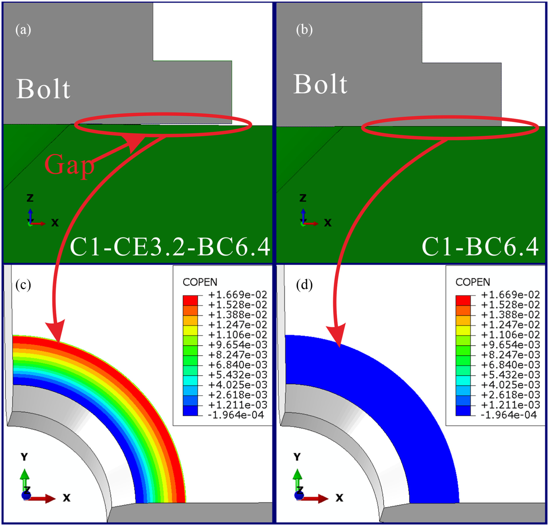
Illustration of the contact gap in (a) C1-CE3.2-BC6.4 and (b) C1-BC6.4 specimen; magnitude of the gap in (c) C1-CE3.2-BC6.4 and (d) C1-BC6.4 specimen (unit: mm).
FEM-determined longitudinal stress response
The mean stress, amplitude stress, and their distribution on the net cross section of the specimens on entrance, middle, and exit planes for a typically chosen value of the peak longitudinal load (185 MPa) are shown in Figure 13.
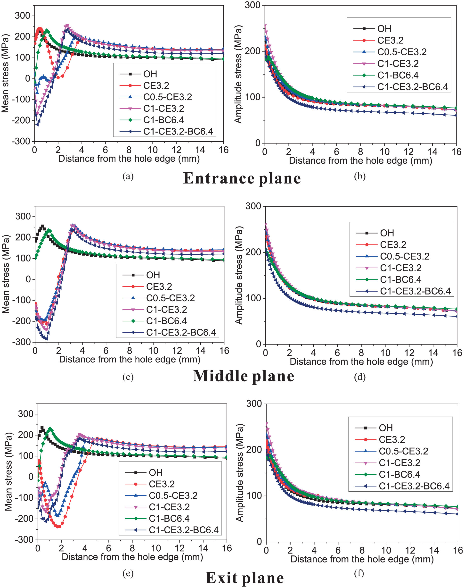
Mean stress and amplitude stress distribution on the net cross section of the specimens on the entrance, middle, and exit planes.
The mean stresses of all the fatigue-life-enhanced specimens near the hole edge on the entrance, middle, and exit planes are lower than those of the OH specimen (Figure 13(a), (c) and (e)), while the distributions of the amplitude stresses of all the specimens are similar (Figure 13(b), (d) and (f)). For the C-CE specimens, the mean stress near the hole edge on the entrance decreases with the increase in chamfering size, which is consistent with literature. 14 Furthermore, the mean stresses of the CE and C-CE specimens near the hole edge on the entrance plane are higher compared to the middle plane and exit plane. Therefore, initial fatigue cracks are more likely to be generated near the hole edge on the entrance plane.
The comparison of C1-CE3.2 and C1-CE3.2-BC6.4 indicates that the mean stresses of the hole edge decrease by applying a clamping force (Figure 13(a), (c) and (e)), which is in agreement with literature. 9 Moreover, the mean stresses and amplitude stresses of C1-CE3.2-BC6.4 on the hole edge are lower than those of other fatigue-life-enhanced specimens, indicating that C1-CE3.2-BC6.4 has the longest fatigue life (Figure 13), which agrees with the experimental results.
To further investigate the stress response, the longitudinal stress responses at three key nodes were considered. Here, node A is the node at which the mandrel first contacts the hole edge in a C specimen, while node B is the vertex of the chamfer and node C is the middle. In a non-C specimen, nodes A, B, and C coincide. The locations of these nodes are illustrated in Figure 14.

Nodes A, B and C in: (a) specimen with chamfering and (b) specimen without chamfering.
Figure 15(a)–(c), respectively, shows the longitudinal stress,
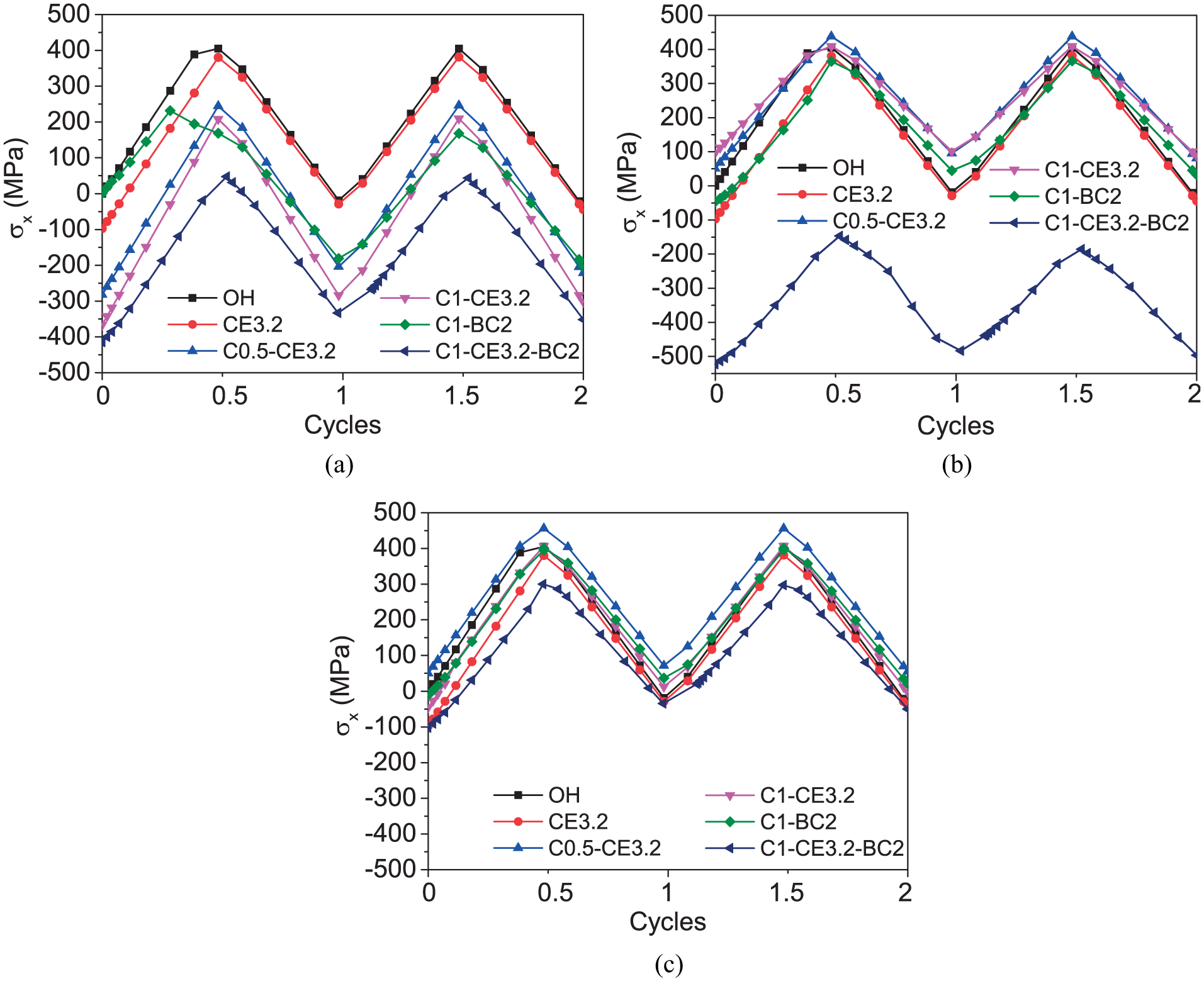
Histories of the longitudinal stresses at three nodes in different specimens subjected to a maximum cyclic load of 185 MPa.
As can be observed from Figure 15(b), there is no decrease in the maximum stress at node B of the C-CE specimens (C0.5-CE3.2 and C1-CE3.2). This indicates that chamfering has little effect on the fatigue life of the upper surface of the specimens. However, in the case of a C-CE-BC specimen (C1-CE3.2-BC6.4), the maximum stress at node B is significantly decreased. This is related to the fact that the circumferential residual stress at node B in a C1-CE3.2-BC6.4 specimen is quite high, owing to the effects of the convex shape of the edge in the z-direction and the bolt-clamping force.
As shown in Figure 15(c), for the C-CE specimens and C-CE-BC specimen (C0.5-CE3.2, C1-CE3.2, and C1-CE3.2-BC2), the stress level at node C is higher compared to node A and node B, indicating that the initial fatigue crack point is near node C. Moreover, the stress level at node C of the C-CE-BC specimen (C1-CE3.2-BC6.4) is lower than other specimens.
Based on the above analysis of the mean stresses, amplitude stresses, and longitudinal stresses at the three considered key nodes, it is reasonable to conclude that the specimens with combined chamfering, cold expansion, and bolt clamping (C1-CE3.2-BC6.4) have the longest fatigue life.
Fatigue-life prediction results
Figure 16 shows plots of the fatigue lives of the different specimens predicted by the SWT method against the experimentally measured fatigue lives for maximum cross-sectional remote loads of 155, 185, and 215 MPa. As can be observed from Figure 16, the SWT method underestimates the fatigue life, although the estimates are close to the 10-time error band. This is because the SWT method is mainly based on the fatigue crack initiation stage and does not consider the fatigue crack propagation stage.

Predicted fatigue life versus experimentally measured fatigue life.
To describe the deviation between the SWT-predicted and experimentally measured fatigue lives, an error index (ER) is defined as follows 22


The average absolute errors of the SWT method with respect to the fatigue-life enhancement technique are presented in Table 3. All the ER% values can be observed to be less than 120 and are also in agreement with previously published values. 23 This indicates satisfactory accuracy of the SWT method and its applicability to parameter optimization for the different fatigue-life enhancement techniques.
Average absolute errors of the SWT fatigue-life prediction method (ER%).

SWT: Smith–Watson–Topper; ER: error index.
Conclusion
We experimentally and numerically investigated the enhancement effects of chamfering, cold expansion, bolt clamping, and their combinations on the fatigue life of a 2297-T87 Al–Li alloy single plate. The best fatigue-life improvement was achieved using a combination of 1-mm chamfering, 3.2% cold expansion, and a 6.4-N m bolt-clamping torque, which increased the fatigue life by a factor of 15.5 compared to a pristine specimen under a remote load of 215 MPa.
Furthermore, the SEM results showed that the initial fatigue cracks in the specimens subjected to cold expansion mainly originated around the hole edge on the upper surface. FE analysis revealed that the addition of bolt clamping to the C-CE specimens further enhanced the compressive stress level near the hole edge, owing to the decreased contact area. The significant fatigue-life enhancement effect of the combination of chamfering, cold expansion, and bolt clamping can thus be explained by the considerable reduction in the maximum stress response, as also indicated by the fatigue test results. In addition, although the SWT method underestimates the specimen fatigue life, the accuracy satisfies engineering requirements.
Footnotes
Handling Editor: Michal Kuciej
Declaration of conflicting interests
The author(s) declared no potential conflicts of interest with respect to the research, authorship, and/or publication of this article.
Funding
The author(s) received no financial support for the research, authorship, and/or publication of this article.