
Abstract
To solve the visual servoing tasks in complex environment, a path planning method based on improved rapidly exploring random trees algorithm is proposed. First, the improved rapidly exploring random trees planning method is adopted, which keeps the observed feature points in the field of view. The start node and the desired node are initialized as roots of multi-trees which grow harmoniously to plan path of the robot. Then, the planned path is used to project the three-dimensional target feature points into the image space and obtain the feature trajectory for the image-based visual servoing controller. Finally, the feature trajectory is tracked by the image-based visual servoing controller. The proposed visual servoing design method takes field of view constraints, camera retreat problem, and obstacle avoidance into consideration, which can significantly improve the ability of the robotic manipulator, especially in the narrow space. Simulation and experiment on 6-degree-of-freedom robot are conducted. The results present the effectiveness of the proposed algorithm.
Keywords
Introduction
The visual servoing control system refers to a control system using visual feedback. The control goal is to adjust the task function
In IBVS, there may be infeasible camera motion for the image trajectory. Moreover, there is no direct control over the image/camera/robot trajectories induced by the servoing loop in the image and in the physical space. Therefore, these trajectories might violate the image or physical constraints. Such approaches are ineffective in complex visual servoing tasks. Chaumette 5 summarized the potential problems of IBVS method. Singularities in the image Jacobian matrix and local minima resulting from large displacements in the depth direction may cause instability and non-convergence. In Nadi and Derhami, 6 artificial neural networks were used to estimate inverse Jacobian matrix. For the traditional IBVS system, due to the lack of depth information, the camera sometimes performs an unnecessary translation along the z-axis away from the target and back again. The resulting motion is not time optimal and can require large and unachievable camera motions, which may cause the visual task failure. This phenomenon is termed camera retreat. The spherical model can not only avoid the camera retreat problem 7 but also facilitate the design of translation and rotation decoupling error vector.8–12 To solve this issue and recognize the features, some system can use the depth-sensing technology combining depth and color information for foreground segmentation based on an advanced color-based algorithm. 13 Relevant literature on partitioning and switching strategies shows that only a small fraction of the above constraints can be incorporated. 14 Wang et al. 15 presented a quasi-min–max model predictive control-based IBVS controller with tensor-product (TP) model transformation method. The control signals can be solved through numerical method, which avoid the singularities of the image Jacobian matrix and hence can solve the constraint problems for the classical IBVS controller. However, the existence of obstruction and other obstacles’ avoidance problem were not considered.
The path planning can program a feasible image feature trajectory between the initial and desired positions of the robot and guide it to move along the trajectory. In order to solve the above-mentioned problems of IBVS comprehensively and also for complex scenes with obstacles, it is a very effective method to incorporate global and general path planning into the control loop. The optimization of path planning in the robotic field has been widely studied and applied in visual servoing tasks, where the optimization indicators include the distance from the image boundary, the robot path length, and energy consumption. However, the IBVS principle is to continuously reduce the error of the current image and the desired image. The position obtained by path planning may not be consistent with the motion range of the camera, exceeding the joint limits of the robot or colliding with the obstacles. One of the ideas is to parameterize the trajectory and convert it into an optimization problem. The commonly used trajectory description methods are polynomials, 16 Rodriguez formulas, 17 and so on. The optimization objectives include the length of the trajectory, the curvature, and so on. The constraints include the field of view (FOV) constraints, robot joint angle limitations, and so on. 18 When there is an error in the calibration parameters of the camera, the trajectory of the actual execution is different from the planned trajectory, and the constraint may not be satisfied.
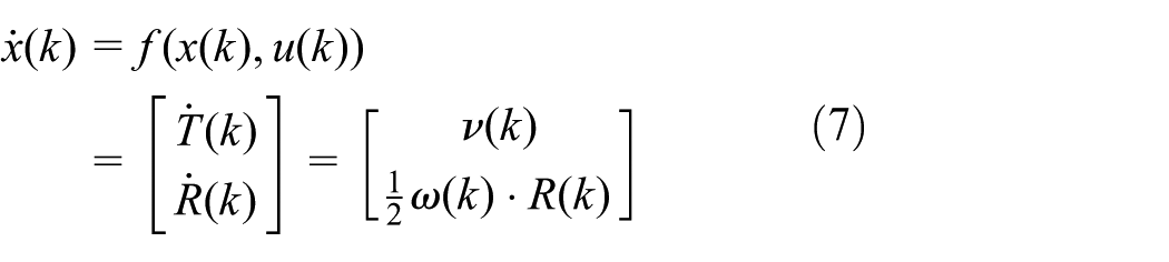
Another idea is to use the search method to optimize. Based on prior knowledge, the boundary between the target visible region and the invisible area can be calculated, and then the search algorithm is used in the robot path planning to calculate a path that satisfies the constraint and project it into the image space. The commonly used methods are based on rapidly exploring random trees (RRT) 19 and probabilistic maps. 20 The RRT is a single-query (SQ) algorithm in Wang et al., 21 which is less practical than the multi-query (MQ) method and is suitable for dynamic environments. In order to solve the problem of the movement path of a manipulator in the road, Biyun et al. 22 proposed a modified double tree random tree. However, it also suffers from an excessive computational load in the narrow space. Yunfeng et al. 19 and Wang et al. 23 proposed a multi-RRT method. The experiments show that this method has a good effect on solving the path planning under narrow space. The problem with some end-effector constraints has not been addressed in previous works. Based on the IBVS, an improved multi-RRT is introduced into the control. Unlike the traditional RRT, when a collision occurs in the multi-RRT, a new extension tree is generated and the path is planned in a multi-tree coordinated manner which smooths the trajectories. The advantages of the proposed algorithm are that both the camera FOV and “camera retreat” 6 are considered in the path planning phase.
The article is organized as follows: in section “Preliminary concepts and system frame,” the preliminary concepts and system frame are explained. In section “Path planning algorithm for IBVS controller,” the multi-RRT algorithm is revealed. Section “Results” is dedicated to the simulation and experiment analysis of the results.
Preliminary concepts and system frame
Camera model
In computer vision, it is common to use the central perspective imaging model shown in Figure 1. The rays converge on the origin of the camera frame {C} and a non-inverted image is projected onto the image plane located at
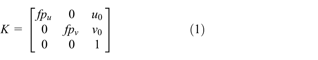

where

A perspective camera model.
Planning feasible camera trajectories
First, a feasible camera trajectory

where
The proposed planner explores the camera planning space for permissible trajectories by iteratively extending a search tree in this space. Simultaneously it tracks these trajectories in the robot configuration space.
As shown in Figure 2, both the image constraints and the camera work space are taken into consideration. A planning trajectory

System framework.
Path planning algorithm for IBVS controller
Compared with the traditional RRT algorithm, this article proposes a multi-RRT algorithm for visual servoing tasks. The planning trajectories can effectively guide the movements of the robot in the work space.
Basic principles of RRT algorithm
RRT is a fast search algorithm based on random sampling, which stores the collected random samples in a tree structure and continues to search for unknowns till the target is reached and the obstacles are known as a priori.21,26 As shown in Figure 3, the search tree is first generated from the initial point

RRT algorithm extension process.
In order to successfully implement the extension process, the path must be connected. Thus, path
Improved multi-RRT for camera path planning
The planned path will be served for the IBVS controller, as shown in Figure 2. Before the planning stage, the limit of the camera work space in Figure 4 (shown in point cloud) should be the input for the planning stage. The first three joints determine the position of the robot end. We choose step 20 for saving the memory resources.

Camera work space.
In the proposed algorithm (see Table 1), the exploring tree
Proposed new multi-RRT algorithm.

In order to improve the computational efficiency, a simple but effective strategy is implemented. If a point fails to be connected to existing tree, the new trees are created when collisions occur in environments exhibiting high obstacle densities or when regions are isolated by narrow passageways. If search spaces have zero or few obstacles, a lower number of trees will be created during the search.
In the case of planning in the camera configuration space, a random camera configuration is built by generating a uniform random camera position

where

Once a

where
Once the tree node with the nearest camera vector
where
Then the “CollisionCheck” function returns if a collision occurs between an edge and a set of obstacles. To judging whether the point of intersection inside the obstacle uses “SameSide” technology which is usually used for checking a point in a mesh (triangle). 29 However, here we do the same for a four-point planner which generates the obstacles in the environment.
In this search phase, each new point can be connected to the existing trees and there is no need for any additional trees. The trees are merged when a connection contains two or more trees, which controls the total amount of trees not exceeding the specified value. Finally, the returned
Tracking trajectories using IBVS
During the tracking process, the camera path (as edges of the camera tree) is determined as the camera FOV constraints, to ensure that the target features remain within the FOV and adjust to the planned path dynamically. For a 3D point with the image coordinates,
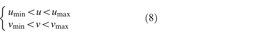
where umin, umax, vmin, and vmax denote the FOV constraints.
Suppose that

where
In IBVS controller, the feature trajectories

where

where

where

Note that in the path plan period, the desired feature trajectories are discrete. So at time

where
Results
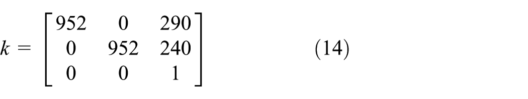
In order to verify the performance of the proposed method, the framework has been both implemented and simulated by a 6-degree-of-freedom (DOF) ABB IRB120 manipulator equipped with an eye-in-hand camera and a robotic toolbox for MATLAB, as shown in Figure 5. Four target feature points are selected as the coordinates of the center of four co-planar markers on the target object.

Simulation model and eye-in-hand system.
The intrinsic parameter of the camera is
The image feature constraint is
Simulation and analysis
First, an environment with obstacles is generated. The goal is located behind the gray wall (on the same side of the wall with the feature points) and small windows exist on the wall. The planned trajectory must pass the wall to connect the start and goal points. The coordinates of the points are [−0.45 +0.15 +0.60] and [+0.25 −0.20 +0.55] in the robot coordinate frame. The camera work space [xmin, xmax; ymin, ymax; zmin, zmax] is equal to [−0.35, 0.35; −0.35, 0.35; 0, 0.63]. For the sake of clarity, only the end position of the manipulator is shown on the screen. The link mechanism is ignored.
The process of the multi-RRT extension is shown in Figure 6. In Figure 6(a), two trees explore the environment. When the “CollisionCheck” is true, a new tree is added. Then, five trees are extended in Figure 6(b). Finally, the planned path is shown in Figure 6(c). Besides, a path planned by traditional RRT is depicted in Figure 6(c) as well. Compared to the traditional RRT, the result of proposed multi-RRT algorithm is smoother.

The multi-RRT extension: (a) two trees explore the environment, (b) five trees explore the environment, and (c) the final planned path.
As mentioned in section “Tracking trajectories using IBVS,” the simulation time and the planned path’s smoothness are related to
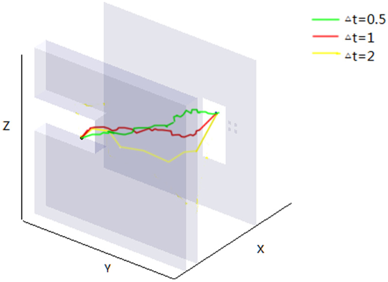
Planned path.
The initial pose of 6-DOF robot’s joint angle is from [−1.95 −0.24 0.05 −0.18 0.94 0.13] to desired [−1.58 0.15 −0.11 −0.53 1.07 1.35]. The results of feature points’ trajectories are shown in Figure 8, where the cross represents the initial position of the visual feature points and the circles are the desired features obtained at the goal position.

Image feature trajectories: (a) result of the traditional IBVS and (b) result of the multi-RRT.
Because
In the next section, experiments will be presented, which demonstrate the validity of the proposed scheme in image and camera work space constraints for the visual servoing task.
Experiments without obstacles
In the experiments, a square of 7 cm formed by four colored points is considered to be the target object. The initial joints of robot q0 = [−1.35, 0.56, −0.89, −0.52, 1.78, 0.12] in radians. The centers of each point are selected as the image features, and the initial and desired image features are as shown in Figure 9.

Initial and desired image features.
First, the traditional IBVS is implemented. As shown in Figure 10(a), camera retreat phenomenon causes the pose of joints 2 and 3 beyond their limits. Meanwhile, the image feature points are out of the FOV in Figure 10(b), and the visual servoing task is a failure.

Experimental results with traditional IBVS: (a) robot pose and (b) image plane.
Then the proposed multi-RRT-based algorithm is implemented as shown in Figure 11. As the figures demonstrate, the proposed multi-RRT algorithm ensures that the feature points are within the FOV. Compared with Figure 10(a), the pose in Figure 11(a) avoids the singular position.

Experimental results with the proposed algorithm: (a) robot pose and (b) image plane.
Experiments with obstacles
Some boxes are put in the manipulator work space which make the obstacles in the following experiment as shown in Figure 12, and in some regions the feature points are not visible in the FOV. The width of narrow channel is 0.21 m. The center of four target points is at [−0.1, −0.2, 0.3] in the robot-based coordinate frame. The initial pose of robot’s joints angle is q0 = [−1.30, 0.13, −0.46, −0.66, 1.76, 1.95], and the desired pose of robot’s joints angle is qd = [−1.69, 0.43, −0.45, −0.18, 1.34, 1.95].

Simulation environment and planned path using multi-RRT.
In the previous experiment, the traditional IBVS technique is first used to carry out the task of servoing. The traditional IBVS method results in the collision between manipulator and obstacles which also causes some parts of points out of view in Figure 13. Finally, the task was a failure.
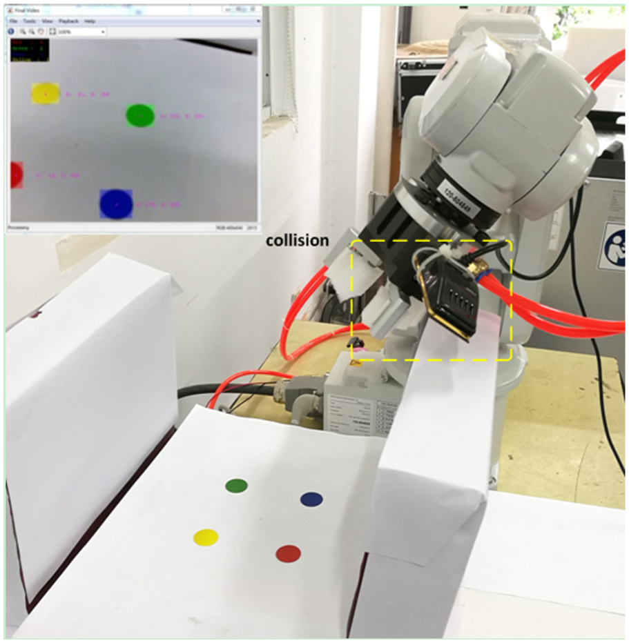
Experimental results by traditional IBVS.
However, the proposed multi-RRT-based algorithm can take these constraints into consideration. As shown in Figure 14, this approach keeps the feature points in the FOV and completes the task without collision as planned.

Experimental results with the proposed approach: (a) robot pose avoiding the obstacles and (b) image feature trajectories.
Conclusion
In this article, a new visual servoing design method based on improved multi-RRT algorithm is proposed, which can drive the manipulator from any given position within the working range to the position where the desired visual feature is located. The proposed improved multi-RRT method is introduced into the image visual servoing control which makes the trajectories smoother than traditional RRT algorithm, and the camera FOV is considered at the path planning phase. Compared with the traditional IBVS system, the approach proposed in this article can exhibit a better performance in the narrow space. In the future work, this method will be extended to an online IBVS controller for visual servoing containing joint limits’ avoidance and also experimental testing will be carried out.
Footnotes
Handling Editor: Zhaojie Ju
Declaration of conflicting interests
The author(s) declared no potential conflicts of interest with respect to the research, authorship, and/or publication of this article.
Funding
The author(s) disclosed receipt of the following financial support for the research, authorship, and/or publication of this article: This work was supported by the National Natural Science Foundation of China (nos. 61403122 and 51605137), Changzhou Sci&Tech Program (no. CJ20160013), and Fundamental Research Funds for the Central Universities (no. 2017B15114).