
Abstract
Composite structures with desire mechanical properties can be tailored to embed microstrip antenna in aerospace systems for reducing aerodynamic disturbance. The performance of a rectangular microstrip antenna in composite structures is analyzed in spectral domain in this work. Analysis shows that the electromagnetics of antenna in spectral domain is similar to the mechanics of composite structure in space domain. The electrical field, the immittance (impedance or admittance), and the current density are equivalent to the stress, strain, and stiffness in mechanics of composite structures. The governing equations, though may be of different dimensions, are also similar. It shall be expected that the performance of a microstrip antenna on composite structures is different from that on isotropic structures; just as the mechanics of the former is so different from that of the latter. Analysis confirms that antenna performance depends on the structure’s electromagnetic properties; similar to the mechanics of composite structures depends on the laminate layers’ ply angle and stacking sequence.
Introduction
The concept of microstrip antenna can be traced back half century ago, but it has not received considerable attention until the development of printed-circuit technology, photolithographic techniques, and low loss tangent substrates (a quantity related to dielectric damping.) Most studies on microstrip antennas were largely confined to antennas on isotropic structures using variation method1,2 or Green’s function. 3 A closed-form solution for the resonant frequency of a rectangular microstrip antenna was derived. 4 In recent development of smart structures, 5 embedded microstrip antenna has been proposed to protect it from environmental hazards. Full wave analyses of antenna performance in time domain, 6 in spectral domain, 7 and by approximation method 8 were applied to show that the resonant frequency is decreased by the overlay (when embedded) due to surface wave loss. 9 Similar investigations on microstrip antenna with dielectric overlay 10 and oxide overlay 11 also confirmed that the embedding can reduce antenna gain substantially. The above studies, however, were limited to antenna on isotropic structures. Many of the substrate materials, though treated as isotropic, are actually anisotropic. For example, sapphire, alumina, and fiber-reinforced laminated composites are anisotropic. Surface-attached microstrip antenna on anisotropic substrates12,13 and on uniaxial substrate14,15 were reported. The resonant frequency of a rectangular microstrip antenna embedded in uniaxial anisotropic substrates was analyzed using Hertzian vector potentials.16,17
Because of the lack of models to simulate microstrip antenna attached or embedded in structures (substrates), many previous studies thus assumed the structures to be isotropic. A woven Kevlar composite was considered isotropic in microstrip antenna design. 18 Similarly, isotropic assumption on composite structures was made to calculate the antenna gain. 19 A recent study showed that the performance of a microstrip antenna is strongly influenced by the dielectric constants of the substrate. 20 Electromagnetic co-design by modeling a microstrip antenna embedded in composite structures is necessary, and antenna performance may be improved when it is embedded in composite structures.21,22 This work aims at exploring the similarity between the mechanics of composite structure and the electromagnetics of antenna performance. The dependence of antenna performance on structure’s electromagnetic properties will be shown similar to the effect of dynamic response on composite structure’s mechanical properties.
Electromagnetic analysis
Composite structures composed of many continuous fiber/matrix layers have been widely used in aerospace systems to achieve desirable mechanical properties and facilitate sensor, actuator, and microstrip antenna integration.
5
An antenna compatible to microwave monolithic integrated circuits has the advantage of conformal to structural surfaces for enhancing aerodynamic performance. Consider a composite structure composed of N-layer as shown in Figure 1(a). Each layer is characterized by the permittivity matrix


(a) The configuration of an antenna and ground embedded in composite structure and (b) illustration of a microstrip antenna’s x-y-z axes relative to the composite structure’s 1-2-3 axes of ply angle
The subscript i will be deleted for now for simplicity.


where

Similarly, the Fourier transform of the air medium, denoted by the (N + 1)th layer, is


where

where the immittance (impedance or admittance) matrices
Similarity between mechanics and electromagnetics
Careful observations on equation (7) reveal that in addition to the coupling between structural mechanics and electromagnetics, the matrix form is similar to that that in mechanics of composite structures. The electromagnetics of microstrip antenna in spectral domain is similar to the mechanics of composite structure in space domain. The electric field
Similarity between mechanics of composite structure and electromagnetics of microstrip antenna.

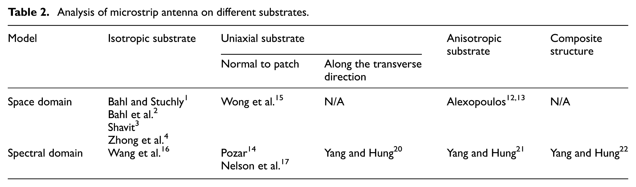
Analysis of microstrip antenna performance has come a long way as illustrated in Table 2. It has taken more than three decades of progress to understand the electromagnetics from isotropic substrates, to anisotropic substrates, and to composite-laminated structures. Numerical tools simulating microstrip antenna performance on composite structures, though no available as yet, may be realized in the near future by the similar path of finite element tools in simulating mechanics of composite structures. One may be able to analyze the performance of a microstrip antenna of any geometry embed in composite-laminated structures by finite element numerical simulation of structural mechanics. The data of mechanical stress and strain in structural mechanics can then be converted into electrical field and current density in electromagnetics of antenna.
Analysis of microstrip antenna on different substrates.
Antenna performance
The commonly seen composite structures in aerospace applications: symmetric balanced, symmetric cross-ply, anti-symmetric angle-ply, and asymmetric balanced composite-laminated substrates are studied in this work to show the spectral domain solution in analyzing the antenna electromagnetic properties. For a surface-attached antenna, if one assumed the structure to be isotropic, the antenna length and width are denoted by
It has been shown that one-mode expansion by the base functions


can achieve good accuracy,
20
where
Table 3 shows the size (
The size (performance) of a 2.4 GHz microstrip antenna when embedded in composite structures of d = 2.00 cm and

Table 3 also shows that the antenna size is dependent on composite structure’s stacking sequence. An antenna attached on [45/−45/45/45/−45/45] structure with
Antenna pattern
In addition to the frequency deviation and antenna size variations, the antenna pattern is even more sensitive to antenna position and composite structure’s electromagnetic properties. Without accurately accounting for composite structure’s electromagnetic properties in antenna design, the consequence is serious. Consider a 2.4 GHz microstrip antenna in [45/−45/45/45/−45/45] composite structures as shown in Figure 1(a). The antenna radiation efficiency is shown in Figure 2(a) and (b). If the antenna with size calculated by assuming isotropic structure were placed on composite structure, its gain will suffer more than −70 dB compared with that of correct size antenna. This result further confirms that antenna design by assuming composite structures as isotropic structures will be futile. In mechanics, one can have reliable structural design only when the material properties of the structure are accounted for.

The radiation pattern of a 2.40 GHz microstrip antenna embedded in [45/−45/45/45/−45/45] composite structures of (a)
Figures 3–5 show the radiation patterns of the same size of microstrip antenna placed on isotropic substrates and embedded in composite structures listed in Table 3. Figure 3(a) and (b) illustrates that the design failing to model the electromagnetics correctly in symmetric cross-ply [90/90/0/0/90/90] composite structures will suffer about −50 and −70 dB antenna gain in η = 0.50 and 0.75, respectively. It is obvious that a microstrip antenna embedded in composite laminates will have very different performances compared with that on isotropic substrates. The design of microstrip antenna on isotropic substrates cannot be directly applied to composite laminates, just as the structural design of isotropic materials and of composite materials are so different. Similar results in anti-symmetric angle-ply [45/−45/−45/45/45/−45] laminates of η = 0.50 and 0.75 are shown in Figure 4 with the antenna gain suffer about −50 and −70 dB, respectively. And in [30/45/60/−30/−45/−60] asymmetric composite structure, the antenna gain is about −50 and −60 dB in η = 0.50 and 0.75, respectively, in Figure 5. This radiation efficiency degradation is worsen in structures with higher anisotropic ratio. Only with the correct electromagnetic model in composite laminates, can the design of microstrip antennas become possible. But the above model in spectral domain is solvable only for rectangular microstrip antenna where the base function in equations (9a) and (9b) are available. For antenna in other geometries, numerical solution will be necessary. Such solution, though not available as yet, can be obtained by modeling the mechanics of composite structures and converting the stress/strain into electrical field and current density on antenna electromagnetics.

The radiation pattern of a 2.40 GHz microstrip antenna embedded in [90/90/0/0/90/90] composite structures of (a)

The radiation pattern of a 2.40 GHz microstrip antenna embedded in [45/−45/−45/45/45/−45] composite structures of (a)

The radiation pattern of a 2.40 GHz microstrip antenna embedded in [30/45/60/−30/−45/−60] composite structures of (a)
Conclusion
An electromagnetic model of microstrip antenna embedded in composite laminates has been established. Using Fourier transform, the homogeneous wave equations in spectral domain can be solved. The tangential electric field can be determined by the immittance equation, which is in similar matrix form as that in composite structure mechanics. Design of a microstrip antenna in composite laminates can be accomplished using a set of base functions, and the corresponding antenna patterns in space domain are also available using inverse Fourier transform. The model provides an efficient way to design and evaluate microstrip antennas in composite structures.
The characteristics of microstrip antennas embedded in composite structures are, in general, very different from those on isotropic substrates. Analyses show that antenna size and resonant frequency are so different from those when attached on isotropic structures. For composite structures commonly seen in aerospace systems, analyses validate that the antenna resonant frequency is a function of anisotropic ratio and stacking sequence. The difference between the mechanical properties in symmetric and asymmetric laminates is not “transferable” to their electromagnetic properties. The anisotropic ratio and stacking sequence of the composite laminates are critical to antenna performance, just as they are influential to structural mechanics. Without accurate modeling, the prediction of antenna performance in composite structures can be seriously flawed.
It takes more than three decades of progress to understand the electromagnetics from isotropic substrates, to anisotropic substrates, and to composite laminated structures. Numerical tools simulating microstrip antenna performance on composite structures, though no available as yet, may be realized in the near future by the similar path of finite element simulation on mechanics of composite structures. One may be able to analyze the performance of a microstrip antenna of any geometry embedded in composite laminated structures by numerical simulation of structural mechanics. The electric field on a laminate
Footnotes
Handling Editor: Byung Sun Kim
Declaration of conflicting interests
The author(s) declared no potential conflicts of interest with respect to the research, authorship, and/or publication of this article.
Funding
The author(s) disclosed receipt of the following financial support for the research, authorship, and/or publication of this article: This work was supported in part by the National Science Council, Taiwan, R.O.C. under NSC100-2221-E006-098-MY3.