
Abstract
This article reports an investigation of the influence of process parameters on the obtainable dimensional accuracy when drilling glass using abrasive jet machining. In particular, holes were drilled out of glass sheets, and the effects of standoff distance, nozzle diameter, particle grain size and applied pressure on the kerf taper were examined. An artificial neural network technique was used to establish a precise model of kerf taper as a function of the process parameters. The proposed model was then optimised, and the conditions to minimise the kerf taper were identified using a genetic algorithm. The results revealed that standoff distance has a major effect on kerf taper, and it proved possible to substantially reduce the kerf taper by applying an axial feed to the nozzle so that the standoff distance is kept constant during the machining process.
Keywords
Introduction
In abrasive jet machining (AJM), material removal takes place due to the action of a focused stream of abrasive particles ejected from a nozzle by highly pressurised air and accelerated towards the workpiece.1–3 AJM has recently shown a significant potential to manufacture micro-devices, especially to produce precise channels and holes.2,3 However, in order to enable further advances of this technology, it is essential to have a known and reliable relationship between the input parameters and their desired output results, such as material removal rate and kerf taper, so that the optimum process parameters can be identified.4–11
The quality of surfaces generated by AJM has been discussed by many investigators seeking to estimate the effects of process parameters. Balasubramaniam et al.12–14 found the surface generated had a reverse bell-mouthed shape, with entry side diameter in the target material depending on the values of the process parameters. It was found that nozzle diameter and standoff distance (SoD, the distance between the nozzle exit and target surface of the workpiece as shown in Figure 1) were the most significant parameters in determining the shape of the machined surface.

Schematic representation of AJM.
Farimani 15 investigated the influence of AJM variables on kerf characteristics of the machined channels. It was found that increased air pressure increased the depth and width of the machined groove and decreased the kerf taper angle. Liao and Chen 16 studied holes drilled by AJM and found that AJM generates a kerf taper on machined holes, as measured by the difference between the upper and lower diameters of the holes. Srikanth and Rao 17 reported that decreasing SoD reduced the divergence of the hole produced and improved the dimensional accuracy. Arunkumar et al. 18 examined the effect of AJM process parameters on matters such as kerf taper angle and surface roughness. It was observed that the taper angle decreased with the increase in pressure. Reddy and Srikanth 19 found that the kerf taper reduced by keeping SoD constant and by increasing time of machining but that relationship between the time and kerf taper was not linear.
Fan and Wang 20 investigated how the kerf taper and profile of the hole diameter depended on the AJM processing parameters. It was found that both kerf taper and hole diameter increased significantly with the increase in SoD. It was also found that kerf taper decreased with the use of large nozzles and the reverse applied for small nozzles.
Ali and Wang 21 reported that using a circular cross-sectional jet nozzle resulted in tapering of the machined groove. This was explained by the larger number of particles impacted the surface near the centreline of the machining path than near its edge which resulted in excessive loss of kinetic energy close to the wall of the groove. This was due to abrasive particle deflections and inter-particle collisions during rebound. In order to avoid this effect, the authors recommended slightly tilting the nozzle during machining.
A number of modelling approaches have been developed for AJM with the aim of optimising the process. Some researchers22–27 applied Taguchi and analysis of variance (ANOVA) techniques to experiments designed to maximise material removal rate and minimise kerf taper.
Shriyan et al. 26 used the Taguchi method to design AJM experiments in order to study the kerf taper. The experimental work investigated SoD, air pressure and size of the abrasive grains as process parameters. The results were analysed using ANOVA and showed that as the pressure increased, there was a significant decrease in the kerf taper.
Jain et al. 11 optimised the process AJM parameters using a genetic algorithm (GA) to obtain the best possible machining performance. Samani et al. 28 used an artificial neural network (ANN) based on experimental results of drilling glass by AJM to develop models for the effects of input process parameters (air pressure, SoD and particle grain size) on material removal rate, overcut and kerf taper. The results showed that ANN models could be used to model the process outcomes as a function of the input process parameters and successfully predict the performance of the process. Abdel-Naby 5 used an ANN to interconnect cutting variables and cutting performance for abrasive water jet machining. Different network structures were evaluated for each individual performance (using single output). Also, a general network which contained data for all performances was constructed (using multiple outputs). It was concluded that using a single output gives more accurate results than multiple outputs.
Reviewing the literature, it was found that there have been no studies reported on the influence of AJM process conditions on the obtainable kerf taper, only attempted to optimise the performance of AJM. To help make good this omission, this investigation examines those factors in the AJM process which were most important in determining resulting kerf taper, with the intention of minimising it. A series of holes were drilled under different air pressures (Pr), nozzle diameters (dn), particle grain sizes (dg) and SoDs. The kerf taper of the holes produced was taken as the measure of the dimensional accuracy for this experiment. Then, a model of the kerf taper was produced using an ANN. The purpose of the ANN models developed here was to establish a correspondence between the input parameters and the kerf taper. The reason for using an ANN for the modelling is because of its ability to be trained using the empirical results of the experiments.5–7 This allows better optimisation of results. In this article, a GA was chosen to identify the optimum process variables for minimising the kerf taper.
The results obtained highlight the significance of SoD as the most effective parameter determining the kerf taper. Accordingly, axial feeding was investigated as a method of maintaining the SoD at the optimum value during the entire machining process.
Kerf taper of AJM machining process
The kerf taper is an undesirable feature of AJM machining process. It is a measure of the geometric distortion of the drilled hole. It is a dimensionless quantity, though usually expressed as millimetre per millimetre: the difference between inlet and outlet diameters of the drilled hole divided by the sheet thickness, see equation (1) 4 and Figure 2

where
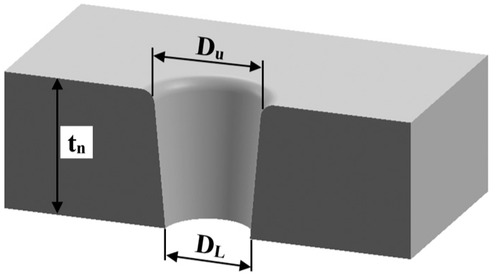
Typical cross section of hole generated by AJM process.
Experimental work
Experimental setup
Soda lime glass is an easy-to-manufacture, relatively cheap material which is widely used in industry, especially bottles and jars for beverage and food containers, lamp envelopes and windows in buildings. In this study, soda lime glass sheets, 3 mm thick, were drilled using AJM with sand as abrasive, owing to its ready availability and low cost. Table 1 presents the properties of workpiece and abrasive materials, soda lime glass and sand. 29
Properties of soda lime glass and sand. 27

The experimental procedure was to fix the glass sheet on the table of the computer numerical control (CNC) machine with the tool attached perpendicular to the specimen surface, as shown in Figure 3.

Fixture of the blasting gun against the specimen.
Two rubber tubes were connected to the blasting gun, one to carry sand from the sand reservoir, and the other connected directly to the air compressor (Figure 3). The blasting gun mixed the abrasive sand particles and air. This mixture was fired from the nozzle of the gun with a high stream velocity. An air compressor with a maximum pressure of 0.9 MPa was used to provide a range of applied pressures and make it possible to examine the effect of change in pressure on the machining process. The sand was dry and sieved. To obtain particles of different sizes, a sieve shaker was used.
Three brass nozzles were made especially for this project, with 4-, 5- and 6-mm inner diameters and with the same length (30 mm) of the final internal section of the nozzles, as shown in Figure 4.

Examples of nozzles used in the tests, 4, 5 and 6 mm; all dimensions are in millimetres.
Design of the experiments
The dimensional accuracy of the hole drilled through the glass sheets was obtained for different machining parameters. The system performance was investigated by varying one factor at a time; when changing one parameter, the remaining parameters were kept constant. The parameters that were varied in order to assess their effect were air pressure, nozzle diameter, SoD and abrasive grain size. Each factor had three values, as shown in Table 2.
AJM process parameters for drilling holes.

Three air pressures were used: 0.3 MPa (minimum), 0.6 MPa (medium) and 0.9 MPa (maximum). The SoDs were 4, 6 and 10 mm, as recommended in previous papers.12,22,23 The chosen average diameters of the sand particles were 150, 300 and 600 µm, because these were readily available, and recommended by Maros, 4 and proved to be well matched to the three nozzle diameters used.
Results and discussion
Effect of SoD
It is observed that AJM with soda lime glass, SoD has a major effect on kerf taper of the holes produced. The relationship between SoD and kerf taper for the 5-mm nozzle and different pressures is shown in Figure 5, and it is clear that for SoD > 6 mm, the kerf taper increased substantially. The higher values of SoD allow greater jet divergence before impingement and this increased material removed at the periphery relative to that along the centreline of the jet.

Effect of standoff distance on kerf taper at three air pressures for particle grain size 600 µm and nozzle diameter 5 mm.
Effect of pressure
It was noticed that increasing air pressure resulted in a reduction of the difference between top and bottom hole diameters which reduced the kerf taper (see Figure 5). That is because at higher pressure, the sand particles have higher kinetic energy and remove a larger volume of material along the axis of the hole, cutting a more cylindrically shaped hole, thus increasing the lower diameter and decreasing the value of (DU − DL). That is, the higher the pressure, the smaller the kerf taper. This effect persists as the SoD increases even for SoD > 6 mm.
Effect of nozzle diameter
Figure 6 shows the effects of nozzle diameter on kerf taper for three grain particles sizes for a SoD of 6 mm, and an air pressure of 0.9 MPa. It was observed that increasing nozzle diameter resulted in an initial reduction in the difference between top and bottom hole diameters which reduced the kerf taper. This decrease in kerf taper is because of the increase in flow rate of abrasive particles with larger dn, a higher number of particles exit from the nozzle with greater velocity which results in a larger volume of material being removed, but preferentially from the centreline. Increasing nozzle diameter decreased the difference in rate of material removal between centreline and periphery and so decreased the difference between upper and lower diameters. This result is in agreement with what was reported in Balasubramaniam et al. 13 However, this phenomenon appears to dominate only up to 5 mm, for larger diameter nozzles the kerf taper slightly increased. This can be attributed to the reduction in kinetic energy of particles ejected by the larger diameter nozzle and reduction in peripheral velocities.

Effect of nozzle diameter on kerf taper for three different grain sizes, for SoD of 6 mm and air pressure of 0.9 MPa.
Effect of particle grain size
It was found that the difference between the upper and the lower hole diameters reduced with increase in particle grain size, thus the kerf taper also decreased (see Figure 6). Larger grain particles have higher kinetic energy with greater ability to penetrate into the workpiece surface. Also, for larger mass particles, greater concentration is expected at the centre of the stream than that at the periphery. Particles with lower mass will tend to concentrate less along the centreline of the jet, spread out more and so the kerf taper increases when using smaller particles, but the effect is non-linear. Changing from 150 to 300 µm has much less effect than changing from 300 to 600 µm.
Modelling with ANN
ANN was used to model the kerf taper as a function of the machining parameters based on obtained experiments results. It allows the prediction of kerf taper for different input variables. MATLAB was used to create a number of variations on a feed forward ANN, for example, different numbers of hidden layers. The input and output sets resulting from the drilling experiments were utilised as training input patterns. The best network was selected based on the minimum least mean squared error (MSE), as shown in Table 3.
MSE for different ANN model structures for kerf taper output.
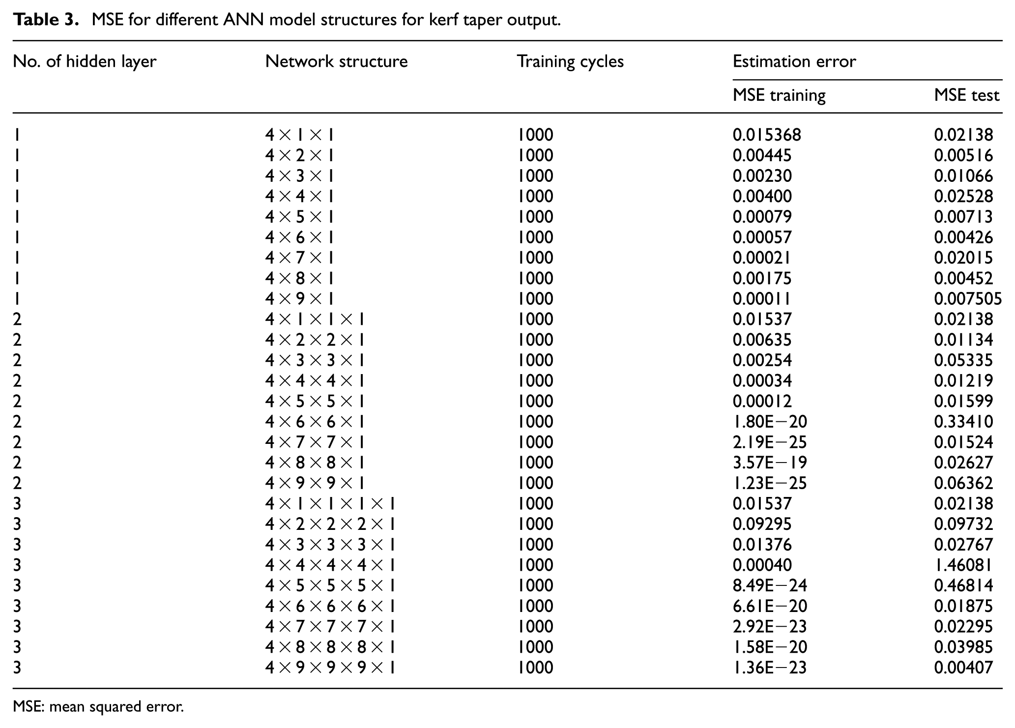
MSE: mean squared error.
It was found that the 4 × 9 × 9 × 9 × 1 structure network provided the best performance as it has the lowest value of MSE for the training examples. After the kerf taper networks were developed, a second performance test was used to test the estimation ability of the models. Based on the MSE of the testing examples, it was found that the 4 × 9 × 9 × 9 × 1 structure had the lowest MSE for the validation, see Table 3. This second test confirmed that the 4 × 9 × 9 × 9 × 1 was the best design to be used in the estimation of kerf taper. Figure 7 shows the optimum structure 4 × 9 × 9 × 9 × 1 with three hidden layers with nine neurons each, four input parameters and the kerf taper as an output. Figure 8 presents a comparison between the real kerf taper measurement and the estimated kerf taper by training. Figure 9 illustrates the difference between measured and estimated kerf taper.

The optimum structure 4 × 9 × 9 × 9 × 1.

Measured kerf taper versus estimated kerf taper by training.

Measured versus estimated kerf taper by testing.
Optimisation with GA
The network structures selected to quantify kerf taper by ANN were processed using a GA to identify the optimum process parameters that give minimum kerf taper. Figure 10 shows a flow chart for the GA.
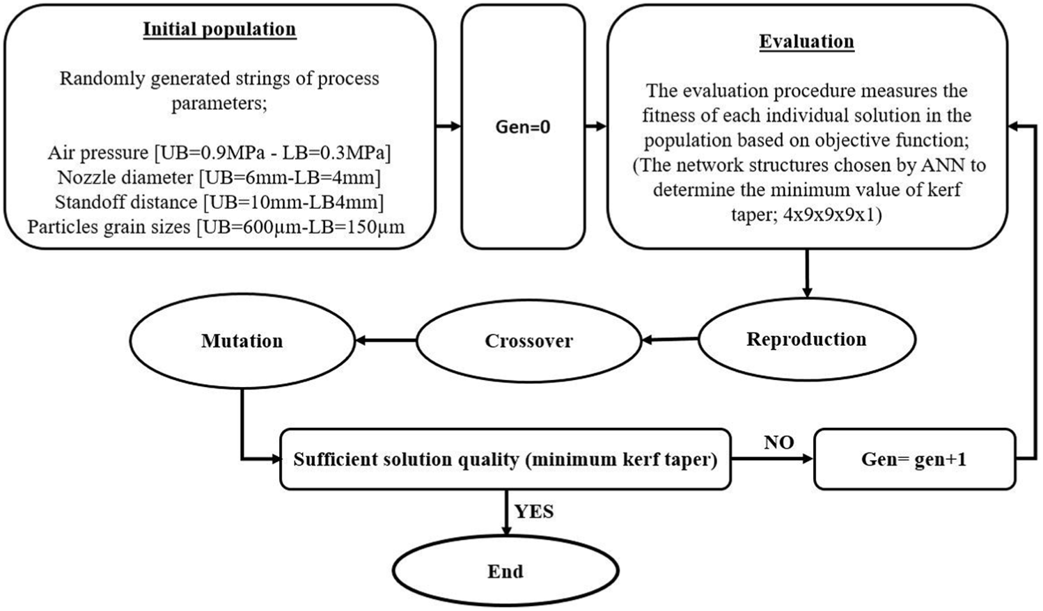
Procedure of genetic algorithm.
Experimentally, the optimum values of process parameters which gave minimum kerf taper were found to be pressure = 0.9 MPa, particles grain size = 600 µm, nozzle diameter = 5 mm and SoD = 4 mm. The kerf taper obtained using these parameters was 0.052 mm. However, when using the GA to optimise these parameters, the kerf taper obtained became very small compared with previous cases. This means that the efficiency of each parameter depended on the choice of the other parameters. Genetic optimisation could give the acceptable solution fast compared with the experimental work. Table 4 shows comparison between optimum values of kerf taper obtained from experimental work and GA optimisation. However, it is worth emphasising that the validation experiment was carried out for conditions set as close as possible to optimum values to test the GA and ANN models. There is a noticeable difference between the experimental results and those predicted using the GA. It should be noted that in the region of the global minimum, there are sharp changes in kerf taper predicted by the GA with small changes in the process conditions, so that the small difference between experimental dn (5.0 mm) and the optimum dn (5.3 mm) produces an order of magnitude difference between the kerf tapers. However, it must be remembered that the use of the GA is not to predict an exact value of the kerf taper but to identify the optimum parameters that gave minimum value of the kerf taper, as shown in Table 4.
The optimum values of process condition for minimum kerf taper versus the measured ones.
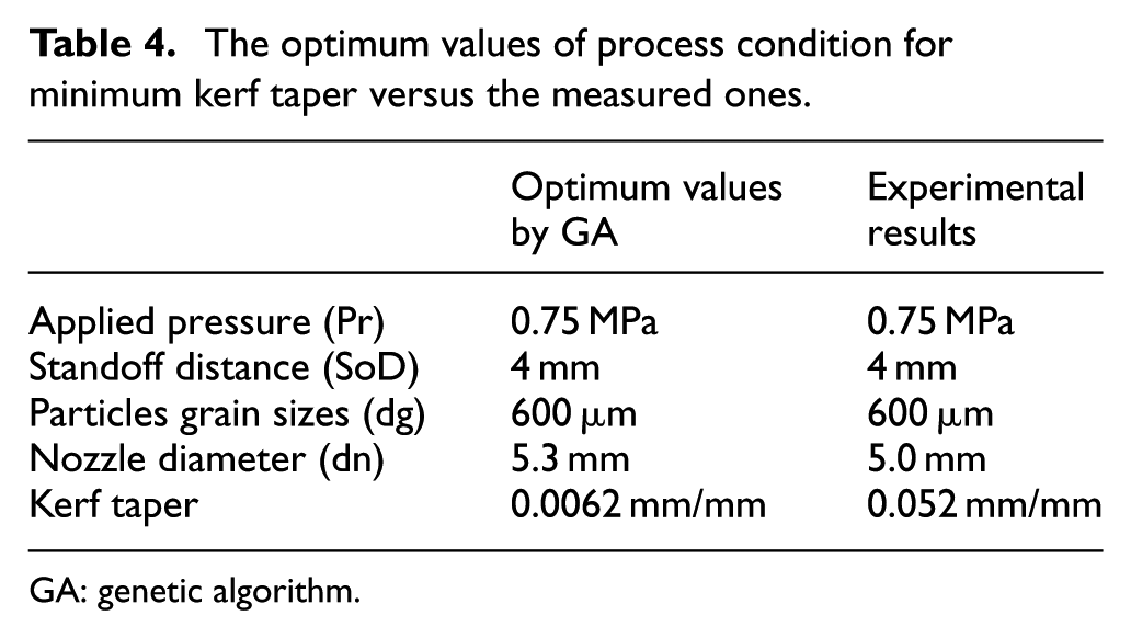
GA: genetic algorithm.
Applying axial feed
Because SoD is known to have a significant influence on the kerf taper, the second part of the experimental work was to develop an original technique to improve the accuracy of the generated holes by applying an axial feed to the nozzle to maintain constant SoD. The holes produced in this way were assessed to determine how effective the new technique was in improving their dimensional accuracy.
In the previous experiments, the nozzle was maintained in a fixed position during each drilling trial so, the effective SoD increased with cutting time, extending over the entire thickness to be cut, which would be expected to lead to poorer dimensional accuracy. A second set of experiments was carried out in which the nozzle was moved in the direction of the depth of cut at a rate equal to the rate at which the cutting was proceeding, this is termed ‘axial feeding’. The results from the two procedures were compared to assess the effect of axial feeding on the quality of the cutting process. The axial feed of the nozzle towards the target surface was applied over a distance of 3 mm, equivalent to the thickness of the glass sheet. Because the machining time was already known, the rate of axial feed could be immediately determined. Obviously, a different axial feed rate was used for each hole drilled, as machining time was different for each set of parameters used. Figure 11 illustrates the difference of drilling technique without feed and with feed.

Different hole drilling techniques: (a) drilling hole without axial feed and (b) drilling hole with axial feed.
Figure 12 illustrates the performance of the cutting process in terms of resulting kerf taper when drilling holes with and without axial feed. It was observed that the application of axial feed substantially reduced the kerf taper of the machined holes. When no axial feed was applied, the SoD distance varied with cutting time for the entire period of the cutting process, and the kerf taper increased because the jet diverged with increase in distance from the nozzle exit. However, with the application of axial feed the continuous matching of SoD to workpiece prevented increased jet expansion during cutting and reduced the difference between upper and lower hole diameters which, in turn, reduced the kerf taper. Figure 13 shows the difference between the shape of a hole generated by AJM with and without axial feed. The feed rate is expressed as
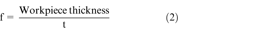
where t is the time taken for drilling a complete through hole according to the chosen parameters in each experiment. Note that the experiments presented in this section are aimed to demonstrate the feasibility of the proposed approach by giving samples for comparison between with and without applying axial feed.
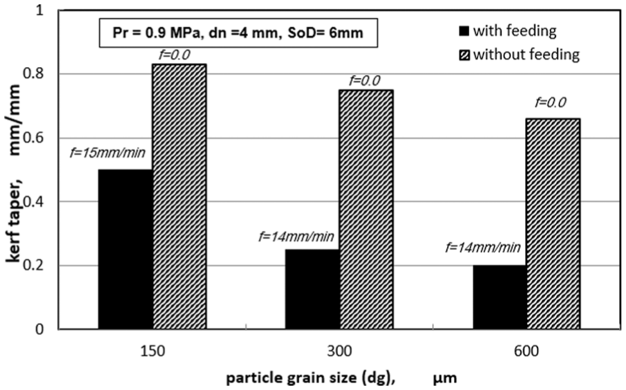
Comparison between kerf taper for holes drilled with and without axial feed for three particle grain sizes for dn = 4 mm, SoD = 6 mm and Pr = 0.9 MPa.
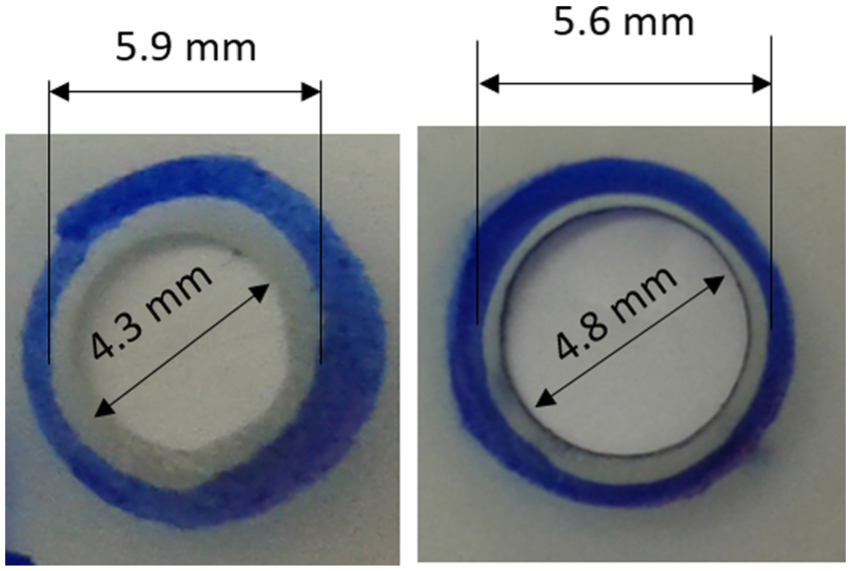
Comparison between holes generated with and without axial feed for SoD = 6 mm, with dn = 5 mm, dg = 600 µm and air pressure of 0.9 MPa (inner arrows show DL and outer show DU): (a) without feed kerf taper = 0.43 mm/mm and (b) with feed kerf taper = 0.27 mm/mm.
Figure 14 shows the effect of feed rate on kerf taper. It can be seen that the kerf taper varied almost linearly from 7 to 17 mm/min. As the axial feed rate increased so did the kerf taper. This was due to the increase in material removed in peripheral areas at the entrance to the hole combined with less material removed at the periphery of the hole at the bottom, with increase in machining time. Figure 15 shows the differences in shapes of hole generated by AJM for three feed rates and 4-mm-diameter nozzle.

Effect of feed rate on kerf taper without axial feed for 4-mm nozzle, SoD of 6 mm, air pressure 0.9 MPa and medium size sand grains.
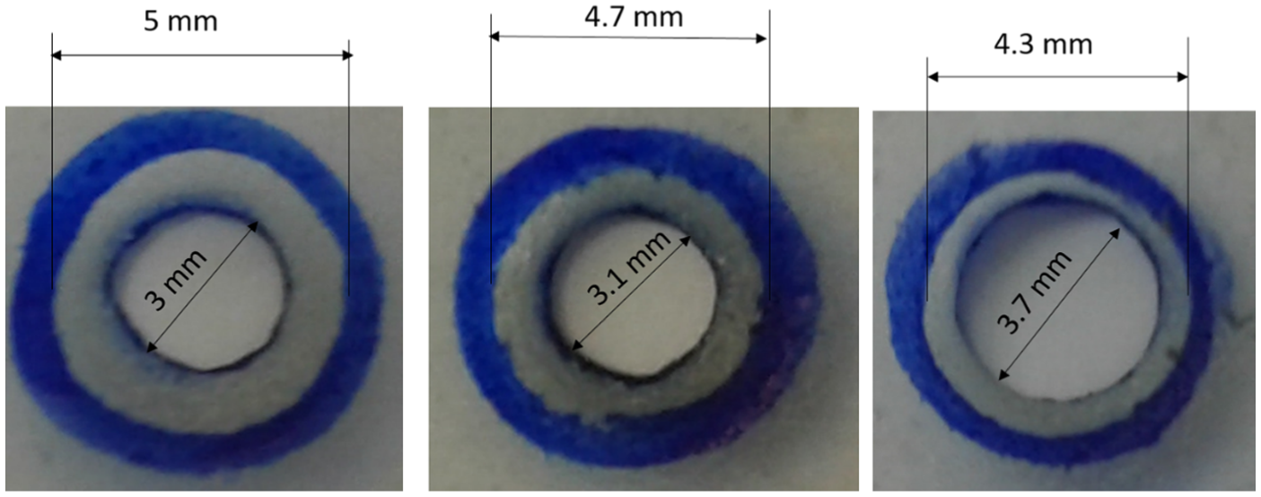
Holes generated at different axial feed rates with dn = 4 mm, dg = 300 µm, Pr = 0.9 MPa and SoD = 6 mm.
Conclusion
In this article, an experimental investigation focused on measuring generated kerf taper of holes in 3-mm-thick soda lime glass produced by AJM. The experimental results were utilised to develop an ANN predictive model of kerf taper as a function of the process parameters. Genetic optimisation was utilised to identify the optimum process parameters to give minimum value of kerf taper based on the ANN model. A study carried out on applying axial feed to the machining process demonstrated its ability to improve dimensional accuracy.
Specific conclusions drawn based on the results obtained for the range of parameters investigated are as follows:
SoD makes an important contribution to the magnitude of the kerf taper generated when drilling holes using AJM. The kerf taper increased monotonically with SoD, and for SoD > 6 mm, there was significant reduction in dimensional accuracy.
Nozzle diameter also has a substantial effect on kerf taper. It was found that kerf taper had a minimum value between 5 < dn < 6 mm, but with the increase in nozzle diameter, there was a steady increase in kerf taper.
Increasing abrasive grain size reduced the kerf taper, but this is a highly non-linear effect being much more significant at smaller grain sizes than larger.
Higher air pressure in the nozzle gave smaller values for the kerf taper, but the effect is more pronounced at higher values of SoD.
The ANN offered a reliable means to model the AJM process and accurately estimate output values for various values of the process parameters. The 4 × 9 × 9 × 9 × 1 network structure worked best and enabled accurate estimation of the kerf taper.
The GA enabled an optimum solution for minimum kerf taper to be identified quickly and accurately predicted optimal process parameters associated with minimum kerf taper.
Optimisation showed that the machining parameters are inter-related, and any one must match the others, in particular, the pressure must be compatible with SoD, and the size of the abrasive particles must be consistent with nozzle diameter.
It has been demonstrated that it is possible to greatly reduce the kerf taper by applying a pre-calculated axial feed motion to the nozzle during the drilling process.
Footnotes
Handling Editor: Chenguang Yang
Declaration of conflicting interests
The author(s) declared no potential conflicts of interest with respect to the research, authorship, and/or publication of this article.
Funding
The author(s) received no financial support for the research, authorship, and/or publication of this article.