
Abstract
Rescue robots can replace rescue workers in search and rescue missions in unknown environments and hence play an important role in disaster relief. To realize the advantages of high carrying capacity, easy control, and simple structure to adapt to a complex disaster scene, a novel wheel-legged rescue robot, integrated with rescue function modules, was designed for the present work. Three motion states were analyzed in detail. Mechanical properties were studied to provide basis for parameter optimization. The performance indices, which include mechanical properties, motion amplitudes and movement stability, were proposed, and the structural parameters were further analyzed and optimized based on these performance indices to make the overall performance of the robot achieve the best. Results show that the motion state of the wheel-legged rescue robot can perform real-time transformations and hence can be used in complex environments.
Introduction
Frequent natural disasters around the world have brought huge casualties and property loss to people. However, rescue tools are mostly semi-autonomous, which cannot meet the needs of the rescue. A post-disaster environment also poses danger to rescue workers.
A rescue robot is a type of mobile robot that can be used to complete search-and-rescue missions during natural disasters, accidents, and other emergency situations. They not only avoid or reduce casualties, but also improve the efficiency of the rescue. The important role rescue robots play in disaster missions has earned significant interest in the field of robotics in recent years.1–3
Among the existing rescue robots, tracked rescue and wheeled rescue are common motion modes. 4 The above two motion modes have high efficiency and high load carrying capacity. Therefore, they have broad application prospects.5–11 However, the tracked and wheeled robots cannot easily cross obstacles. In order to adapt to the complex environment, the multi-legged robots have been developed.12,13 However, the speed of the multi-legged robots is slow and it has complex structures. Besides, R Haraguchi et al. 14 and Neumann et al. 15 designed the snake-like robots by imitate snake movements, and thus can move on complex terrains. Because of their many joints and degrees of freedom (DOF), this type of robot cannot be easily modeled or controlled.16,17
In order to improve the complex environment adaptability of robot, many scholars combine different motion modes so that robots can convert motion states according to different terrain. For example, Huang et al. 18 designed a passive-wheel snake robot, and a novel approach for the dynamic modeling and controller design was proposed. Gao et al. 19 designed a wheel–track mobile robot, and it can easily switch between wheeled mode and tracked mode. In particular, many have integrated the mechanics of wheel-legged and multi-legged robots (“wheel-legged” robots), thereby effectively combining the high mechanical efficiency and high obstacle capability of wheeled and multi-legged motions into one design. There are three kinds of structure of wheel-legged robot: wheels and leg structures are independent of each other, wheels and leg structures can be converted to one another, and wheels are mounted at the bottom of the leg structures. The first structure is relatively rare. For the second structure, the wheel structure of some wheel-legged robots can be transformed directly into leg structures. For example, Chen et al. 20 designed a novel four-leg/four-wheel mobile robot with a unique transformation mechanism, such that the morphology could be easily converted from wheels to a 2-DOF leg. Furthermore, Kim et al. 21 designed a hybrid robot that utilized a novel mechanism for transformable circular-and-legged wheels. The third structural forms are the most common. For example, Grand et al. 22 designed the four-legged mobile robot Hylos, and each wheel-legged structure has four DOFs. The differential kinematic model was used to control the generalized trajectory of the robot. Gronowicz et al. 23 designed a mobile robot with four wheels–legs called LegVan. The design goal was to simplify chassis movement and reduce the control complexities. Moreover, The State University of New York at Buffalo, 24 Yokohama National University, 25 Yanshan University, 26 and many other research institutes27–30 have conducted in-depth research and performance analysis on the structural design of this type of wheel-legged robots.
Research on wheel-legged robots has made some achievements. However, the control complexities should also be reduced to enable them to complete various rescue tasks, and the motion states and parameter optimization analysis should be conducted in detail. In addition, rescue features need to be added.
In this study, a four-bar wheel-legged rescue robot was designed, and movement states were analyzed in detail. Structural parameters were determined to make the overall performance of the robot achieve the best. Next, the experiments were conducted to prove that it can meet the rescue requirements.
Structural design
The rescue robot needs to complete two kinds of functions: free movement in a complex terrain and completing the rescue mission. Therefore, the structural design includes wheel-legged structure design and function modules design, which include the stretcher structure module, extinguishing or supplemental oxygen structure module, and visual monitoring module. The specifications of the robot are shown in Table 1.
Specifications of the robot.

Wheel-legged structure
The wheel-legged structure should be able to convert between a wheel state and a leg state. As shown in Figure 1(a), the links ABC, CD, DE, and EB form a four-bar mechanism, which has advantages of good rigidity, high bearing capacity, and ease of control.31–33 The solid and dotted lines correspond to the robot in the wheel and leg states, respectively. Link AFG refers to change in the movement of the bionic-series leg structure.

Structure diagram of the wheel-legged rescue robot: (a) four-bar wheel-legged structure and (b) five-bar wheel-legged structure.
Based on the design, the flexibility of the four-bar mechanism is lower compared with the bionic-series leg structure; however, the four-bar mechanism shows greater extensibility. For example, link CD can be replaced by links CH and DH, thereby transforming the four-bar wheel-legged structure into a five-bar structure, as shown in Figure 1(b). The five-bar wheel-legged structure has two DOFs and can adapt to more complex terrains by changing the stance of the two legs. 34 Locking links CH and DH transforms the structure back to a four-bar mechanism. Thus, based on the structural design, the four-bar wheel-legged structure has good application prospects.
Figure 2(a) shows the wheel-legged structure. The gear drive was designed to increase torque. The small and big gears are fixed with a motor shaft and a rotation axis, respectively. The four-bar mechanism is driven by a linear actuator where one side connects link CD to point F while the other side connects link BA to point G. The wheels are mounted at the end of the four-bar mechanism, and friction brake is used. Besides, the auxiliary leg structure was designed, which is shown in Figure 2(b). The auxiliary leg structure enables the robot to move from the four-wheel motion mode to the six-leg motion mode. To ensure unity in motion, the structure of auxiliary leg is exactly the same as that of wheel-legged structure, and only the drive wheel is removed. 35
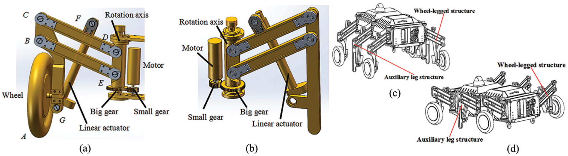
A 3D model of the wheel–leg/auxiliary leg structure: (a) 3D model of wheel-legged structure, (b) 3D model of auxiliary leg structure, (c) robot in leg state, and (d) robot in wheel state.
Figure 2(c) and (d) shows the rescue robot with leg state and wheel state, respectively. The four-bar structure can make the trunk of the robot change the motion state flexibly.
Rescue function modules
Rescue function modules can contribute to the completion of rescue missions. They also provide the basis for further relief work, which may include the stretcher structure module, extinguishing or supplemental oxygen structure module, and visual monitoring module.
Stretcher structure module—a stretcher can be used to transport goods or the wounded. When the stretcher is needed, it extends under the electromotor driving part of the robot from the bottom. Stretcher is two stages structure (Figure 3), and it is driven by one motor. The motor is fixedly connected with the frame, the pulley 1 is connected with the machine frame, the pulley 2 is connected with the auxiliary support plate, the pulley 3 and pulley 5 are connected with the first-stage stretcher, respectively, and the pulley 4 is connected with the second-stage stretcher. The winding way is also shown in Figure 3. When the motor rotates clockwise, the stretcher can be retracted. And the stretcher can be extended out when the motor rotates counterclockwise.

Structure diagram of stretcher.
Extinguishing/supplemental oxygen structure module—two kinds of emergency situations cannot be ignored: (a) When the rescue robot encounters unexpected fire, it should be able to put out the fire quickly to buy time for rescue workers to come into the scene. (b) When it comes in contact with a trapped person who has difficulty breathing, the rescue robot can provide oxygen on time to maintain vital signs before a medical staff arrives. So in this study, the extinguishing/supplemental oxygen structure module is designed. The structure diagram is shown in Figure 4.
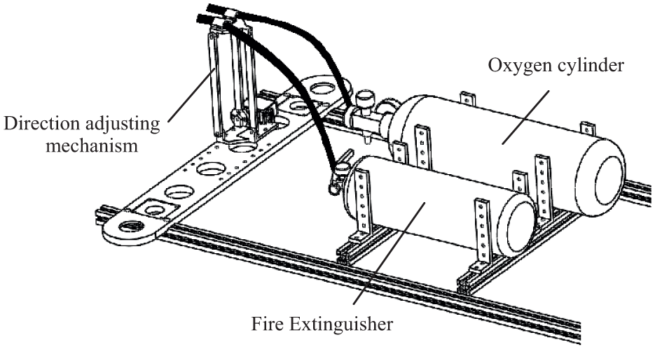
Structure diagram of extinguishing/supplemental oxygen structure module.
A visual monitoring module was also considered for real-time environment monitoring. Accordingly, the rescue robot can be seen in Figure 5.

Wheel-legged rescue robot.
Motion state analysis
Wheel state
The wheel-legged rescue robot can avoid obstacles with great flexibility by rotation of a four structure around vertical axis. The attitude change process is shown in Figure 6.

Attitude change process of the robot in wheel state.
When a wheel-legged structure of the robot is broken or is unable to move due to environmental constraints, the robot can only move through other three legs. However, the stable region can also change while the robot is in self-help mode; hence, stability should also be analyzed. If the stability is poor, the robot will be unable to work because of rollover. 36 The situation can also lead to slow robot; thus, static stability is analyzed in relation to robot speed.
The center of gravity (CG) projection method is used to analyze static stability. In this method, the necessary and sufficient condition for the object to be at rest and remain stable is that its CG is in the support surface. When the CG coincides with the center of the supporting surface, the object is in the most stable state and has the largest stability margin. If the rescue robot has n components, total mass is M, and mass of each component is mi, then the CG of each component is (xi, yi, zi). The CG position of the rescue robot can be expressed as

Because the structure of the rescue robot is very complex, the number of parts is a lot, so regardless of the mass of other structures, and only the mass of trunk is considered.
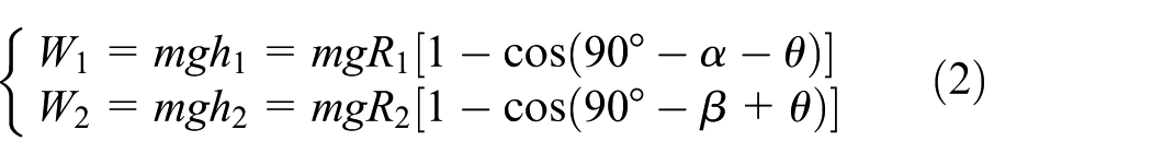
The movement process with one wheel-legged structure broken is shown in Figure 7. Suppose wheel-legged 4 is broken. At this point, the stable region is AhBhCh. The center of mass is on boundary line AhCh, and the robot is unstable. The only case for the robot to be able to save itself without changing the attitudes of the other three legs is that the robot is on an inclined plane. The inclined plane should be inclined downward along the ChBh direction (Figure 8). At this point, the CG position is in the stable region, and the robot is in a stable condition. The only case for the robot to be able to save itself without changing the attitudes of the other three legs is that the robot is on an inclined plane. W1 is the work of the robot which overcomes the gravity around Bh, and W2 is the work of the robot which overcomes the gravity around Ch. They can be shown as

Movement process with one wheel-legged structure broken.

Schematic diagram of stability.
If W1 > W2, the robot has the trend to tip over around Ch, and if W1 < W2, the robot has the trend to tip over around Bh. If W1 = W2, the robot is in the most stable state.
However, the environment of disaster scene is not ideal. Rescue robots should be able to move with one wheel-legged structure broken in a complex terrain.
As shown in Figure 7, when wheel-legged 4 is broken, wheel-legged 1–3 should be changed. The rotation angle of wheel-legged 1, 2, and 3 should be same. The left wheel-legged structures should move counterclockwise, and the right wheel-legged structures should move clockwise. At this point, when the robot moves with three wheel-legged structures only, the trunk should also be raised using a linear actuator. At this time, the center of mass can be guaranteed in the stable region.
Trunk lifting process
The robot should be able to change from wheel to leg state to cross obstacles easily and to prepare for the walking process. The distance between two contact points of wheel-legged structures will inevitably change when the trunk is lifted because of the structure characteristics (Figure 9). There are two ways to raise the trunk of the robot. The first transformation mode is to raise the trunk of the robot in motion. At this time, the four wheel-legged structures rotate the same angle around the vertical axis. For the second transformation mode, the four wheel-legged structures rotate 90° in turn, and the trunk is lifted without moving.
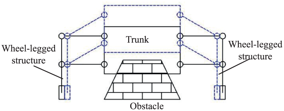
Schematic diagram of trunk lifting process.
In this case, the wheel-legged structures are the main structure to achieve trunk movement. Thus, kinematic and dynamic analysis is required to determine the link lengths and selection of the driving motor.
Figure 10 shows the diagram of the wheel-legged structure. The fixed coordinate system can be seen in Figure 10. The directions of the x and y axes are to the right and upward, respectively.
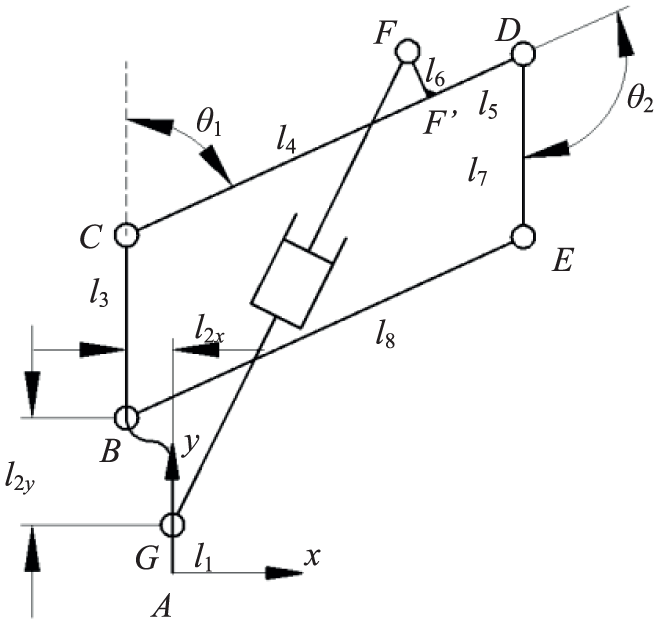
The wheel-legged structure.
First, the inverse kinematics should be studied. Accordingly, the vector equation is

According to the above equation, the rotation angle of the adjacent links and the movement law of the linear actuator can be easily obtained. Dynamic analysis was conducted to obtain the dynamic characteristics of each link. The force diagram of link AC can be seen in Figure 11. Link AC suffers the force

where
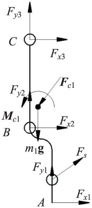
Schematic diagram of force analysis for link AC.
Leg state
When the rescue robot is in the leg state, it transforms into a six-legged robot. The gait should be analyzed according to the unique features of the structure.
There are two kinds of gaits. The first of which is shown in Figure 12(a). Leg structures L1, L3, and R2 comprise one set while L2, R1, and R3 are for the other set. The process of movement requires that when the trunk moves forward, one set of legs is in the support phase while the other is in the swing phase. The legs in the support phase should be kept parallel, which means the angle between the leg and the symmetry axis of the trunk is the same. Gait phase diagram for gait pattern 1 is shown in Figure 12(c).

Flowchart of gait movement: (a) gait pattern 1, (b) gait pattern 2, (c) gait phase diagram for gait pattern 1, and (d) gait phase diagram for gait pattern 2.
The second kind of gait can be seen in Figure 12(b). In this scheme, the six wheel-legged structures move forward using the motors and linear actuators from the initial state (state I) while the swing angles are retained. At this point, all the wheel–legs are in the support phase (state II). Subsequently, the supporting points of the wheel-legged structure are retained while the trunk moves forward. The angle between the wheel-legged structures and the axis of the trunk changes. Finally, the abovementioned gait movements are repeated to allow the robot to move forward. After moving, the robot returns to its initial state (state IV). Gait phase diagram for gait pattern 2 is shown in Figure 12(d).
The robot with the first kind of gait (Figure 12(a)) is more flexible and has faster movement speed. Conversely, the robot with the second kind of gait (Figure 12(b)) is more stable and has better carrying capacity. Therefore, choosing the suitable gait for the rescue robot depends on the field environment and rescue mission.
For the six-legged robot with multi-DOF leg structure, the trunk can move along the horizontal direction. Due to structural limitations, in the horizontal plane, the position of the connection point between the two legs and the trunk cannot be kept unchanged. The trunk will move up and down inevitably. The motion range of the trunk can be obtained by kinematic analysis of the wheel-legged structure.
Figure 13 shows the vertical distance of the trunk with different θ when the length of CD is 300 mm and the length of BC is 80 mm. The figure clearly shows that when θ increases, the motion amplitude of the trunk along the horizontal and vertical directions also increases.

Displacement of center of mass in leg state.
Parameter determinants for thewheel-legged structure
Structural parameters can affect motion performance. Accordingly, the parameters for the most comprehensive and best performance of the robot should be determined.
Mechanical properties
Mechanical properties refer to the forces of the ground to the robot, the internal forces of the wheel-legged structure, and driving forces. The main parameters that affect mechanical property are the length of BC, CD, AG, FF′, and F′D. Take the support force and driving force of linear actuator as an example. Suppose the mass of link AC is 2.5 kg, then the mass of link CD and BE is 1.5 kg, and the mass of the trunk is 85 kg.
Figure 14 shows the relationship of BC, CD, support force, and driving force. When the height of the trunk changes, the effects of the lengths of BC and CD to the support force and driving force also change. Structural parameters have different effects on mechanical properties. The different y0 corresponds to different change trends, and hence, the average value is taken as an object in the following analysis.
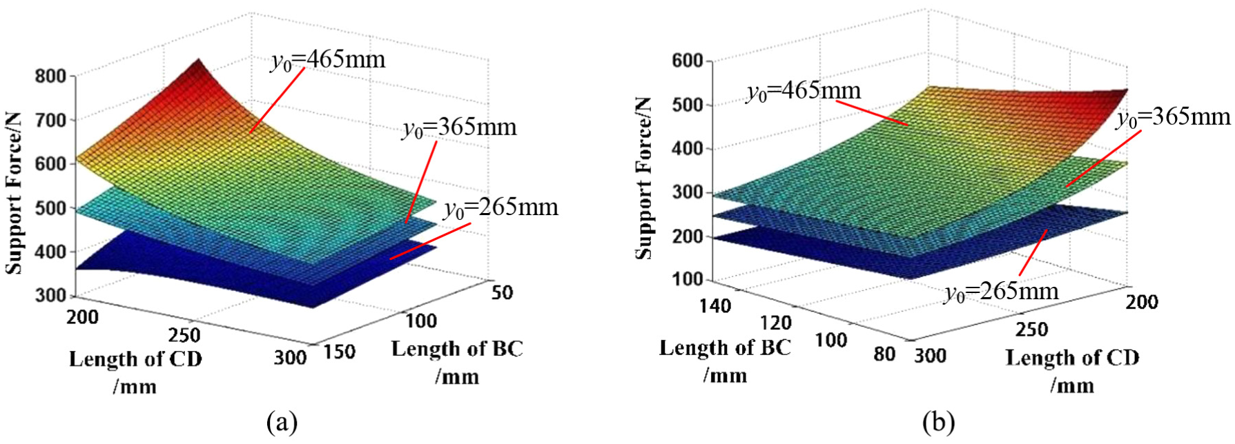
Relationship of structural parameters with mechanical properties: (a) length of CD and BC and support force; (b) length of CD and BC and driving force of the linear actuator.
Motion amplitude of the trunk
In gait movement, the movement amplitude of the trunk along the vertical direction should be as small as possible because too large movement amplitude will weaken the motion stability of the robot. However, a trunk with larger movement amplitudes along the horizontal direction has better obstacle capability. Equations (8) and (9) indicate that the main parameters affecting range of motion are the initial attitude angle θ and the length of the link of the four-bar mechanism.
The relationship of CD, θ, and motion distance of the trunk is shown in Figure 15, and the relationship of BC, θ, and motion distance of the trunk is shown in Figure 16. Decreasing θ also decreases the motion amplitudes of the trunk in both vertical and horizontal directions. A smaller θ corresponds to better motion stability; conversely, it also implies lower obstacle capability. Similarly, decreasing the length of CD also decreases the motion amplitudes of the trunk along both vertical and horizontal directions. The length of BC can be small. Therefore, the motion amplitude in different directions and terrain (including the size of the obstacle) should be considered synthetically to determine the structural parameters.
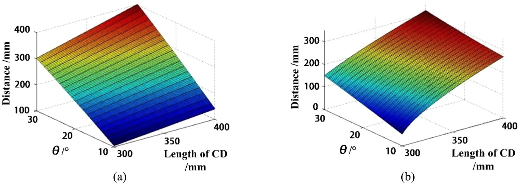
Relationship of CD, θ, and motion distance of the trunk: (a) horizontal direction and (b) vertical direction.

Relationship of BC, θ, and motion distance of the trunk: (a) horizontal direction and (b) vertical direction.
Movement stability
The farther the distance from the landing point to the trunk, the better the stability of the robot. The minimum stable region should meet the following conditions to ensure that the robot can maintain a stable state in different motion states

where Smin is the stable region of the robot in the leg state; S0 is the reference stable region, which is the area of trunk; σ1 is the ratio coefficient, which should be greater than 1. For the stability analysis, the projection distance of link CD is used as a reference value.
Based on performance analysis, the optimization objective function can be expressed as
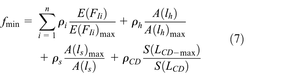
where E(FIi) is the expectation of forces, which includes the support force, driving force of linear actuator, and internal forces; A(lh) and A(ls) are the motion amplitudes along the vertical and horizontal directions, respectively; and S(LCD) is the projection length of link CD. Dimensionless method is used for the objective function. ρ is the proportional coefficient and
Constraint condition of the structural parameters.

A search algorithm was used to determine the optimal solution. Take values in the constraint condition randomly, and then calculate the support forces, motion amplitudes along the vertical and horizontal directions and projection length of link CD respectively according to equations (3)–(6). Then f can be calculated according to optimization objective function (7). The optimized parameters corresponding to the minimum objective function values were treated as demand results. The optimization results are as follows: BC = 84 mm, CD = 289 mm, FF′ = 66 mm, F′D = 117 mm, and AG = 79 mm.
Experiments
Figure 17 shows the prototype of the wheel-legged rescue robot. Its structural dimensions are the same size as the design dimensions. Because the robot is only a prototype, so the stretcher can only achieve telescopic function, but cannot carry heavier items or wounded.
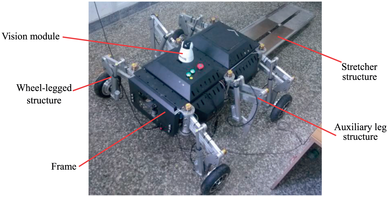
Prototype of the rescue robot.
The overall control flowchart is shown in Figure 18. First, the system is initialized by the host computer, which makes the robot is in the initial state. Because the robot has many motion states, so the robot should judge whether the state converting command is received or not. If the state converting command is received, the system information is read to determine which state to be in. If the robot does not receive state converting command, the robot should judge whether to receive speed setting command or not. At this time, the velocity of the robot can be adjusted in real time in different motion states, and the obstacle avoidance movement can be achieved. Through above control mode, the motion state of the robot can be effectively controlled. In the process of obstacle avoidance, ultrasonic obstacle avoidance algorithm is used. First, the distances which the ultrasonic measures are obtained, and threshold of each direction is adjusted according to movement speed of the robot. On this basis, the real-time measurement value is compared with the threshold. When the measured value is greater than the threshold value, it shows that there is no obstacle or obstacle is far from the robot. The robot can maintain its original motion state. But when the measured value is less than the threshold value, it shows that there are obstacles near the robot. Because ultrasonic sensors are installed in different positions of the robot, so it is necessary to determine if the obstacle direction is consistent with the movement direction. It can be determined whether the robot needs to adjust the state of motion. The control flowchart for obstacle avoidance is shown in Figure 19.

Control flow of wheel-legged rescue robot.

Control flowchart for obstacle avoidance.
Rescue robot obstacle avoidance process is shown in Figure 20. Figure 20(a) indicates that the robot encountered obstacles in the wheel state in the current motion direction, and Figure 20(b) shows that the robot changes the attitude of the wheel-legged. Figure 20(c) shows that the robot changes the movement direction, and finally realizes obstacle avoidance.

Wheel-legged posture transformation process.
Figure 21 shows the moving trail of the center of mass. The solid and dotted lines are for the actual and theoretical values, respectively. The robot can turn to a corner at a small angle (right angle) and avoid obstacles by changing of the movement of the legs. In Figure 21, the actual and theoretical values are quite similar, thereby suggesting the movement can meet the requirements of a rescue robot. The robot can also transform to a wheel-legged structure in leg state to avoid obstacles.
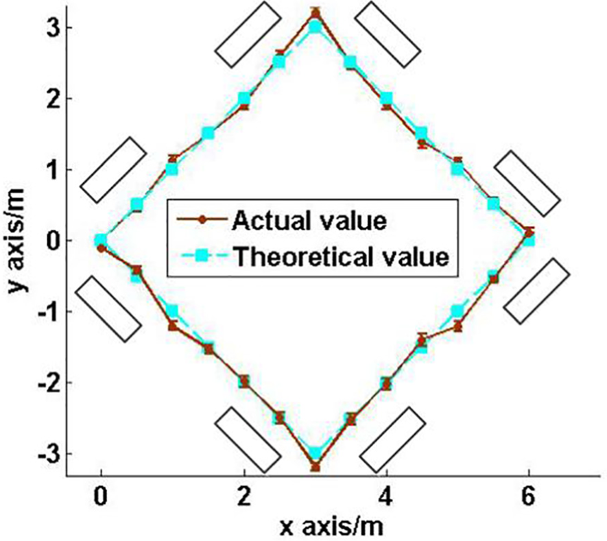
Moving trail of center of mass in wheel state.
Figure 22 shows the trunk lifting process. When the robot encounters obstacles, but obstacles are small, the robot can raise the trunk to cross obstacles. Figure 23, which corresponds to the first transformation mode, shows the trunk lifting processes. The vertical height of the center of mass of the trunk increased from 400 to 800 mm in 3 s. If the robot needs to lower its trunk height, it also needs to change the wheel-legged attitude and reduce the height using the same method.

Trunk lifting process.
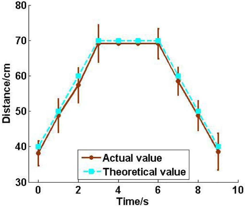
Variation in trunk movements.
If the robot changes the height of the trunk in the second transformation mode, the trunk undergoes a similar changing law. The only difference is that the robots will take longer under the second transformation mode. The actual value is smaller than the theoretical value because of the machining gap.
Figure 24 shows the leg state of the rescue robot with the first kind of gait being used. Figure 25 shows the movement law of the trunk. Similar to previous observations, motion error was caused by machining and control errors, but they can be corrected by a control supplement. Results verify that the rescue robot can complete its expected function.

Leg state of rescue robot: (a) L1, L3, R2 in supporting phase and (b) L2, R1, R3 in supporting phase.

Movement law of trunk.
Conclusion
A rescue robot is designed in this article, which can replace rescue workers in complex environments and complete search-and-rescue missions. To address the requirements of disaster relief, the robot was designed as four-bar wheel-legged structure with rescue function modules. The wheel-legged structure has the advantages of high carrying capacity, easy control, and simple structure to adapt to a complex disaster scene. The rescue function modules can help rescue workers to complete the rescue work. The different motion states were analyzed. To determine the most comprehensive and best performance of the robot, an optimization objective function was proposed according to the motion characteristics of robot, which include mechanical property, motion amplitude of the trunk, and movement stability, and the parameters optimization is conducted. An experiment was conducted to prove the feasibility of the structural design. Findings verify that the wheel-legged rescue robot can achieve good motion performance. Future research direction may focus on conducting motion performance and rescue function tests in complex terrains to simulate a disaster environment.
Footnotes
Handling Editor: Yunn-Lin Hwang
Declaration of conflicting interests
The author(s) declared no potential conflicts of interest with respect to the research, authorship, and/or publication of this article.
Funding
The author(s) disclosed receipt of the following financial support for the research, authorship, and/or publication of this article: This work was supported by the Natural Science Foundation of Jiangsu Province of China (grant no. BK20160185), the National Science Foundation for Young Scientists of China (grant no. 51705201), the Fundamental Research Funds for the Central Universities (grant no. JUSRP11718), the Foundation of Jiangsu Key Laboratory of Advanced Food Manufacturing Equipment and Technology (grant no. FM-2016-08), the Jiangnan University Student’s Innovation Training Project (grant no. 2016343Y), and the Undergraduate Innovation and Entrepreneurship Training Program of China (grant no. 201710295078Y).