
Abstract
A multi-objective optimization method is proposed for optimal motor selection, control, and planning for a point-to-point trajectory of a robot manipulator, where three objective functions are proposed to be minimized: the total weight of actuators, the execution time and velocity transitions between planned points, and the tracking error of the task. A concurrent approach is proposed where the powertrain dynamics of the robot is taken into account, that is, motor, gearbox, and load at each actuated joint. To solve the concurrent optimization problem, a genetic algorithm is used, where a representative set of non-dominated solutions form the Pareto-front. The method is tested for a 3-degree-of-freedom manipulator by selecting a particular solution.
Keywords
Introduction
The powertrain of a robot manipulator is composed of motor, transmission, and load at each actuated joint and provides the required torque to yield a desired behavior of the robotic system. Thus, the powertrain has a high impact on the whole performance of the robotic system, where a proper selection of motors is of great importance to ensure an efficient performance.
The parameterization of a powertrain model may consist of the motor selection and transmission unit that can drive a given load profile. In mechatronics systems, the optimal selection of a motor coupled to a gearbox or reducer has been addressed by several authors.
In Roos et al., 1 an optimal motor/gear ratio combination is obtained with a specific load profile that can do the required task, considering that the worst case of an inertial load is a priori known.
In Van de Straete and colleagues,2,3 an optimal motor selection method is presented by analyzing separately the motor and load characteristics for a given task, so that a motor is selected from a set of candidate motors that performs the required load, and it best satisfies a desired additional criterion, such as weight or size.
Common motor selection methods consider statistical parameters (known torque and motion profiles) to find candidate combination of motor reducer in order to satisfy a desired criterion. However, motor and load torque profiles depend on the dynamical response of the robot to perform the given task; thereby, in this article, load profiles are given by the dynamic motion equations of the robot. The motors, gearboxes, and loads of the powertrain are considered simultaneously for the proposed parameter motor selection method.
Since the weight of each selected motor changes the inertial parameters and the manipulator payload, minimal total motors weight on the robot is considered in order to increase the load-carrying capacity and operational speed of the robot with lower energy consumption. 4
In a motor selection method, there are required characteristics of motors, reducer, and loads that should be considered to choose the best coupling unit which depends on their own limits and physical capabilities. In previous works,5–8 thermal, electrical, and mechanical characteristics have been deeply analyzed for optimal motor selection for the combined system motor–reducer load. Some of these characteristics are considered in this article as constraints of the optimal motor selection to avoid overheating, overexertion, and damage on the powertrain.
To obtain a solution for a point-to-point planning of the robot, the control effects of actuators and planning parameters are considered in the motor selection process. This led us to solve, simultaneously, the closed-loop dynamic response of the robotic system in order to ensure that candidate actuators can perform properly a desired planned path. For this purpose, a proportional–integral–derivative (PID) controller is applied at each joint, since it is a widely used control technique in the industrial field and it offers one of the simplest and yet efficient solutions to many real-world control problems. 9 To ensure proper motion of the robot when performing the task, the tracking error during the task is proposed as one of the objective functions to be minimized.
Concerning to the point-to-point planning method, fourth- and fifth-degree polynomials are considered to connect initial and intermediate points with desired boundary conditions (desired initial and final positions, velocities, and accelerations), since composite splines with connected low-degree polynomials is a simple method to create curves with continuous transitions at via points. As planning parameters, the time executions and imposed positions and velocities at via points are used, where the total distance of planned path and cycle time is proposed as an objective function to minimize. This planning method is based on the literature,4,10 where fourth- and fifth-degree polynomials are used to connect multiple via points to do a task.
Three objective functions are proposed to be minimized at the same time, subject to the closed-loop dynamics and capabilities of actuators. Thus, a concurrent approach strategy is proposed instead of traditional sequential methodology (that solve independently each optimization problem), since the solution for the combined system may not be optimal. 11 In contrast, a concurrent optimization method deals with multi-objective optimization problems, obtaining solutions for the combined system.12–14
Then, dynamical parameters are considered for motor–gearbox selection, control, and planning method in a concurrent multi-objective optimization problem, in contrast to classical methods where only motor selection is considered and torque and motion profiles are a priori known to the selection purposes. The constrained multi-objective optimization problem with a concurrent approach is solved by a Non-dominated Sorting Genetic Algorithm-II (NSGA-II algorithm 15 ), since it is an evolutionary algorithm widely used to deal with multi-objective optimization problems, 16 and has been successfully used for path planning4,10,17–19 and concurrent design.20–22
This article is organized as follows. Section “Point-to-point trajectory planning strategy” describes the applied point-to-point planning method. In “Dynamic model of the robotic system,” the whole model in closed-loop dynamics of the robot is stated. In the section “Characteristics of actuators on the powertrain,” criteria of feasible actuators on the powertrain are given. The proposed decision variables to get a feasible solution of the combined system are presented in “Decision variables.” In section “Objective functions,” the objective functions considered for the optimization problem are proposed. “Concurrent optimization and genetic algorithm” shows both the concurrent optimization problem and the NSGA-II algorithm to solve it. In section “Application to a particular case and simulations results,” the application of this method to a particular case is shown, where simulation results of chosen non-dominated solutions are presented. Finally, the section “Conclusion” comments representative results and concludes the article.
Point-to-point trajectory planning strategy
Considering a direct-drive robot with n-joints, that is,
Then, an interpolation of points can describe the required path with a desired execution time


Let us consider that there are


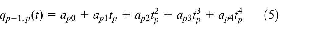
Fourth- and fifth-degree polynomials are used to connect intermediate points for planning the total transition path. This connection is used at each joint, as it is shown in Figure 1. Then, among the point
where


where


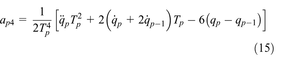
where the intermediate acceleration


Trajectory planning at each joint of the robot.
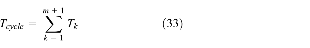
The segment from the mth to the final point can be described by

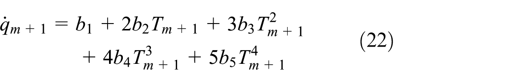
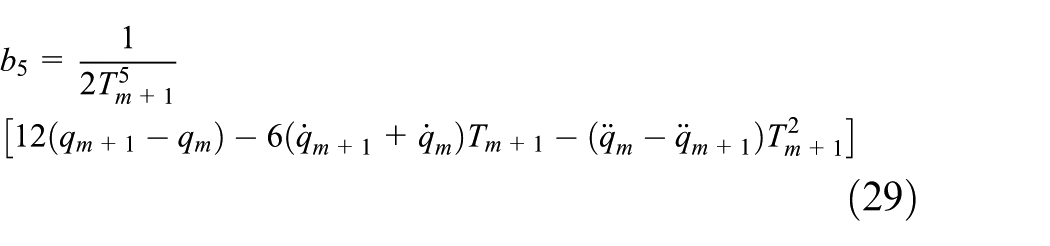
where for the quintic polynomial,


where


So, the total planning parameters are the joint angle intermediate points
Hence, the following continuity conditions in equations (30)–(33) have to be verified in order to generate a suitable connection between points
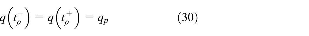


To ensure a proper behavior of the robot through a desired planned path, according to capabilities of actuators, the dynamics of the robotic system in a closed-loop control can be considered to get a dynamically feasible motion through the desired trajectory. For this, the robotic system is considered as follows.
Dynamic model of the robotic system
The powertrain model involves three main parts: motor, gearbox (transmission), and load (mechanism); a schematic representation is shown in Figure 2.

Schematic view of powertrain model on the actuating joint.
Considering a direct-drive rigid robot with

where for the ith actuated joint,

On one hand, the actuator dynamics of the robot can be given by a matrix representation as

where
On the other hand, the dynamic equations of motion for the mechanism can be described by

where
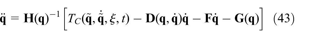
Considering the actuators and the manipulator dynamics, a dynamic model of the whole system can be obtained as

where
Taking into account the dynamics in a closed-loop control, the tracking errors are defined in equations (39) and (40)


where
In order to minimize the tracking error, a PID control is proposed, where


Characteristics of actuators on the powertrain
In a typical velocity–torque curve of an electric motor,

Operating zones for an electric motor in a
The continuous torque
Since the motor/gearbox coupling is considered on the powertrain at each joint, the maximum load torque, continuous output torque, and the permissible motor velocity on the gearbox connection should not exceed the limit values given by the manufacturer for each gearbox
The continuous output torque of the gearbox
The RMC torque value also reflects typical endurance curves of steel or aluminum and is a bearing fatigue on different load cycles, which is relevant to gearbox lifetime. In addition, it has been used in robotic applications to select/size a gearbox required for a task.23,24
Selection criteria for feasible set of actuators
Based on the above characteristics of actuators, a criterion of feasibility can be proposed when a new set of actuators is desired to be installed on the robot. For this, the characteristics of a feasible set of actuators on the powertrain to perform a desired task can be considered as constraints of the selection process of actuators as follows.
Motor characteristics
The operation requirements considered for a usable motor, at each ith joint of the robot, are given by equations (44)–(46)


where
Gearbox characteristics
The characteristics required for a feasible gearbox at each ith joint are given by equations (47)–(49)


where
Using the above-mentioned characteristics, the overexertion of components and undesirable motion can be avoided when a new set of actuators is installed, considering the dynamics of the overall system and the new capabilities of the selected actuators.
Decision variables
The following decision vectors are proposed in order to assign the design, control, and planning parameters that are simultaneously involved to get a feasible selection and control of motors and gearboxes to follow a viable planned path.
Discrete vector for selection of actuators
Consider two decision vectors


Since the indexes of motors and gearboxes are related to available components from a commercial catalog, the design parameters of motors and gearboxes are considered to be known for each specific index number. Then, the parameter values given by the manufacturer for the

Actuators of the robot and index selection for the ith joint.
Continuous decision vector for control
Consider a decision vector
The controller gains are considered positive, that is

Continuous decision vector for planning
A decision vector
Objective functions
Total weight of motors and gearboxes
The objective is to minimize the total weight of motors and gearboxes on drive train, by selecting a new feasible light-weight set of components on the powertrain, that is

where
Trajectory tracking
To ensure proper motion of the robot, minimization of the trajectory tracking error during the planned path is proposed, that is
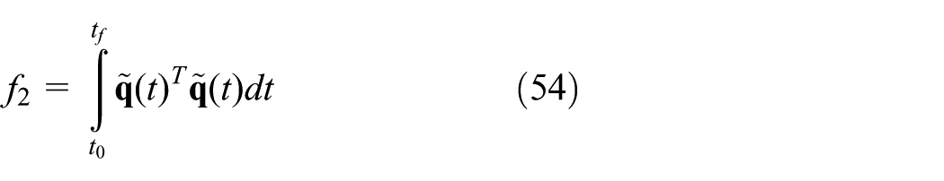
where
Total time-space of the planned path
The objective function

where


According to the interpolation of points that describes the planned path from the initial to the final point of the task,
Constraints
The dynamic equation of the whole system in closed-loop control is considered as a constraint to get feasible motion of the robot. However, when a candidate set of motors and gearboxes is installed, there are changes in the inertial parameters whose effects modify the dynamic performance of the robotic system.
These changes on the inertial parameters are the total weight, inertial contributions, and mass center at each joint of the robot, which are considered as follows.
Effects in robot dynamics
It is known that the governing equation of the arm motion, equation (37), can be obtained using the Euler–Lagrange formulation.
25
In general, the inertia matrix,

where
The

where the coefficients
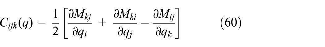
are termed Christoffel symbols of the first type,
25
computed using elements of the inertia matrix
The kth element of the vector of gravity,
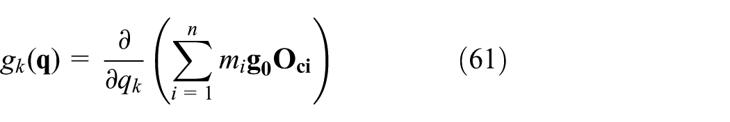
where
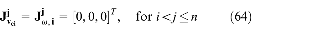
According to the type of joint, prismatic or revolute joint, the jth column of the Jacobian matrices can be obtained as

where

where
Let us consider that the expressions

Now, it is clear that the dynamic equations of the mechanism depend on inertial parameters of weight
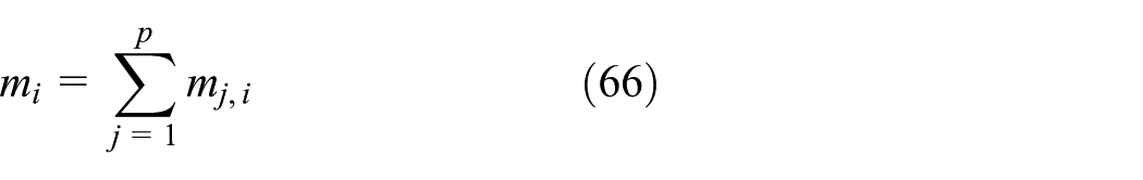
where
The change for total mass center at link

where
Consider the location of the total mass center


Let

Under Steiner’s theorem, the total inertia of the ith link can be calculated with respect to the mass center

where

each
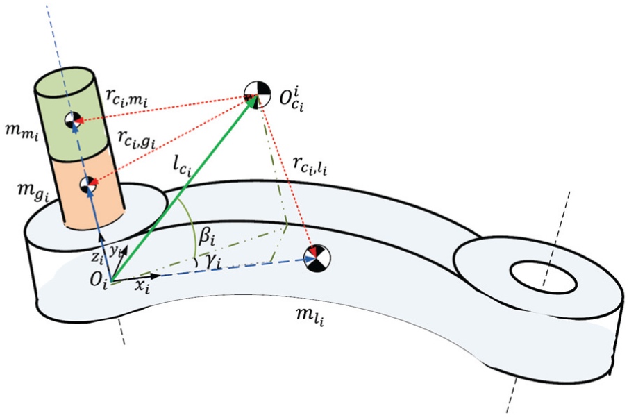
Mass center location with respect to the total mass center of the frame i, when a motor/gearbox combination is installed at each link of the robot.
Concurrent optimization and genetic algorithm
Multi-objective optimization problem
A multi-objective optimization problem is stated with three objective functions (equations (53)–(55)). For this, it is proposed to find a decision vector

in order to minimize the objective function vector

subject to the following:
The dynamics of the robotic system equations (42) and (43), considering changes in inertial parameters, equations (66)–(70), on the mechanism dynamics equations.
Constraints for bounded gains of control (equation (52)).
The boundary conditions, equations (3) and (4) of planning parameters, and the constraints to consider a bounded transition point and to obtain a suitable connection (equations (30)–(32)).
The criteria of feasibility of actuators related to characteristics of motors and gearboxes, given by equations (44)–(49), and bounded indexes of selection, that is, equations (50) and (51).
NSGA-II algorithm
The NSGA-II algorithm is able to find a spread of non-dominated solutions and convergence near the true Pareto-front compared to classical genetic algorithms and is widely used for mechatronic design problems.
A flowchart of an iteration of the used NSGA-II is shown in Figure 6.

One iteration of the NSGA-II algorithm.
The steps of the algorithm are as follows:
Randomly create an initial population
Create a new population
Verify feasibility of constraints and evaluate each objective function for each individual
Merge
Sort
Select the best
Crowding distance application on fronts
Go to next-generation
Application to a particular case and simulation results
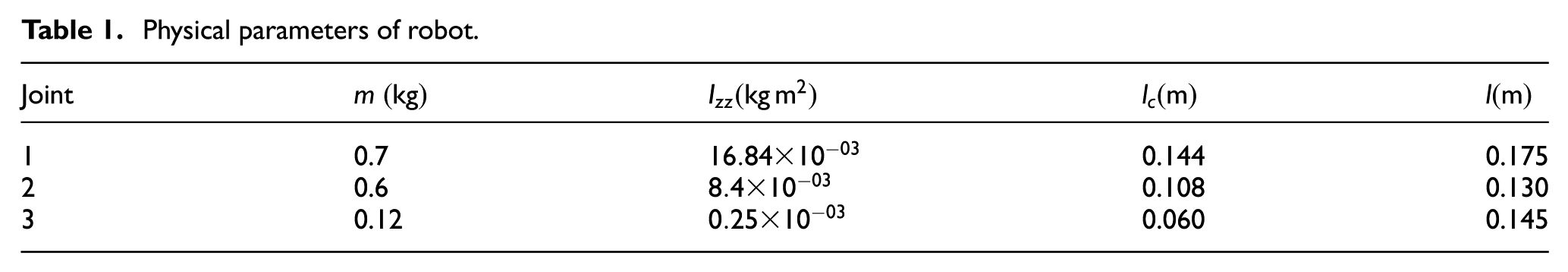
A 3-degree-of-freedom (DOF) planar robot shown in Figure 7 is used as case study. The physical parameters used for the robot model are shown in Table 1. More details of the robot can be found in Muro et al. 26

Case of study: 3-DOF robot.
Physical parameters of robot.
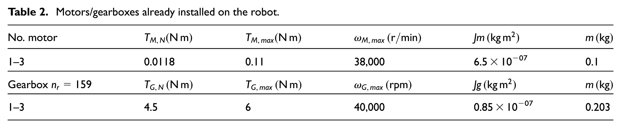
The joints are actuated by brushless DC servomotors, Micromo Electronics Inc. brand motor, each one coupled to a gearbox. Details of actuators are shown in Table 2. However, the actual mechanism cannot operate in some regions of its workspace due to unsuitable motors and gearboxes already installed on it. Then, a redesign of the robot with a proper selection of motors and gearboxes is needed.
Motors/gearboxes already installed on the robot.
Assuming that we desire to take the robot from an initial to a final pose inside the whole workspace, a new set of components has to be installed to accomplish the task. Thus, the objective of this application is redesign the powertrain of the robot by an optimal selection of commercial motors/gearboxes and assign a proper set of control and planning parameter values. In order to optimize the point-to-point trajectory planning, the dynamics of overall system and capabilities of the selected actuators are considered.
The available motors and gearboxes proposed for the selection criteria are presented in Tables 3 and 4, respectively. The components in the catalog lists are divided by groups, where combinations between brushless DC motors and gearboxes can be coupled, as long as both remain in the same group. This group division is created according to the compatibility of coupling that is allowed by the manufacturer (Maxon Motor brand).
Motor catalog list.

Gearbox catalog list.

The three motors and gearboxes already installed on the mechanism are considered in the catalog lists. They can be found in Group F, motor 42, and gearbox 28 for each joint. Then, the initial condition for the indexes of selection
The initial condition of the mechanism is proposed at
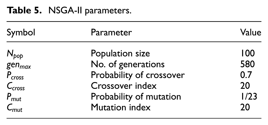
A population of 100 chromosomes is proposed for the NSGA-II algorithm, which yields a set of non-dominated solutions and all constraints satisfied at 580 generations. The parameters used for the algorithm are shown in Table 5.
NSGA-II parameters.
A set of non-dominated solutions is obtained using the NSGA-II algorithm with the resulting Pareto-front shown in Figure 8, where the trade-offs among objective functions can be seen, that is, light-weight components allow to increase inertial capabilities to move the robot with less energy, but the actuator capabilities are more limited than others with more weight, and then, it is more difficult to ensure the minimal time-space to do the task; however, once the end-effector is near to the planned path, they present better tracking of the desired path than using heavier components. In a contrary manner, by selecting higher capabilities on actuators, the weight increases, which means that they require higher torque profiles to perform the task; however, since their capabilities are higher, they can handle the robot along the planned path with less time-space, but not with the best tracking of the desired path.

Pareto-front obtained. V1, V2, and V3 are selected chromosomes to compare results.
Post analysis of Pareto-front has been widely addressed, where some authors suggest that selecting the nearest non-dominated point to origin axes of objective functions (also known as the Utopian point) should give a equality-weighted solution; 27 others consider that the best trade-offs region is in the knee of the Pareto-front. However, in a multi-objective optimization problem, the best solution turns subjective, since a non-dominated solution cannot be improved in value without worsening some other objective, and finally, the user has to subjectively select one solution in order to best satisfy the desired objectives for the required task. In addition, these solutions may not be the most satisfactory for the user and just represent local solutions from a set of feasible possibilities to choose. Therefore, we consider to obtain all the spread set of non-dominated solutions to form the Pareto-front.
For comparison purposes, among possible solutions at the Pareto-front, three chromosomes of the non-dominated solutions are selected, V1, V2, and V3, whose solutions satisfy all considered constraints. See the selected chromosomes in Figure 9.
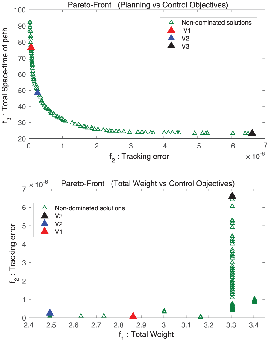
Pareto-front obtained. V1, V2, and V3 are selected chromosomes to compare results.
The position and velocity profiles are shown in Figure 10, where actuators for solution V3 give the heaviest set of components; however, it presents minimum cycle time
Indexes of selection for motors and gearboxes, where
Intermediate conditions and execution time,
Control gain values for the PID controllers

Positions, velocities, and intermediate points for solutions V1, V2, and V3. Joint 1 is represented by the continuous lines (-), Joint 2 with dash lines (- -), and Joint 3 with the dotted lines (.). The intermediate points are shown with black circles.
The obtained velocity profiles also are shown in Figure 10, where V1 gives the lowest velocity profile and consequently the lowest response. This can be explained by the fact that lower values of inertial parameters can increase velocity and load capacity, but with the disadvantage of limited capabilities on actuators; as a consequence, the input motor torque cannot be increased without overheating to take the robot through the planned path.
The trajectory at Cartesian space is shown in Figure 11, where solution V3 got the shortest distance traveled in joint and Cartesian spaces. In contrast, this solution obtained the highest tracking error, as shown in Figure 12.

Planned trajectory solutions V1, V2, and V3.

Tracking errors during the task for solutions V1, V2, and V3. Error for Joint 1 is represented by the continuous lines (-), Joint 2 with dash lines (–) and error for Joint 3 with the dotted lines (.).
Input motor torques and load torques are shown in Figure 13. Since selection and control effects are simultaneously considered, it can be seen that a heavier set of actuators requires higher input motor torques to perform the planned path.

Required motor torques and load torques for solutions V1, V2, and V3. Joint 1 is represented by the continuous lines (-), Joint 2 with dashed lines (–), and Joint 3 with the dotted lines (.). The intermediate points are shown with black circles.
Load torques seem to be at the same maximum torque for the three solutions; however, there are many possible motors to be combined with the gearbox to follow the given load, where feasibility depends on the closed-loop response of the combined system for an injected control input. The controller is able to maintain candidate motor within their own range of continuous and dynamical ranges, selecting feasible actuators depending also on cycle time and objectives of planning. Therefore, not only torque and motion profiles are enough for proper selection of motors but also control effects are of great importance to obtain feasible solutions. Then, selection methods where load torques and motion profiles are known a priori may not result optimal for the closed-loop dynamics.
Conclusion
The selection of components is essential for the planning trajectory problem to achieve a desired performance and motion of the robotic system according to the capabilities of actuators, and vice versa, according to actuators installed on the robot, a dynamically feasible path can be generated to obtain an optimal cycle time of the task, since it directly affects the dynamic performance of the system.
Considering control effects in the selection process is of great importance, so much that the motor response, obtained from a given control input, may be decisive in determining motor feasibility for the required task. Then, concurrent selection and control method provide feasible solutions in a closed-loop dynamics for a specific task.
The inertial parameter changes, such as total weight, inertia, and mass center of each link, are caused by adding a set of components on the powertrain, and they should be considered to ensure a proper performance of components under the dynamic motion of the robotic system.
A light-weight set of components increases velocity and inertial capabilities to move the robot with lower energy consumption; however, their capabilities are more limited. In a contrary manner, a heavy-weight set of components decrease payload and velocity, requiring higher torque profiles and more energy consumption to move the robot faster, but capabilities are higher than lighter components.
A concurrent design approach is a crucial strategy to deal with different objectives that are involved in the interaction of many sub-systems of the overall system with many objective functions to optimize a design, which are conflicting with each other at the same time. Considering the different trade-offs between motor/gearbox selection, minimum tracking error, and cycle time for a robotic system, the user has to select a solution that satisfies the subjective preferences to do the desired task.
Footnotes
Acknowledgements
We would like to thank the reviewers for their insightful comments on the paper, as these comments led us to improvement of the work. M.A.M.-A. wish to thank the Government of Mexico (Instituto Politécnico Nacional, SNI, SIP-IPN, COFAA-IPN, and CONACyT) for providing necessary support to carry out this research work.
Handling Editor: Long Cheng
Declaration of conflicting interests
The author(s) declared no potential conflicts of interest with respect to the research, authorship, and/or publication of this article.
Funding
The author(s) disclosed receipt of the following financial support for the research, authorship, and/or publication of this article: This work was partially supported by the National Council for Science and Technology, CONACyT, Mexico, under the grant 254329.