
Abstract
An improved rotating high-frequency signal injection method based on a finite impulse-response filter for state estimation of bearingless permanent magnet synchronous motor sensorless control is developed in this article. A novel equiripple optimal approximation finite impulse-response filter, which can achieve that the maximum error of pass-band and stop-band is minimum than other finite impulse-response filter under the conditions of the same-order magnitude, is introduced to extract the high-frequency current signal and realize minimum extraction error. The rotor position error signal can be extracted using heterodyning processing to the high-frequency current. The proposed method can effectively eliminate the synchronous shaft filter and reduce the complexity of the system. Linear-phase compensation is used in the finite impulse-response filter to achieve minimum delay of rotor speed and position estimation. The BPMSM sensorless vector control system is set up based on this estimation approach. Simulation results indicate that the proposed method integrated off-line optimization of a finite impulse-response filter and linear-phase compensation can accurately estimate the rotor position and speed in the full-speed range.
Keywords
Introduction
Bearingless motors fold the magnetic levitation control winding around the stator slot by taking advantage of the similarity between the structure of the magnetic bearing and that of the motor stator. Its rotor can rotate and be supported at the same time by controlling the two sets of windings of which the pole pair difference is one. The advantages of bearingless motors are no contact, no lubrication, and no mechanical friction rotation. 1 Bearingless motors have several excellent qualities such as smaller volume, higher power density, no pollution, no need for lubrication and sealing, and high stability. They have broad application in turbo molecular pumps, centrifuges, electrical energy storage, aerospace2,3 and agricultural engineering, life sciences, and other high-speed and ultra-high-speed drive fields.
Bearingless permanent magnet synchronous motors (BPMSM) usually adopt rotor field-oriented vector control method to realize decoupling control of the electromagnetic torque and levitation force. 4 The key to this method is to obtain accurate rotor position and speed. Traditionally, the position and speed of the rotor space is detected by mechanical sensor detection (a photoelectric coding device, a rotating transformer, etc.). It has several installation problems including connection and reliability. Especially for the bearingless motor, the high-speed and ultra-high-speed performance will be affected by mechanical sensor installation. Therefore, in recent years, sensorless control technology has become an important area of study for bearingless motors.
At present, in accordance with the applicable scope of motor operation, sensorless control technology is mainly divided into two categories: (1) state observation and (2) high-frequency (HF) signal injection.5–9 This method extracts the rotor speed and position information directly or indirectly from the back electromotive force (EMF) of the motor, and its dynamic performance is good. However, when the speed is low or null, it will fail because the back EMF is too small to be detected. Accordingly, these methods apply only to medium- or high-speed operations. (2) In HF signal injection10–15 method, by applying HF excitation, the full range of rotor position detection including zero speed is effectively realized by tracking the rotor space salient effect of the motor. It is not sensitive to the change of motor parameters, and its robustness is excellent because of the rotor space salient effect tracking. In recent years, many scholars have studied and improved this technique. In Wang et al., 11 the rotating HF injection method was adopted for the rotor initial position and rotor speed estimation of a built-in permanent magnet synchronous motor (PMSM). Synchronous rotating filter processes, a two-phase static rotating coordinate transformation and a Butterworth second-order band-pass filter, were used to extract the negative-phase sequence current in the two-phase stationary coordinates. In Bolognani et al., 12 a discrete Fourier transform (DFT) was adopted to extract the HF current envelope, which is the control signal of the rotor position error. In Shinnaka, 13 the elliptical HF voltage, which changes with speed, was added to the motor; and the two-phase HF current signal multiplication was added as the phase-locked loop (PLL) input signal to obtain the rotor position and speed estimation from zero speed to the rated speed. Various defects exist in these methods such as complicated theory, cumbersome processes, and a large amount of calculation. Hou et al. 14 combined the pulse vibration of the HF signal injection method and a model reference adaptive. In Foo and Rahman, 15 the rotating HF signal injection method and a sliding mode observer were combined to realize the rotor position and speed estimation of the PMSM in the full-speed range. The switch principle should be designed in these composite algorithms to ensure that the speed and rotor position estimation in the transition zone is accurate.
This article studies the rotating HF signal injection method to simplify the system design process. By extracting HF current signal, the rippled best-approximation finite impulse-response (FIR) filter is designed off-line to ensure that the HF current signal is accurate. Using heterodyning processing to the HF current directly, a Chebyshev infinite impulse-response (IIR) low-pass filter effectively extracts the rotor position error signal to save a synchronous axis filter unit and reduces the complexity of the system. Meanwhile, the minimum delay time estimation of rotor speed and position is realized by compensating for the phase lag of the FIR. Finally, a BPMSM sensorless vector control system is constructed to verify the effectiveness of the proposed method.
Rotating HF signal injection method
The essence of the embedded BPMSM rotating part is PMSM. Under the static coordinate system, the motor voltage model can be represented as

where
The HF voltage vector

where
When

If there is only one space salient-pole in the salient-pole pitch of the motor, then in the synchronous rotating coordinate system, the stator inductance matrix can be expressed as

where
In the two-phase static coordinates, the inductance matrix can be expressed as

where
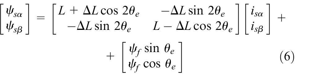
where
Due to the convex polarity of the rotor structure of the built-in PMSM, injected HF voltage can drive HF current component with the magnetic pole position information from the stator winding. By equations (3) and (6), the HF current expression can be obtained under a two-phase static coordinate, and it is simplified as follows

where
Using heterodyning processing to the two-phase HF current

with low-pass filtering for

When the magnetic pole position identification error is small,
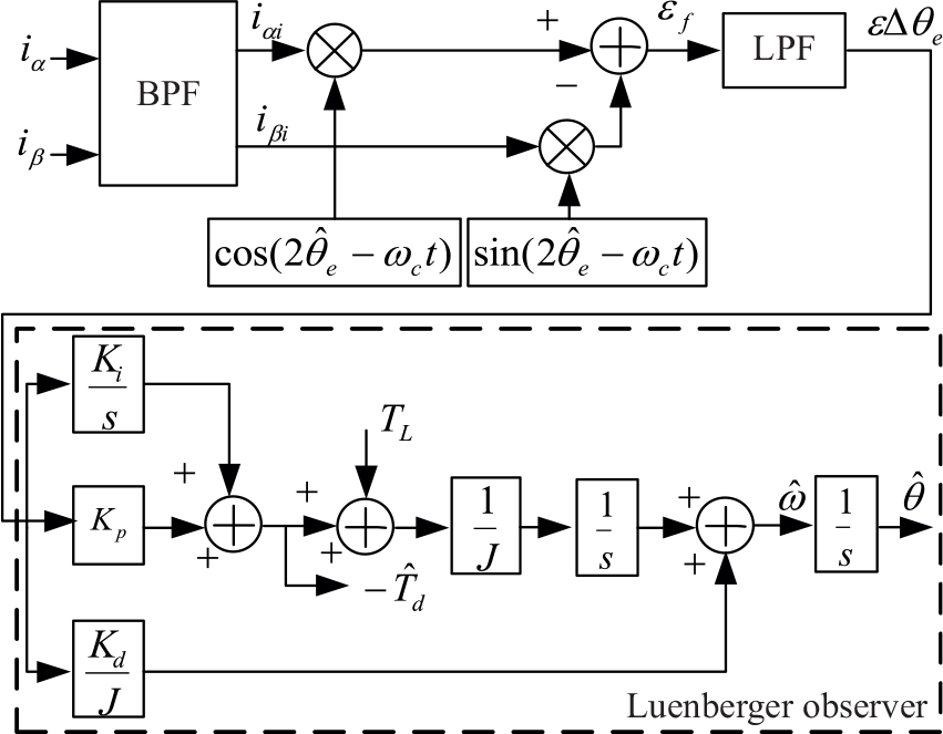
Structural diagram of rotor position extraction.
Design and compensation of the best-approximation linear-phase equiripple FIR filter
Signal-processing quality directly determines the estimation precision of rotor position and speed in the rotating HF signal injection method. To ensure the HF current signal amplitude distortion and phase lag will reach a minimum, this article uses the best-approximation linear-phase equiripple FIR filter to extract the HF current signal. The filter has linear-phase characteristics, and the pass-band and stop-band maximum error is minimal in the same order. By introducing this filter to the HF injection method, the system tracking ability and quick response can be improved.
FIR filter design
Assuming that impulse response of the FIR filter meets the condition that

Assuming that

The essence that uses the equiripple optimal approximation method to design linear-phase FIR filter is to solve the

where A is the approximation of
The Chebyshev approximation theory holds that

where
Step 1. Setting

where

where
Step 2. Checking whether a frequency point exists to meet the condition of
Step 3. Repeat Step 2 and adjust the frequency of the crossing point group.
Step 4. Calculate
A flowchart of the design process for FIR filter is given in Figure 2.
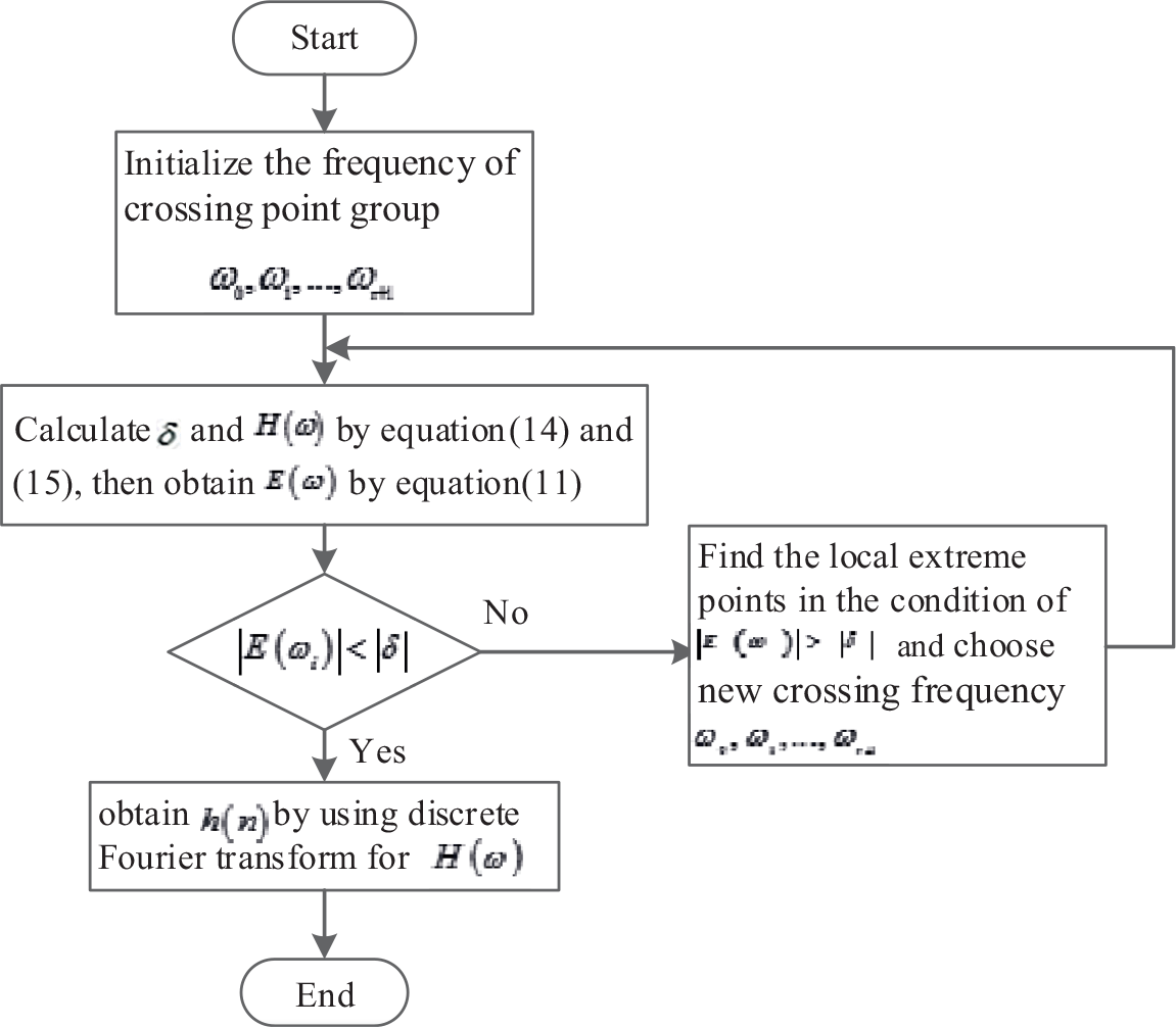
The flowchart of the design process for FIR filter.
The magnitude and phase response of the equiripple optimal approximation FIR filter designed on the basis of the above process are shown in Figure 3. Considering that the difference between the motor base wave frequency and HF signal injection frequency is large, the transition zone should be set wider. At the same time, the stop-band attenuation should be as large as possible to meet the low-frequency signal filtering requirements. The pass-band cutoff frequency of the filter is 900 and 1100 Hz and the stop-band cutoff frequency is 200 and 1800 Hz. The sampling frequency fs = 4800 Hz, δ = 0.001, the smallest stop-band attenuation is 80 dB, and the filter order N = 17.

Frequency response of the equiripple optimal approximation FIR filter: (a) magnitude response and (b) phase response.
The impulse-response coefficients of the FIR filters are as follows

Linear-phase compensation
The input signal of the position tracking observer has a time delay because of the FIR filter phase lag. 17 Thus, the output estimation of the rotor position tracking observer also lags behind the real value, so the output angle of the rotor position tracking observer must be compensated. Aiming at the delay phenomenon, there are many new techniques for addressing this problem in Yang et al., 18 such as wave variable technique and predictive control. Considering the real-time performance of the system, linear-phase compensation method is adopted to solve the time delay of FIR filter phase lag. The compensation angle, which depends on the rotor speed and system sampling time, is as follows
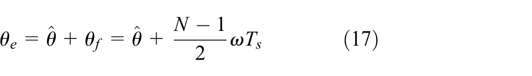
where
Simulation of BPMSM with speed sensorless
Mathematical model of BPMSM
There are two sets winding with different polar pairs embedded in the BPMSM: the torque winding (the number of pole pairs
The essence of the bearingless motor rotating part is the PMSM. With HF excitation, the model of the motor rotating part is shown in part 2. The model of the radial levitation force

where

where
Operation of BPMSM with speed sensorless
The system configuration diagram including speed control, levitation force control, rotor position, and speed detection based on the rotating HF injection method of the BPMSM sensorless vector control is presented in Figure 4. The traditional proportional–integral–derivative (PID) controller is adopted in control system. Some advanced control techniques,3,20 such as intelligent controller and nonlinear controller, will be attempted in the future work. The rotor field–oriented control strategy is used by
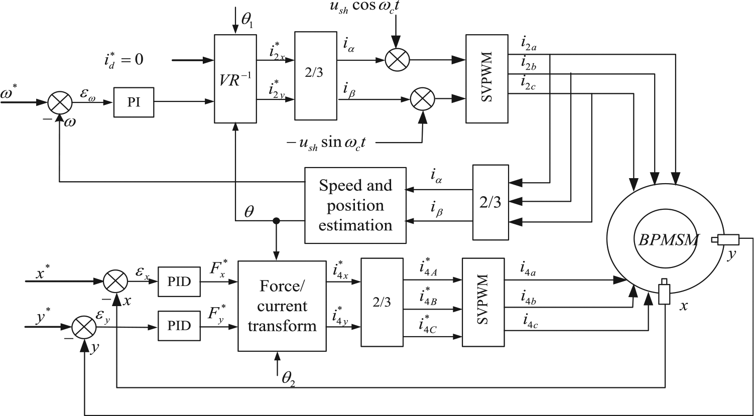
Configuration diagram of the controller system based on rotating high-frequency signal injection.
The simulation prototype parameters are as follows: the number of pole pairs of torque winding
In the system simulation, the variable-step method is adopted, and the simulation model is ode45. The frequency and amplitude of the HF signal are 1000 Hz and 5, respectively. The equiripple optimal approximation band-pass filter described in this article is used to extract the HF signal, and linear-phase compensation is adopted for the system estimated angle. The conventionally extended Kalman filter (EKF) algorithm is used to compare with the proposed approach. Detailed EKF algorithm information can be referred to Yu and Hu.
7
The parameters of EKF algorithm are as follows: state variable x, initial value of the state variable
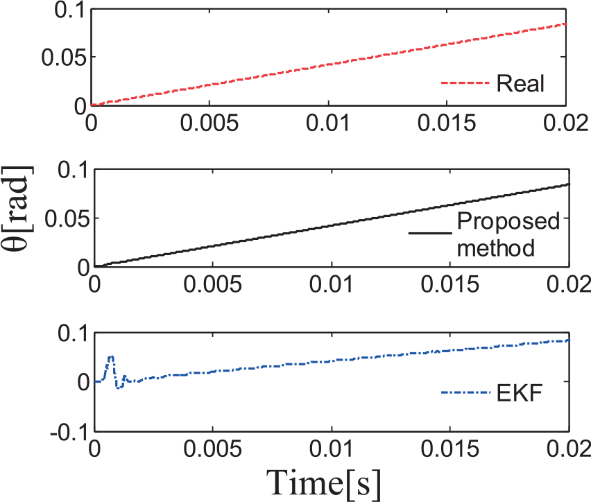
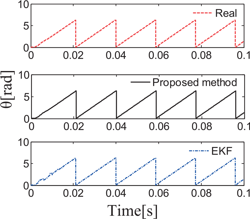
Figures 5–13 show the operational curves of speed sensorless based on the rotating HF signal injection method under the different rotating speed. Figures 5, 8, and 11 show the motor speed curve, while the speeds are 10 and 1000 rad/s, and mutated from 500 to 100 rad/s, respectively. Figures 6, 9, and 12 are the rotor angle position estimation curves. Figures 7, 10, and 13 are the rotor angle position estimation error curves. It can be seen that under the conditions of low-speed, high-speed, or speed mutation, the rotating HF signal injection method can accurately estimate the rotor position and speed in full scope of speed. Compared with extended Kalman filtering, the estimation performance at the low-speed and extremely low-speed ranges is superior. In addition, the track rotor speed using HF signal injection method is faster than using Kalman filtering with complex calculations.

Speed estimation at 10 rad/s.
Space position estimation at 10 rad/s.

Space position estimation error at 10 rad/s.

Speed estimation at 1000 rad/s.

Space position estimation at 1000 rad/s.

Space position estimation error at 1000 rad/s.

Speed estimation at speed step response.

Space position estimation at speed step response.
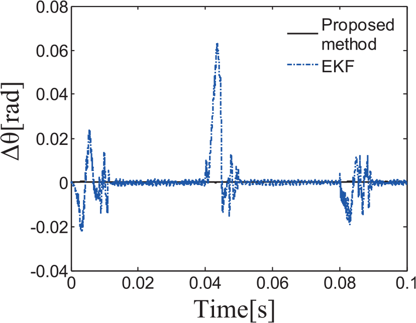
Space position estimation error at speed step response.
Figures 14–16 show the operation curves of speed sensorless when the motor cross, direct-axis inductance, and stator resistance each increases 20%, and the control parameters remain the same. Figure 14 shows the speed curve of a motor at 800 rad/s at parameter disturbance. Figure 15 shows the space position estimation error at parameter disturbance. Figure 16 shows the space position estimation error at parameter disturbance. It can be seen that the starting error of the EKF estimation is large when the system parameters change. Compared with EKF, the HF signal injection method is more robust during system parameter changes.

Speed estimation at parameter disturbance.
Space position estimation at parameter disturbance.
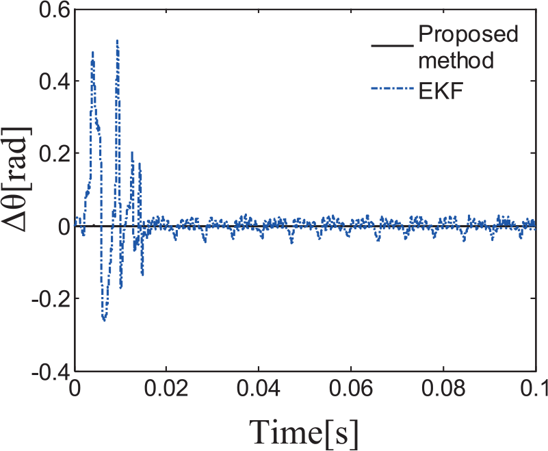
Space position estimation error at parameter disturbance.
Figure 17 shows the rotor displacement curves when the speed mutates from 100 to 20 rad/s and the rotor keeps stable suspension after adjustment.
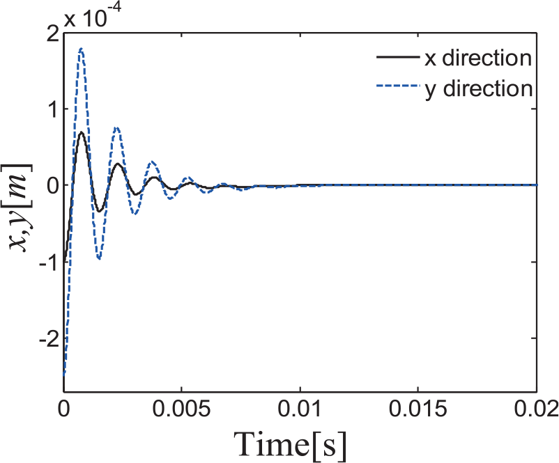
Rotor x and y displacements for speed step response.
Conclusion
This article proposes an improved rotating HF signal injection method based on an FIR-optimized filter in order to operate motors with speed sensorless. This method removes the synchronization filter unit to reduce the system complexity. An equiripple optimal approximation FIR filter is used to extract the HF current signal and ensure the error of the HF current signal is the smallest. The linear-phase compensation is added to ensure the delay of the motor rotor speed and position estimation is minimal. The speed sensorless vector control experimental platform of BPMSM is estimated for real-time simulation. The experimental results show that the proposed algorithm can accurately estimate the rotor speed and position in a full-speed range, and compared with Kalman filtering, the estimation precision is more accurate and robust.
Footnotes
Handling Editor: Chenguang Yang
Declaration of conflicting interests
The author(s) declared no potential conflicts of interest with respect to the research, authorship, and/or publication of this article.
Funding
The author(s) disclosed receipt of the following financial support for the research, authorship, and/or publication of this article: This work is supported by the National Natural Science Foundation of China (grant no. 61703186), Natural Science Foundation of Jiangsu Province (grant no. BK20150530), a Project Funded by the Priority Academic Program Development of Jiangsu Higher Education Institutions (PAPD), and the Professional Research Foundation for Advanced Talents of Jiangsu University (grant no. 14JDG077).