
Abstract
Considering space environmental requirements, a multidisciplinary optimization of a 2 degrees-of-freedom micro linear actuator is carried out to improve the overall performance of a nested flying vehicle in this article. To achieve high-quality microgravity environment, a nested flying vehicle is designed that can be operated inside the Space Station. The electromagnetic actuators are utilized to control the position and posture of the experiment device while the exterior structure is following the movement of the inner system. Each actuator is designed to generate vertical and horizontal forces at the same time. The actuator is composed of two permanent magnets, a 2 degrees-of-freedom coil on a printed circuit board and a steel back yoke. Due to the complexity of structure parameters modification, the geometry, the structural model, electromagnetism model, and multidisciplinary analysis process are integrated based on ModelCenter framework. In this case, the structural model is established using ANSYS/APDL. The electromagnetic analysis is performed by the magnetics postprocessing. The OPTLIB Gradient Optimizer, non-dominated sorting genetic algorithm II, and Design Explorer for multidisciplinary optimization with constraints are utilized for validation mutually. In view of the optimization results, compared with the prototype design based on experience, the width of the back yoke, the weight of actuator, and the residual force have been reduced by 23%, 50%, and 62% while the output forces resulted in an acceptable range.
Keywords
Introduction
Considering the requirements of some space science experiments, high-quality microgravity is needed to ensure the operation environment for experiments like the validation of fundamental physics principles, space fluid experiments, and non-Newtonian gravity experiments. However, space laboratory always provides a microgravity
Nowadays, additional design constraints need to be considered on both launch and space environment while ensuring the performance of the component. Space device designers also factor the reductions in the launch weight, volume, heat loss, and so on. These complicated requirements and constraints demand multi-objective and multidisciplinary consideration for the conceptual design of a space equipment design for microgravity sciences. Comparison of results provides for the magnitude of trade-offs, difficult to express before this work is accomplished. Most work on development of multi-objective optimization frameworks was carried out by Rao and Venkayya. 7 Multidisciplinary design, analysis and optimization (MDAO) is increasingly becoming a tool of importance in the overall design process of modern product design. MDAO is employed widely in modern complex system design.8–12 Analysis software such as MSC Patran/Nastran, ABAQUS, and Hypermesh could create finite element analysis (FEA) model and calculate the result in many engineering situations. MDAO’s significant contribution is primarily important to the conceptual design phase, 13 since the conceptual design phase is constrained by the requirements and all designed based on geometric models analyzing its properties. The conceptual design process is challenging even with high-powered computer resources and validated analysis software. 14 Furthermore, the single discipline design and analysis requires different tools, and the design needs to be developed from the system level. The multidisciplinary design and optimization (MDO) framework is one of the techniques of MDO, and it supplies an environment for tool integration, helping to build the workflows of the design and analysis process. This improves design quality and efficiency, and even enables the designer to obtain an optimum design within accuracy parameters and acceptable cost. Many of the current MDO frameworks are developed by corporations and academics with the requirement of manufacture. The software such as ModelCenter, iSight, and VisualDOC improve conceptual design quality and efficiency as an application of MDO frameworks.
The purpose of this work is to explore the possibility of using MDO frameworks for design components of space experiment. In this article, a conceptual design is proposed for precision control using smart actuator in novel nested flying vehicle (NFV) providing high-level microgravity environment. Section “Conceptual design of the electromagnetic actuator for NFV” presents the conceptual design of NFV and its critical components—the 2 degrees-of-freedom (DOF) electromagnetic actuator. In section “Multidisciplinary analysis of the placed actuators,” the multidisciplinary design and analysis (MDA) of the actuator is presented in detail, especially when fixed in the NFV under the microgravity environment. The ground experiment results of the prototype are shown that the simulation model is confirmed to provide the performance in high precision. Section “Multidisciplinary optimization of the actuator” shows the MDO integration process models of the actuator including those of electromagnetic analysis, structure estimation, and thermal analysis. The proposed approach is simulated through Modelcenter framework, and results are presented and discussed at the end of the article.
Conceptual design of the electromagnetic actuator for NFV
To achieve high-quality microgravity environment, a NFV is designed as shown in Figure 1 that can be operated inside the Space Station. Refer to the total acceleration in low-frequency range (<0.1 Hz) in the International Space Station (ISS),
1
the NFV can offer the space sciences a higher than

Schematic of a nested flying vehicle.
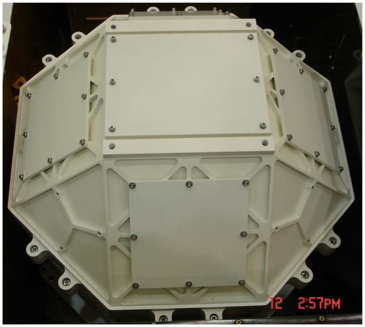
Prototype of the nested flying vehicle for launch.
The four electromagnetic actuators are distributed evenly on the inner system (Figure 3) and redundantly control the relative position of the inner structure and exterior follow-up structure as shown in Figure 1. Each actuator is designed to generate vertical and horizontal micro forces at the same time. The actuator is composed of two permanent magnets, a 2-DOF coil on a printed circuit board (PCB), and a steel back yoke as shown in Figure 4. Considering the installation space of the NFV and dimensions of the experiment device, the sharp size of the electromagnetic actuator should be limited. Hence, instead of a traditional wire-wound coil, a four-layer PCB is produced to reduce the thickness of coil assembly from 8 mm to less than 4 mm. One circuit board contains two mutually orthogonal sets of printed coils to provide 2-DOF exciting forces.

The location of four electromagnetic actuators between inner and exterior system.

3D illustration of electromagnetic actuator configuration.
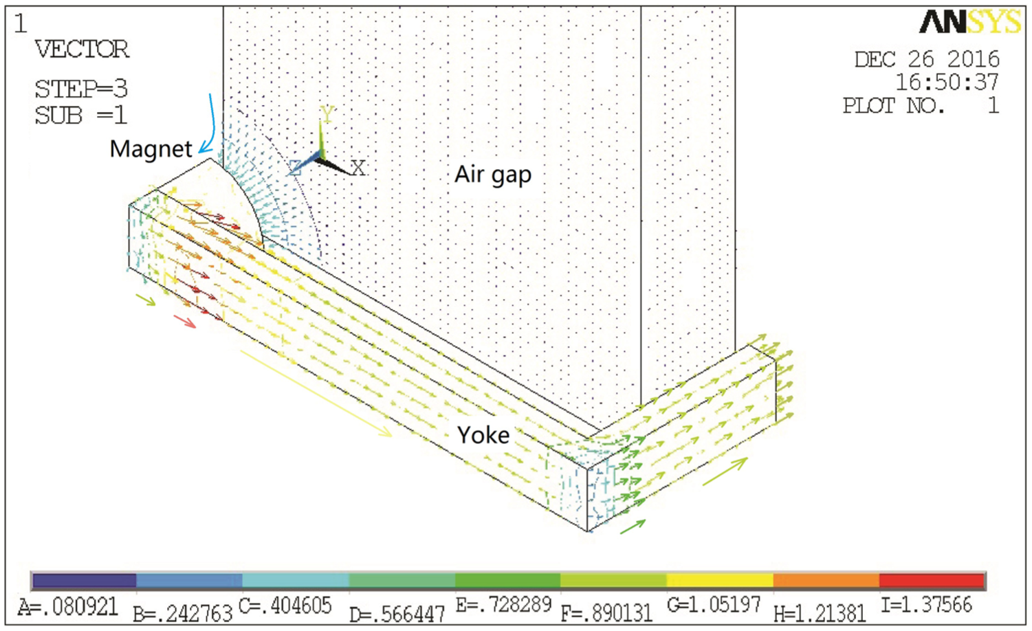
The current flow and the expected distribution of the magnetic lines of force are shown in Figure 5. The magnetic field produced by two permanent magnets placed on the both sides of a back yoke. The configuration of the back yoke for preserving the magnetic field of the permanent magnet is a closed-loop structure which may avoid excess leakage of magnetic flux into the experiment device. The back yoke made by permeable material is used for conducting the field lines. The analysis of finite element modeling (FEM) simulation shows that the magnetic flux density is almost constant within the boundary of the permanent magnets and back yoke in Figure 6.

Chart of the distribution of the magnetic lines of force.

Magnetic flux density in the designed component.
Flux distribution of the 1/8 electromagnetic actuator with 1/8 air between two magnets is shown in Figure 7. But an inhomogeneous magnetic field can be found as an hourglass shape between the two magnets. In the working area of the coil, the closer the coil is to the magnets, the stronger the magnetic field will be. According to the simulation result of single component solved by ANSYS, the designed yoke is not saturated. The configuration of four components model in Figure 8 shows the static magnetic solution which is most effective using the advantage of magnetic field counteraction. The arrows in the area give the direction of magnetic line. The results of the simulation shows that the magnetic flux leakage at the center of the inner system can be neglected as about
Flux distribution of the 1/8 electromagnetic actuator.

Static magnetic solution using four components model.
Multidisciplinary analysis of the placed actuators
Parameters of the actuator
As shown in Figure 4, a reference frame o-xyz is attached to the component at the center

Design variables for electromagnetic actuator: (a) back yoke, (b) coil, and (c) definition of racetrack current source.
In this case, a neodymium (NdFeB) magnet is selected which is the most widely used type of rare-earth magnet. Grade of the neodymium magnet is N50 in which the remanence Br=14.43 kGs, coercivity Hcb=12.24 kOe, intrinsic coercivity Hci=12.82 kOe, and energy product BHmax=48.34 MGOe. Assuming that the permanent magnet is set to the best working point with the maximum energy product, the magnetic flux density

Mathematical model
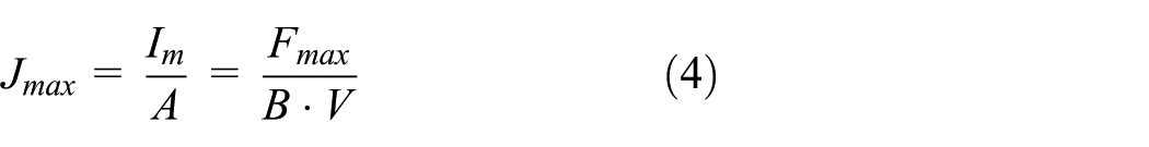
The flux density, the maximum current density in the coil, can be calculated using the normal formula for calculating the force acting on a current carrying conductor in a homogeneous magnetic field

where F, B, I, and l represent the force acting on the coil, the flux density, the current in the coil, and the length of the conductor. If B and I are vertical to each other, the direction of force can be decided by Fleming’s left-hand rule and equation (2) can be written as 17

where
where the

where
where
When the coil moves through the permanent magnetic field, a back induced voltage

where
Simulation results of the prototype
The 2-DOF electromagnetic actuator has been produced with the specifications of the experimental prototype given in Table 1. The stroke along x- and y-axis of the actuator
Specifications of the experimental prototype.

The parameters of the racetrack coil can be given by

Figure 10 shows the effect of perpendicular direction displacement on the force along the x-axis stroke while y-axis position of the coil is 15 mm. It indicates that the change of the output force along the stroke should be considered in the control strategy. And the amplitude of actuated force is reduced to about 50% when the coil located at the edges of workspace. The z-axis force is almost double in its numerical number which is undesirable design caused by nonlinear magnetic field at the edge. The coupling effect in the parallel system needs to be decoupled by dynamics modeling and corresponding control algorithm.

Force of the electromagnetic actuator for different displacement along z-axis: (a) x-axis force, (b) y-axis force, and (c) z-axis force.
The 2-DOF coil model is built up using COMSOL as shown in Figure 11. The distribution of voltage across the coil is shown in Figure 12 which generates driving force on the coil. The maximum current density in the coil including the air between the wires is about 13.15 A/mm2. Figure 13 illustrates the inductance distribution in the yz-plane of

2-DOF coil model built up using COMSOL.
The distribution of voltage across the coil: (a) front and (b) back.
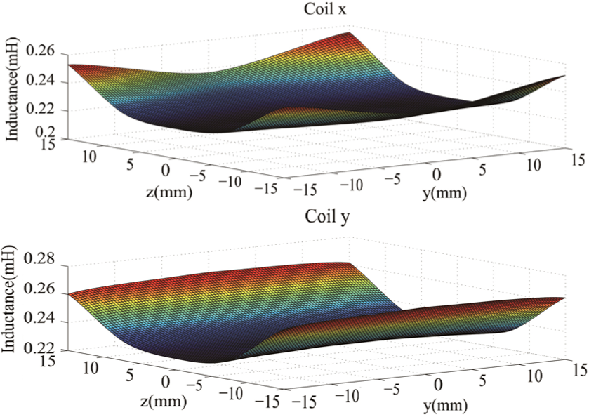
Inductance of the coils for different strokes.
Experimental results of the prototype
The experiment study simulates the microgravity condition in ground using suspension cables and a holder. And only 1-DOF translational output (force) and 1-DOF rotational output (moment) can be obtained at a single test. Hence, as shown in Figure 14, the four configurations of the ground test of the actuator can give 6-DOF outputs, including three forces and moments in the three orthogonal directions.

Ground experiment study of the electromagnetic actuator: (a) x-axis translation and y-axis rotation, (b) y-axis translation and z-axis rotation, (c) z-axis translation and y-axis rotation, and (d) y-axis translation and x-axis rotation.
Figure 15 shows the test result of actuator characteristic at the center of the workspace. It indicates that the data of quasi-static force measurements follow the linear Lorentz force relationship, for different current and actuating directions. Since the design is focused on the smaller output actuator in which the magnitude is about several hundreds of
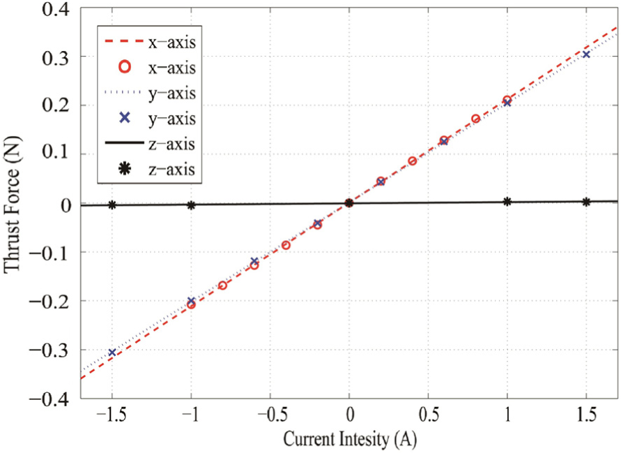
Output force for different input current.
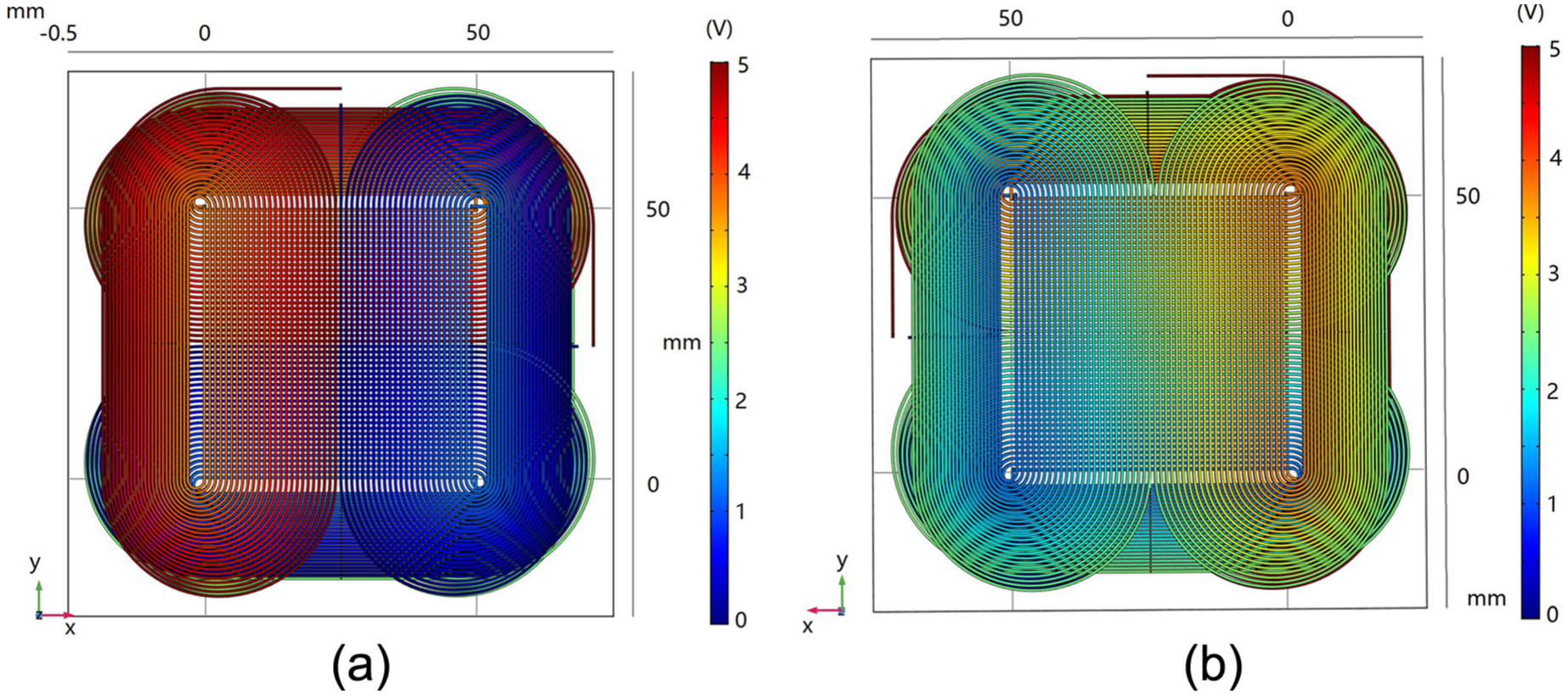
Comparing the test and simulation results in a reasonably close operation condition as shown in Figure 16. Figure 16(a) shows the x-axis force is uniformly distributed in the test work plane. But in Figure 16(b), the undesirable force along z-axis is not evenly distributed. As show in Figure 16(c) and (d), the driving force errors between the test results and simulation results are less than 10%. Hence, the analysis model is confirmed to provide the electromagnetic performance by simulation in high precision which can be utilized to optimize the structure parameters of the designed actuator.

Comparison of the test result and simulation result in a reasonably close operation condition: (a) test result and simulation result of
Multidisciplinary optimization of the actuator
In our previous works on optimization of the four electromagnetic actuators around inner system, we found that multi-objective optimization for single discipline always lead to degradation in performance of other disciplines. For example, the

where Fx, Fy, and Fz and represent the x-, y-, and z-axis and component of the exciting force,
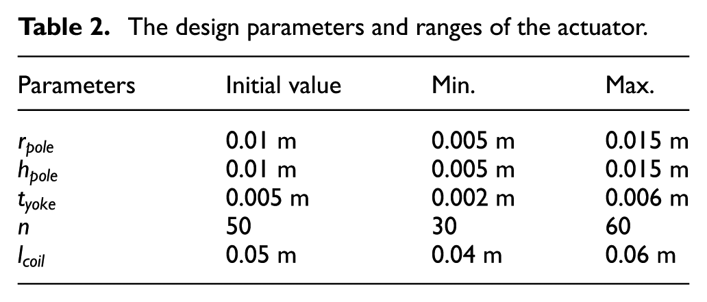
The design parameters and ranges of the actuator.
The design structure matrix
One of the most useful tools in developing an integrated process is the annotated design structure matrix (DSM). 19 A DSM for the designed actuator system is shown in Figure 17. The six components and the cords of attachment shown in the DSM represent the relationship and dataflow diagram of the system integration process. The coupling between modules is represented by a database icon which shows the data communicated from module-to module. The components in the process are described in more detail below:
Geometry. The geometry module is responsible for maintaining a parametric geometry model of the actuator being analyzed and for updating that model as system-level design variables are changed. The geometric calculating process is carried out in ModelCenter mainly calculating the geometric parameter with system-level design variables. This module outputs the outer mold line of model to support operational settings, structural establishment, and electromagnetic analysis. Meanwhile, the geometrical parameters are exported to thermal analysis and integrated computation.
Operation. The operation module is responsible for providing the on-orbit operational constraints for updating the configurations of the external conditions generated by on-orbit environment. The module is affected by the outer mold line of the geometry model. The outputs are the load cases for structural module and some operational profile for electromagnetic and thermal analysis. The constraints are collected by ModelCenter to automatically filtrate the parameters for the next step of the optimization.
Structural. The structural module is responsible for determining the structural sizing required for the actuator to support sufficient force to withstand the load conditions imposed during operation. This is a complex effort and involves modeling, meshing, and analysis. The main outputs from the structural module are structural weight and FEM mesh. The ANSYS was selected as the modeling and analyzing tool in this article.
Electromagnetism. Once the outer mold line and FEM mesh are generated in the previous module, the electromagnetism module performs a simulation and optimization of actuator to output the virtual work forces by calculations on element components. The modeling process and magnetics postprocessing is done in Mechanical APDL with the .mac file and invoked by ModelCenter. The selection of magnet is based on experience.
Thermal. Once the outer mold line of actuator is defined by geometry module, the thermal module enables computation of the temperature of internal environment purposed to be minimal. The temperature is computed by experience formula.
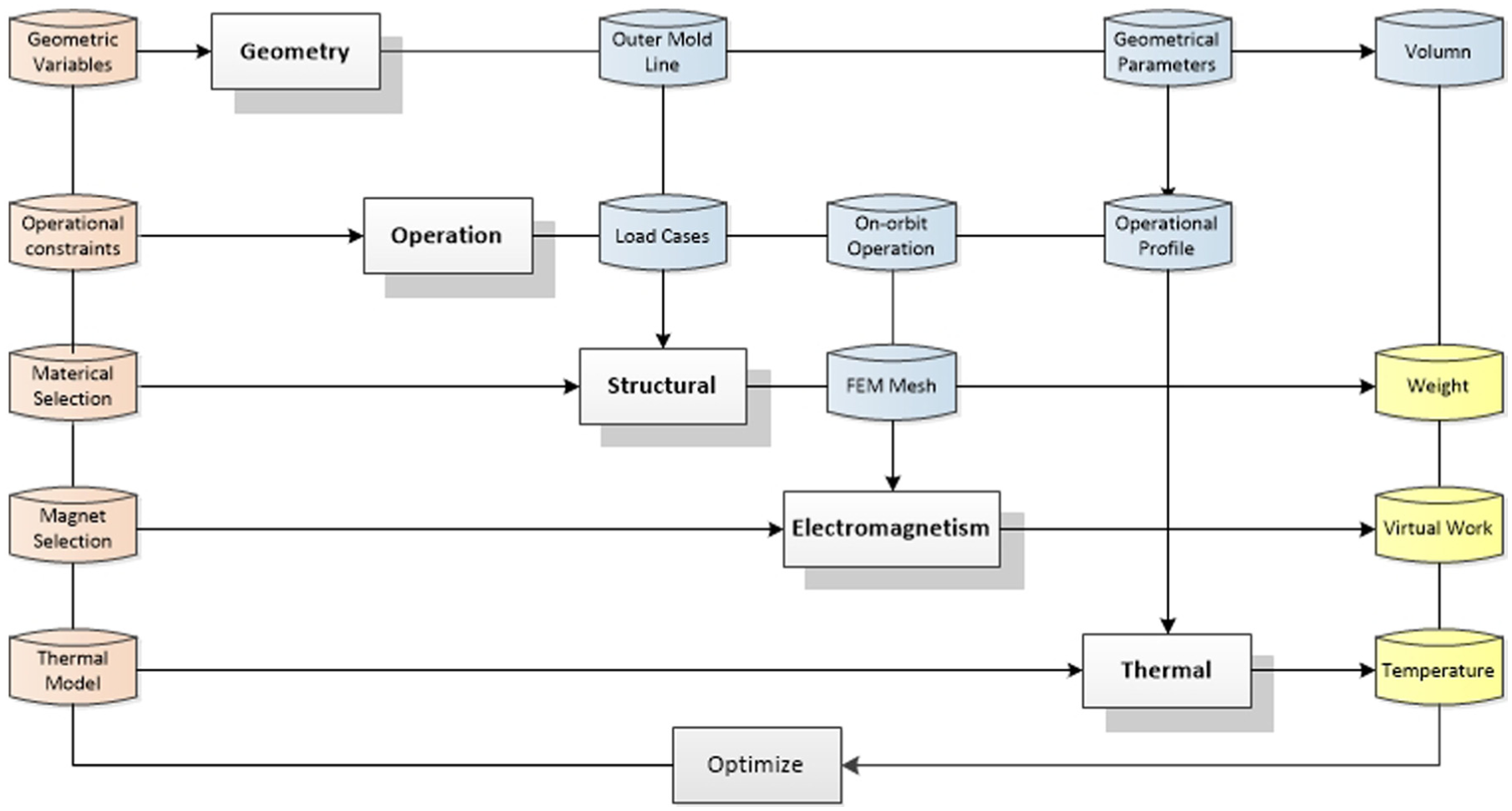
Structural design, multidisciplinary analysis, and optimization process.
Analysis and optimization
The analysis process for actuator based on DSM is built in ModelCenter framework which makes modeling, analyzing, and optimization more convenient and efficient. ModelCenter is a powerful tool for automating and integrating design codes. Once a model is constructed, trade studies such as parametric studies, optimization studies, and design of experiments (DOE) studies may be performed. In this work, there are three types of analysis executed in software:
Single point analysis. The simple one-shot run through ModelCenter is to evaluate the experience design and validate the optimization results.
Parametric trade study. This mode is used to study the basic tendency of object in design space. The DOE of ModelCenter helps to define ranges for design variables and loop over the defined ranges, evaluating each design in turn.
Optimization. In this mode, the design variables are defined, along with their range. Overall object are also defined, along with constraints. The optimization is done using different algorithms through ModelCenter.
Implementation
In this article, the ANSYS module of mechanical and EMAG are employed to analyze and simulate for structure and electromagnetism due to its macro function. The automating, integrating, and optimization techniques of ModelCenter help to implement the whole design and optimization.
Besides the main function of modeling and analyzing of ANSYS, macro helps record the entire manipulation. The software could import the .mac file run manipulations step by step. The file is normalized so that users can also modify the key parameter and run the macro quickly. Hence, the parameters such as boundary conditions and pressure conditions defined on the structure can be automatically loaded into the software. The computational mesh required by each discipline can be changed at each design cycle by updating the macro. The ModelCenter supplies many utilities for creating new software component and FileWrapper is used. 20 Then, users could define input file with macro file so that ModelCenter is able to update the inputs of model and drive a pre-processor of the method to automatically generate a mesh for the modeling of the new configuration in each iteration.
Figure 18 illustrates the analyzing workflow in the ModelCenter. The outer loop is for optimizing using optimization tool which is a collection of optimization algorithms that can be used within ModelCenter. There are over 30 algorithms available including gradient-based optimizers, genetic algorithms, multi-objective algorithms, and other heuristic search methods. The analysis and simulation are proceeded in four position of actuator after sifted from eight corners. The location at the largest virtual force in z-axis is the computing target for single iteration. ModelCenter supplies a graphical flowchart–like process model that explicitly tells what order to run each component, and parallel helps to run component concurrently. Therefore, the four analyses could run in the same time. Two analyses for one position are to compute both the result and systematic error. It takes 50 s in average to complete a analysis for one position on a workstation with two 2.00 GHz processors and 64 GB of memory.
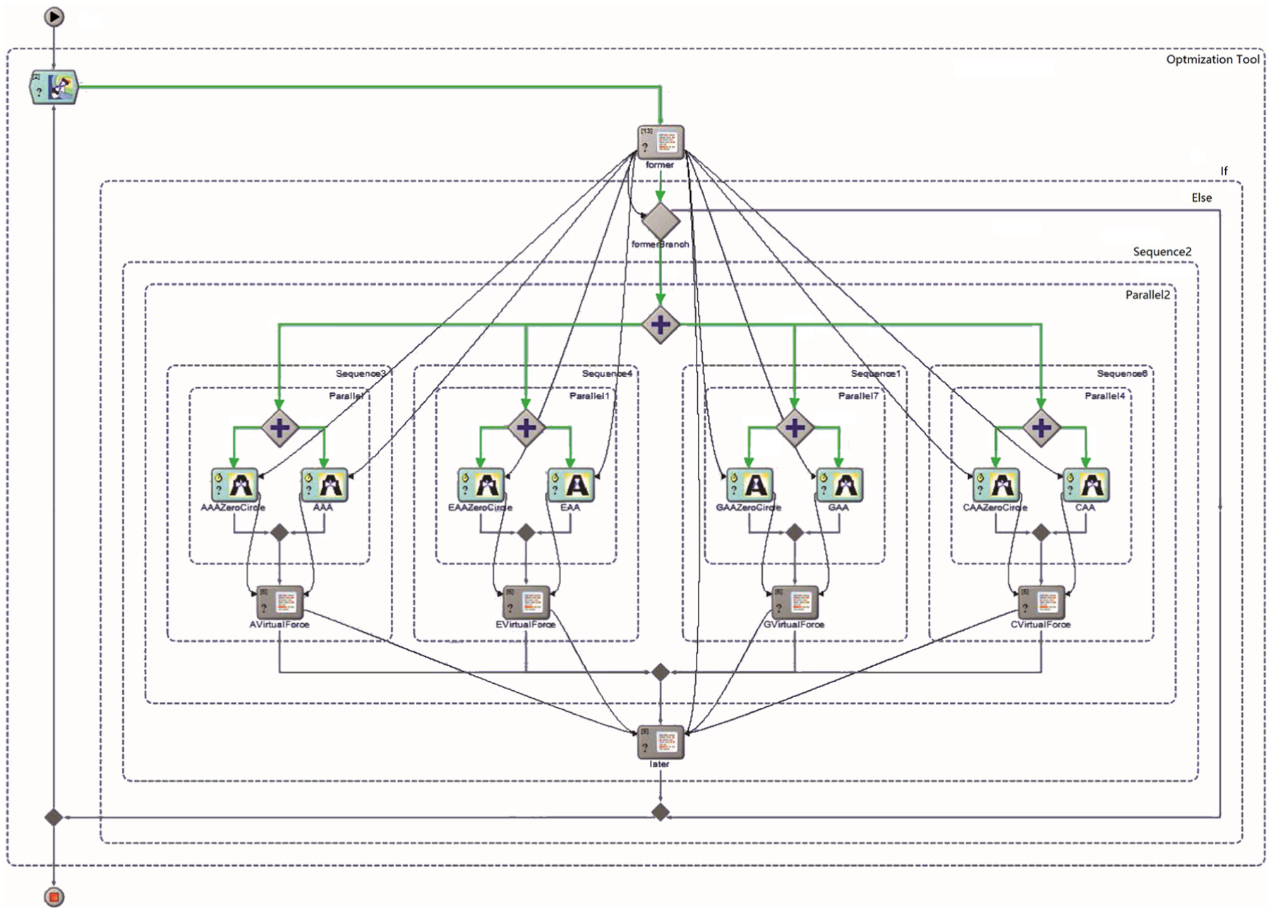
The flow chart for the multi-objective optimization case.
The optimization of actuator is a multi-objective problem with constraints. For the purpose of validating, OPTLIB Gradient Optimizer, NSGA II (non-dominated sorting genetic algorithm II), and Design Explorer integrated in ModelCenter are used. Gradient optimizer uses a sequential quadratic programming (SQP) algorithm 21 to solve constrained optimization problems. Design Explorer is a powerful tool developed by Boeing for design space exploration and optimization. And its main technique is surrogate-based optimization which is viable method for expensive computer analysis22,23 also tried to optimize the actuator but the consumption of time is unacceptable.
Results
The simulation and analysis for actuator are computationally expensive processes, while the optimization is an iterative process, which usually invokes the analysis models for more than thousands of times using traditional algorithm. Thus, it is quite time-consuming to implement multidisciplinary design optimization. The Darwin with common genetic algorithm failed to converge and lasts more than 10 days. While OPTLIB Gradient Optimizer, NSGA II, and Design Explorer converged and got the optimal results. The weighting method is disposed when using the SQP and Design Explorer in order to convert the multiple objects. The NSGA II parameters are set for the optimization run: Population Size=48, CrossoverProbability=0.7, EtaC=15, EtaM=20, MutationProbability=0.5; Stopping Criterion: ConvergenceGenerations=5, ConvergenceThreshold=0.001, MaxGenerations=100, MaxEvaluation=1000. Avoiding the local convergency of SQP, some trials of initial design are disposed. The NSGA II resulted in 163 Pareto frontier points, and the final result was chosen according to some disciplines.
The analysis result of experience violated the constraint, while other algorithms converged and got accepted result. All the results gave out the best design of actuator following the optimization problem and showed a better performance in these disciplines. The process of NSGA II costs more than a day because of the traditional global search. SQP converged in a shorter time, but the trials of initial design cost more. The use of systematic and efficient samples and surrogate models helps to solve the expensive and non-smooth optimization problem. Design Explorer leads to an optimal result with a moderate time consumption. Because of the fewer changes of
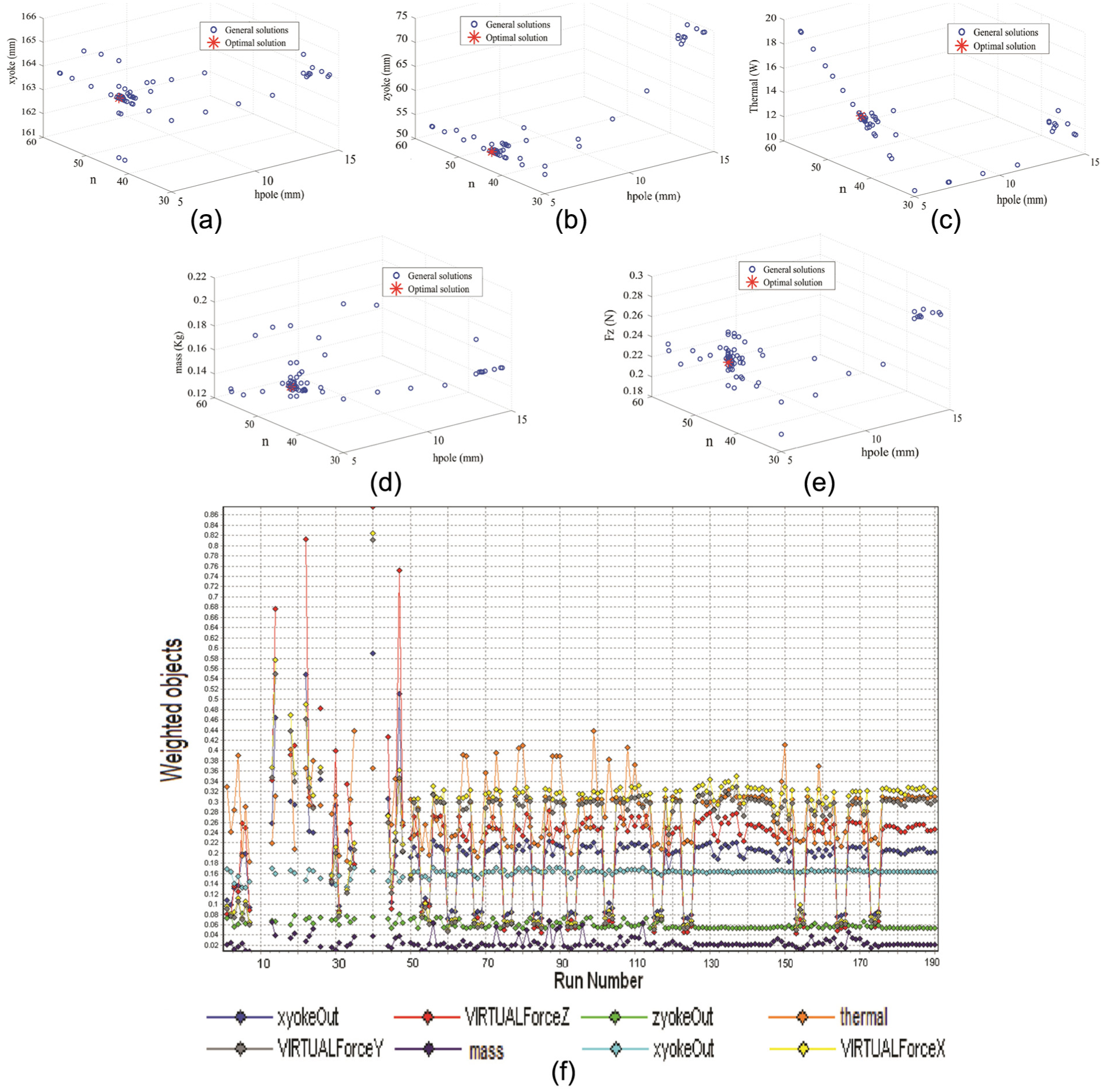
Selected points of the interaction: (a)
Table 3 shows the optimization results of three algorithms compared with the design based on experience. In view of the optimization results as shown in Table 3, the optimized actuator shows a better performance in structure. So it can be concluded that the parametric design and multi-objective optimization approach and process with ModelCenter in this article are proper and practical. In view of the optimization results, the width of the back yoke, the weight of actuator, and the residual force has been reduced by 23%, 50%, and 62% while keeping the output forces satisfying constrained conditions. Based on the optimization, the entire performance of actuator is improved significantly.
Optimal results of the electromagnetic actuator.

NSGA II: non-dominated sorting genetic algorithm II; SQP: sequential quadratic programming.
Conclusion and further work
An MDO is performed for the FEA model of a 2-DOF electromagnetic actuator which is designed as the main driving component in a novel space NFV. The ANSYS/APDL is chosen as the design and analysis tools. The prototype of the actuator has been tested, and the experiment results have shown that the analysis model can provide the electromagnetic performance by simulation in high precision. The printer command language (PCL) code helps execute the command of design and analysis process automatically. The design and analysis workflow was established with components in ModelCenter framework. Moreover, the linking for data transportation, integration interfaces, and optimizer were supplied by ModelCenter. The OPTLIB Gradient Optimizer, NSGA II, and Design Explorer were adopted to optimize the structure. Compared with the prototype design based on experience, the width of the back yoke, the weight of actuator, and the residual force has been reduced by 23%, 50%, and 62% while the output forces resulted in an acceptable range. The design, analysis models and algorithms can be integrated together in ModelCenter, which makes design and optimization more efficient.
The MDO approaches and process using ModelCenter proposed in this article is feasible and reasonable, which can enhance the actuator performance and reduce the complexity of operation simultaneously. This investigation allows the designer to use and expand MDO frameworks for design complex equipments of space experiment. In the future work, the magnetic flux density analysis of the actuator design and mechanism analysis will be additional proposed to optimize using MDO frameworks. In advanced, some new-style of optimal algorithms, especially efficient algorithm using surrogate model for computational analysis, toolboxes will be further studied to improve the design capacity of intelligent space devices for microgravity science experiments.
Footnotes
Handling Editor: Jiin-Yuh Jang
Declaration of conflicting interests
The author(s) declared no potential conflicts of interest with respect to the research, authorship, and/or publication of this article.
Funding
The author(s) disclosed receipt of the following financial support for the research, authorship, and/or publication of this article: This study was supported by Youth Innovation Promotion Association Foundation of CAS 2017-2020 (no. 2017191), Qianlong Fellowship Program 2016-2018 of CSU, and the subproject “Concurrent design, synthesis simulation and verification system” of a National Science and Technology Major Project.