
Abstract
A new type of walking mechanism for middle- and low-speed maglev vehicle, including a single anti-roll beam placed at the middle of each suspension frame, a big air spring placed at the middle of each longitudinal beam of each suspension module, and a forced steering mechanism canceled, was proposed to improve the comprehensive competitiveness of the middle- and low-speed maglev vehicle in the field of urban rail transit. The dynamic characteristics of a new-type maglev vehicle were investigated by dynamics simulation analysis. The following conclusions are drawn based on the obtained results: the new-type maglev vehicle meets the operational requirements at the running speed of 160 km/h on the straight line and at the running speed of 30 km/h on the curved track of radius 75 m.
Introduction
Maglev train is lifted from the roadway or track beam by a magnetic field. The vehicle does not burn fuel and does not need engines. It is suspended beneath the track beam by attracting electromagnetic force and is driven by linear electromotor. It has better characteristics than conventional transports, including higher speed, lower noise, easier maintenance, and more safety. 1 As a new kind of transportation facility, maglev train is very popular in the area of urban transit.
There are two basic types of maglev vehicle: electromagnetic suspension (EMS) and electro-dynamic suspension (EDS). Although a major advantage of the EDS is naturally stable, the production process of magnetic materials in EDS system is more complex and expensive. Therefore, EMS is the most commonly used type. The representations of EMS series maglev vehicle are high-speed TR (transrapid) series of Germany and low-speed high speed surface transportation (HSST) series of Japan. 2 In addition, the maglev vehicles adopted the walking mechanisms of the HSST series low-speed maglev train are most widely used in the field of middle- and low-speed maglev train, such as South Korea, China Changsha maglev vehicle.
As is well known, the maglev force is inherently unstable, which leads to the dynamic characteristics performing diversity and complexity, so how to keep levitation system steady becomes more difficult. This problem must be urgently addressed. Generally, there are two ways to perform the research of the maglev vehicle, one of the ways is to focus on the controller design and another way is to focus on the dynamics characteristics of the maglev vehicle structure.
Fortunately, recent years, many researches on levitation stability have been carried out and some progresses have been greatly achieved in terms of levitation stability of the maglev vehicle. The paper 3 pointed out that levitation stability quite depends on the performance of the levitation controller while a maglev vehicle is moving at low speeds or standing still. Considering the time delay and parametric uncertainties, Reza et al. 4 researched the levitation stability with external disturbance, using adaptive robust controller. According to a full-state-feedback controller, H Wang et al. 5 realized its levitation stability on an elastic track beam by utilizing a single magnet levitation system as the object. Cai and Chen 6 researched the levitation stability of the maglev system, adopting the active and semi-active control law. Currently, levitation controller designs of the maglev vehicles have made remarkable achievements, especially in the field of dynamics studies of maglev vehicle. A model of the track beam was founded by Lee et al., 7 with the model superposition method, demonstrating the influence of system parameters on the levitation stability for maglev vehicle. Kim et al. 8 further investigated the levitation stability of an EMS-type maglev vehicle based on a virtual prototyping integrated 3D full vehicle model while moving at low speed or standing still. YQ Deng et al. 9 established a multi-body system dynamics model using SIMPACK software and verified the feasibility of the modeling method via the test. XY Ye et al. 10 set up a 76 degrees of freedom model of a maglev vehicle and optimized the parameters of the vehicle steering mechanism. WM Zhai and CF Zhao 11 not only built a low-speed maglev dynamics model, but also analyzed the dynamics characteristics of the elastic bridge and levitation control system. The dynamic characteristics were studied by JS Lee et al. 7 and JD Yau, 12 when the maglev vehicle was running on a elastic bridge at different velocities. But as discussed above, whether the studies of the levitation controller design or the dynamics analysis of the maglev vehicles are based on the traditional walking mechanisms of the HSST-type maglev vehicle, there are still some shortages of the walking mechanism of the HSST-type maglev vehicle. For example, four secondary air springs are installed at end of each longitudinal beam as shown in Figure 1, which is not conductive to decoupling control among the suspension frames. The maximum velocity of the HSST-type maglev vehicle is same as the speed of the subway and light rail train approximating 100 km/h, so it is hardly possible to find out where market orientation is. As a result, a new type of walking mechanism is devised to further prompt the extension of the middle- and low-speed maglev vehicle and accelerate the commercialized development of the middle- and low-speed maglev vehicle.

HSST-type maglev vehicle.
New-type walking mechanism design
The design of the single lateral anti-roll beam
As the name implies, the main function of the lateral anti-roll beam is to prevent the lateral rolling of the car body when the vehicle runs on the curve. Meanwhile, it can let the vehicle adapt to a greater line distortion. Traditional HSST series maglev vehicles are adopted the double lateral anti-roll beam before and after ends of the maglev frame, as shown in Figure 1. Differently, the new type of walking mechanism is adopted a single lateral anti-roll beam at the middle of the levitation frame, as shown in Figure 2. The functions and connection relation of the lateral anti-roll of the new-type maglev vehicle are same as the the functions and connection relation of the lateral anti-roll of the HSST-type maglev vehicle.

New-type maglev vehicle.
The design of levitation frame decoupling and the linear bearing
Each levitation frame of the traditional HSST series maglev vehicle not only is coupled with each other, but also is connected by sliding table, as shown in Figure 3. Meanwhile, since the air springs are installed upside down with the smaller sizes, their recovery abilities are a little weak. As a result, it is necessary to adopt a forced steering mechanism to enhance the curve negotiation capacity, when the vehicle runs over a smaller curve track. In addition, the structure disposal of the HSST series walking mechanism is not conductive to control among the levitation frames. Once one of the modules generates abnormal movement, it will directly affect the movement of other modules. Thus, the capacity of the curve negotiation will also be affected directly. Differently, the walking mechanism of new-type maglev train consists of three levitation frame modules, as shown in Figure 4. Obviously, the levitation frames are independent of each other. In addition, the hinge joint between the middle sliding table set up on the longitudinal beam and car body utilizes the linear bearing in the new-type maglev vehicle, as shown in Figure 4. Adopting the linear bearing can not only release the lateral degrees of freedom, but also realize the decoupling control between the car body and the levitation frame.

HSST-type suspension frame.

New-type suspension frame.
Furthermore, because the support air springs are installed on the positive direction with bigger sizes and stiffness, the air springs can produce a large recovering force when the vehicle runs over the curved track. Due to the large recovering force, even though the auxiliary guiding device is canceled, the vehicle can also stably pass through the small radius curve track. Therefore, the walking mechanism structure can be simplified and the weight can be reduced to a certain extent in the new-type maglev vehicle.
The design of the long linear motor
Because the linear motor is the only traction power source for the maglev vehicle, its traction characteristics is very important. However, some external factors, such as track irregularity, external disturbance, can lead to the change of the distance between the motor stator and rotor. The change will worsen the traction characteristics, which is not helpful to further improve the running speed of the maglev vehicle. Therefore, the distance between the motor stator and the motor rotor should not be too short. Conversely, it should be long.
Generally, because of the motor end effect, the efficiency of the motor is about 0.75, and power factor is about 0.55. Both of them are small so that it is urgently necessary to reduce the end effect of the motor for a higher running speed of the middle- and low-speed maglev vehicle. Therefore, for a better dynamic characteristic of the new-type maglev vehicle, the distance among the adjacent traction motors of the new-type maglev vehicle has been reduced to 0.08 m (the distance of traction linear motor is 0.98 m in the HSST-type maglev vehicle). Thus, the 0.08 m gets close to the value of one-third of the motor pole pitch, which caused the reduction in the end effect on the adjacent motor by a large margin and improved the traction characteristics of the motor to a large extent in the new-type maglev vehicle.
In addition, due to the air springs set up at the middle of the longitudinal beam in the new type of maglev vehicle, the maximum length of the motor is only limited by the module length. Dissimilarly, for the reason of the air springs installed on the ends of each levitation frame in the traditional HSST series maglev vehicle, the maximum length of the motor is limited by the distance between the two air springs on the same side. Hence, the maximum length of the new-type motor can be 2.8 m, the value of which is same as the length of module.
Through the above analysis, it is obvious that the length of the traction motor of the new-type maglev vehicle is longer compared with the length of the traction motor of the HSST-type maglev vehicle. Meanwhile, the traction motor has a smaller end effect in the new-type maglev vehicle, compared with the traditional traction motor in the HSST-type maglev vehicle. Therefore, the former possesses a better traction characteristic. The traction characteristics of two kinds of traction motors are shown in Figure 5.

Motor traction characteristics.
The design of levitation controller
The model with a real levitation controller is the best to simulate the dynamic characteristics of the maglev vehicle. 13 In the early stage of the dynamics characteristics researches of the maglev vehicle, the electromagnetic levitation force is usually equivalent to the spring-damping force, such as the paper.14,15 The method taking the spring-damping force as the electromagnetic levitation force is the passive control for the maglev vehicle. However, whether the electromagnetic levitation force is controlled actively, different effects about levitation stability and dynamic response characteristics of the maglev vehicle will come into being. 16 The Proportion- Integration-Differentiation (PID) controller that actively controls the levitation force is a real levitation controller. Hence, it is taken as the levitation controller as shown in formula (1)

where K2, K1, and K3 are the feedback coefficients of levitation gap, the velocity of levitation gap, and the vibration acceleration of the levitation electromagnet, respectively.
Dynamics model
Vehicle model
In practice, the model structure of the maglev vehicle should be rationally simplified and resembled for a better dynamic analysis. That is the important parts of the vehicle structure should be reasonably considered and the other parts that essentially meaningless can be ignored to a certain extent. Though the analysis of the key problems about the new-type maglev vehicle, the relations of each component are as follows:
Since the electromagnets at bottom of the levitation frames are fixed on the levitation modules, there are no independent degrees of freedom among them. Moreover, a single levitation frame has 6 degrees of freedom, including longitudinal motion, up-and-down motion, lateral motion, horizontal rotation, pitching motion, and yaw motion.
The single anti-roll beam connected with the levitation modules possesses slightly yaw motion relative to levitation modules. Additionally, there is a relatively lateral swing between the hanger rods of the anti-roll beam, and each of the hanger rods is connected with the left and right sides of the anti-roll beams.
Since the sliding tables of modules 1 and 3 are absolutely fixed with car body, there are no degrees of freedom between the sliding tables and car body. Each of the hanger rods has a pitching motion relative to car body. Just like the traditional HSST series maglev vehicle, the car body and single levitation frame of the new-type maglev vehicle also have 6 degrees of freedom, respectively.
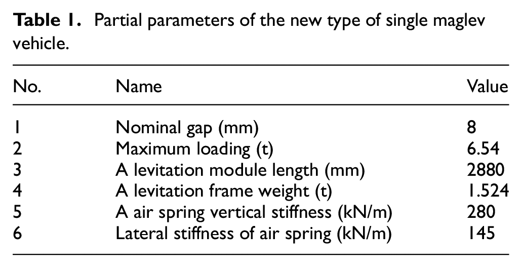
By analyzing the link of each component, there are 56 degrees of freedom in the new type of single maglev vehicle with three levitation modules and it is established by the SIMPACK software to conduct the research for the dynamic characteristics analysis. The dynamics model of the new-type maglev vehicle is shown in Figure 6. Partial parameters of the dynamics model are shown in Table 1.

Dynamics model of the new-type maglev vehicle.
Partial parameters of the new type of single maglev vehicle.
Track beam irregularity model
As is well known, maglev line irregularity is the main excitation for the maglev vehicle, 13 so it is significant and necessary to select a reasonable track spectrum for the dynamics simulation. At the early stages, the railway rail spectrum is often adopted as the line irregularity of maglev vehicle for the dynamics simulation. Unfortunately, it is not reasonably to adopt the high-speed railway rail spectrum as the maglev line track spectrum. 13 Therefore, the paper 17 studied the dynamic characteristics of the real maglev line based on the grade power spectral function. Nevertheless, due to the absence of a unified formula, it is difficult to achieve the reasonable grade power spectral function. Fortunately, comparing the real measurement value with theoretical value, the paper 18 proved that the unified analysis formula of the maglev line power spectra proposed by China Academy of Railway Sciences is better in line with the actual line spectrum. The unified analysis formula of the power spectrum is shown in Formula (2)

Here, f is the spatial frequency, and the unit is m−1. A, B, C, D, E, F, and G represent the parameters of the maglev track characteristics. Since the track beam line irregularity in Tangshan can better simulate the dynamic characteristics of track beam line irregularity to a much greater extent in the field of the middle- and low-speed maglev vehicle, it is regarded as the outside line irregularity excitation in this article. The lateral and vertical track line irregularity can be acquired according to formula (2) since the paper 18 provides the parameter values of the maglev track characteristics in Tangshan. As a result, though correlation calculation, the lateral and vertical track irregularities can be acquired, as shown in Figures 7 and 8, respectively.

The lateral irregularity of the track.

The vertical irregularity of the track.
The numerical simulation of the new type of maglev train
For validating the reasonability and superiority of the new type of maglev vehicle, the research for the dynamic characteristics of the new type of maglev vehicle is developed by dynamics simulation using the SIMPACK software. Assuming that when the new-type maglev train runs over the steel composite beam, the track beam is regarded as a rigid body and the irregularity of track beam is taken as the outside turbulence. Unless otherwise mentioned, all of the track irregularities are adopted as shown in Figures 7 and 8. Besides, to identify with actual situation of the vehicle operation, assuming that the initial levitation position of the levitation electromagnet and the track beam is 16 mm apart, static equilibrium position of the levitation gap is 8 mm all the time, and the speeds of the vehicle are 110 and 160 km/h with full load, respectively. The reason for choosing the two kinds of speeds is that the actual maximum operating speeding is 110 km/h with regard to EMS-type maglev vehicle. According to the improvement of the motor and walking mechanism, the higher speed is possible. Meanwhile, the curve negotiation characteristics of the new-type maglev vehicle are also vitally important on the small radius curve. So, it is studying the dynamics characteristic of the new-type maglev vehicle that is imperative in those cases. It is worth noting that the levitation modules are symmetric from the left and the right, so only the levitation modules at the right side are taken as the research objects with no any special instruction in this article.
The dynamics simulation analysis on the straight line
Since the levitation stability of the maglev vehicle is a significant problem and the operation foundation of the maglev vehicle, it is necessary to investigate the stability of the levitation gap which is shown in Figure 9.

Levitation gap dynamics response.
Through the analysis in Figure 9, with an overshoot amount of levitation gap less than 2%, it is clear that the maglev system can achieve stable levitation after 0.5 s. And the maximum deviation of the levitation gap is less than 2 mm when the vehicle acquires stable levitation. Because the floating process is included in the simulation process, it can be concluded that the levitation system has a better dynamic response characteristics at the speed of 110 and 160 km/h, which meets the acquirement of levitation stability performance.
When the vehicle gets to stable levitation, the ride quality will be a crucial issue that is closely related to the vibration acceleration of car body. Therefore, carrying out the research for the lateral and vertical vibration acceleration of car body should be addressed, which are shown in Figures 10 and 11, respectively.
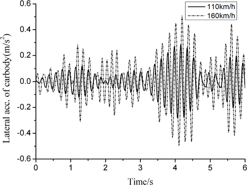
Lateral vibration acceleration of car body dynamics response.

Vertical vibration acceleration of car body dynamics response.
From Figure 10, it is obvious that the lateral vibration acceleration of car body is less than 0.6 m/s2 for both of the velocity, which meets the requirements less than 1 m/s2. 19 As shown in Figure 11, when the levitation system is stabilized, the vertical vibration acceleration of car body is less than 0.5 m/s2, which meets the requirements of the upward vertical vibration acceleration less than 0.5 m/s2 and the downward vibration acceleration less than 1 m/s2. And the value is also in line with the urban tracked air-cushion vehicle (UTACV) quality that the maximum vertical vibration acceleration of car body must be less than 0.05g 19 (g is the gravitation coefficient). In addition, the evaluation criteria of the maglev vehicle dynamics performances usually adopt the evaluation standard of railway vehicle dynamic performance, such as ISO2631, UIC513, DIN4567-2-2, GB5595-1-985. It means that there is no specialized evaluation standard for maglev vehicle system dynamic performances in the field of middle- and low-speed maglev vehicle. Consequently, for a better development of the railway industry in the world, the ISO2631 is adopted as the evaluation standard of dynamic performances for the new-type maglev vehicle, and it is shown in Table 2. The ISO2631 has been developed a standard by the International Standards organization. The ISO2631 is used for assessing and reducing the size of vibration related to the human body, whatever mode of transport. The running quality of maglev vehicle also is evaluated by the standard. Though the analysis of the vehicle stability index according to the ISO2631, the lateral and vertical stability indexes of the vehicle are 1.468 and 1.816 at the speed of 110 km/h, respectively. The lateral and vertical stability indexes of the vehicle are 1.742 and 2.296 at the speed of 160 km/h, respectively. It can be known that when the vehicle runs at the two kinds of speeds, the lateral and vertical stability indexes of the vehicle satisfy the standard of the excellent grades shown in Table 2.
The vehicle stability index ranking.

The change of levitation gap will lead to the changes of levitation force and levitation current so that the maglev vehicle can achieve a better stable levitation around the nominal levitation gap. So, it is necessary to study the dynamics characteristics of the levitation force and levitation current that are shown in Figures 12 and 13.

Levitation force dynamics response.
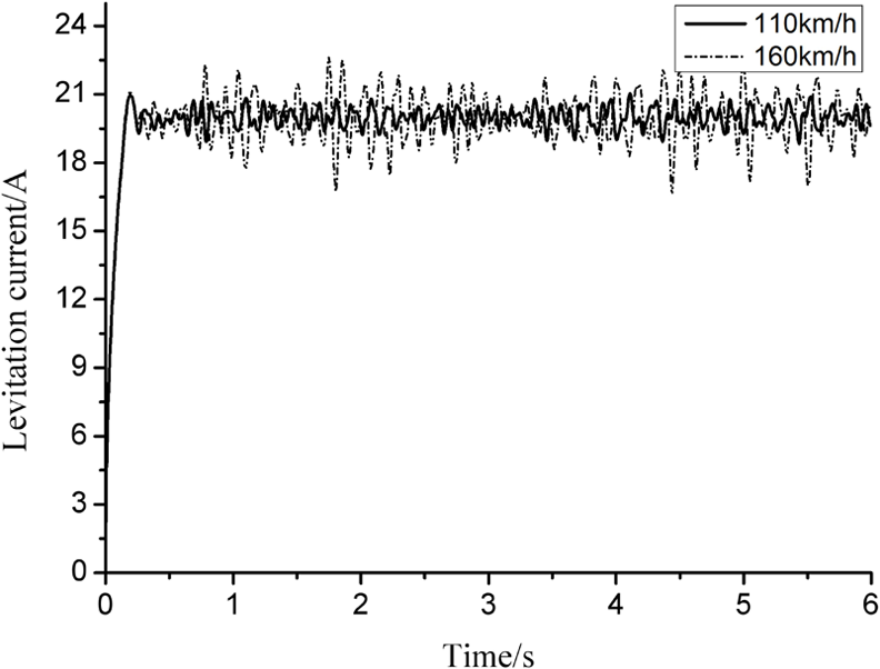
Levitation current dynamics response.
Through the analysis in Figures 12 and 13, we can clearly see that the new-type maglev vehicle has a better dynamic response characteristic for levitation force and levitation current. As shown in Figures 9 and 13, the levitation force can go along well with the change of the gap. It can be known that the levitation controller has a better dynamic adjustment characteristic.
As is well known to us, due to no snake movement, derailment, and other issues caused by wheel–rail contact, the lateral displacements of air springs are investigated by dynamic calculation for maglev vehicle on the straight line. On account of the symmetrical characteristics of modules 1 and 3, only the lateral displacements of air springs of modules 1 and 2 are studied on the straight line condition with two kinds of vehicle speeds being considered, which are 110 and 160 km/h. The lateral displacements of the air springs of modules 1 and 2 are shown in Figures 14 and 15, respectively.

Lateral displacement of air spring at the speed of 110 km/h.
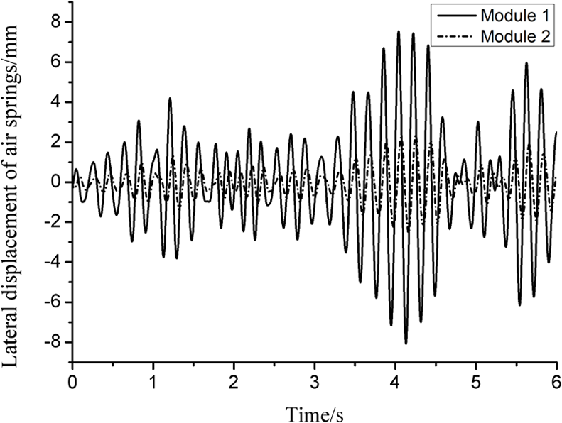
Lateral displacement of air spring at the speed of 160 km/h.
From Figures 14 and 15, it proves that the lateral maximum displacement of module 1 is 2.7 mm at the speed of 110 km/h or 7.8 mm at the speed of 160 km/h. And the lateral maximum displacement of module 2 is 0.8 mm at the speed of 110 km/h or 2 mm at the speed of 160 km/h. All of these are less than 15 mm.
To sum up, through the analysis from Figures 9–15, the following results have been given. The new-type maglev train can run stably at the speed of 110 and 160 km/h on the straight line with better levitation stability and ride comfort. It can be seen clearly from Figures 9–15 that the fluctuation range of the levitation force, levitation current, levitation gap, acceleration of car body, and lateral displacement of air springs are larger along with running faster.
The dynamics simulation on the curve segment
Sometimes, the maglev vehicle will run over the curve track, so the dynamic characteristics of the vehicle on the curve track are also extremely important. Therefore, it is urgently necessary to study the dynamics performance of the new type of maglev vehicle on the curve track.
Assuming that the total length of the track is 300 m, the length of straight line and the length of transition curve line are 40 and 60 m, respectively. The minimum radius of the curve line is 75 m, and the running speed of the vehicle is 30 km/h.
Since the dynamic characteristics of the new-type maglev train have been discussed on the straight line in 3.1, for better studying the dynamics characteristics of the new-type maglev vehicle on the curve track, the effects of the track irregularities would be ignored in the dynamics simulation of the vehicle on the curve track. What should be focused on instead are the dynamic characteristics of the levitation gap, the lateral rolling angle, the lateral vibration acceleration of car body, the lateral acting force of air springs, and the relative lateral displacement of the module 2 while the vehicle runs over the curve track. Taking the left side of the module 1 as the research objection, levitation gap dynamic response characteristics are shown in Figure 16.

Levitation gap.
From the simulation results of Figure 16, it can be seen that the maximum displacement offset of the levitation gap relative to the static equilibrium position is about 0.2 mm during the whole operation process of the vehicle. It can be concluded that the maglev system has a better levitation stability on the curve track. When the vehicle runs over the curve track, because of the effect of centrifugal force, a slightly upward movement of the left-side levitation frames would be generated. Therefore, it is inevitable that a lateral roll phenomenon of the levitation frames will come into being. The maximum displacement offset of the levitation gap is only 0.2 mm, which can indirectly prove that the single anti-roll beam has a better anti-roll characteristic. The anti-roll characteristics of the new-type suspension frame and car body are shown in Figures 17 and 18, respectively. Due to the symmetry of the vehicle, only the suspension modules 1 and 2 are explored in Figure 17.
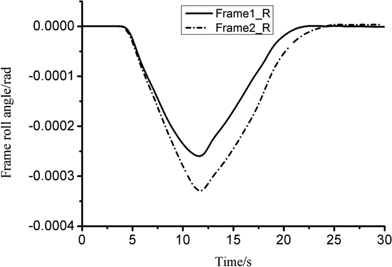
Frame lateral roll angle.
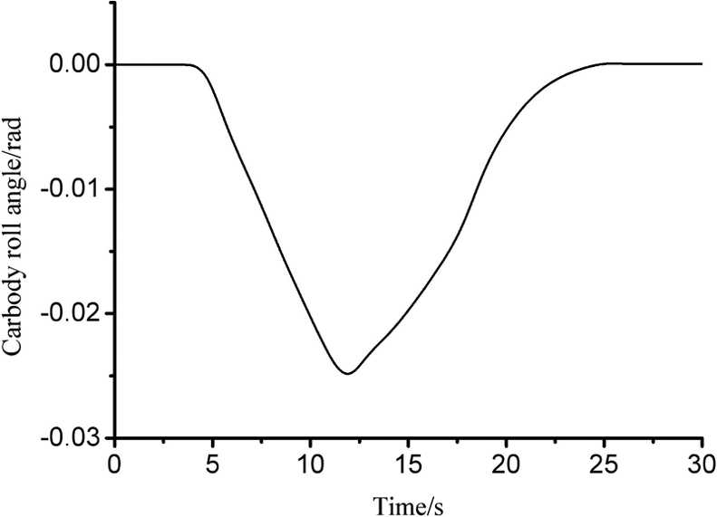
Car body lateral roll angle.
From the simulation results of Figures 17 and 18, it is clear that the maximum roll angles of the suspension frame and car body are less than 0.0004 rad and less than 0.03 rad, respectively. It can be concluded that both of the car body and suspension frame have a better anti-roll characteristics.
Due to the abolition of the steering force, when the vehicle is running over a small radius curve track, the guiding force is undertaken by the lateral force of the secondary suspension air spring. Thus, the investigation of dynamic characteristic of the secondary suspension air spring is absolutely necessary. In virtue of the symmetry of the suspension frame, just the lateral air spring force of module 1 on the right is explored, which is shown in Figure 19.

Air spring lateral force.
From the simulation results of Figure 19, it is shown that the maximum lateral force of the air spring is about 5.7 kN. Taking into account the lateral stiffness of the spring, it can be concluded that the lateral maximum displacement of the air spring relative to car body is only about 38 mm, and the value is within acceptable limits. To sum up, the new type of maglev train can pass through the curve of radius of 75 m at the speed of 30 km/h with full load.
Experimental test
As the maximum operating speed of the new-type maglev vehicle is 140 km/h, for verifying the rationality of the new-type walking mechanism of the maglev vehicle, a 1:1 model of the single maglev frame is devised to test the validation. Experimental subjects are shown in Figure 20. The external excitation of specific track irregularity is applied to simulate the operating conditions at 140 km/h on the straight line. Additionally, the relevant experiments are carried out to test the vertical acceleration related to ride comfort.

Test rig. Test point 1: vertical vibration acceleration of car body center and Test point 2: vertical vibration acceleration of levitation frame.
The test results of the vertical accelerations of car body and the levitation frame are shown in Figures 21 and 22, respectively, when the levitation system keeps levitation stability after 2 s.
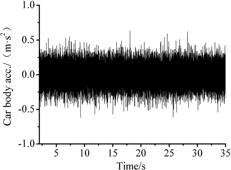
The vertical acceleration of car body.

The vertical acceleration of levitation frame.
According to the analysis on Figures 20 and 21, when the single new-type levitation frame runs at 140 km/h, there is no abrupt change on the accelerations of car body and levitation frame. It suggests that the system can realize perfectly well stability levitation. Meanwhile, the maximum of vibration acceleration of car body associated with riding comfort closely is only 0.5 m/s2 that meets the demand less than 1 m/s2 on vertical acceleration.
Conclusion
Currently, the HSST-type walking mechanism usually is applied into the walking mechanisms of low-speed maglev train at home and abroad. To further enhance the comprehensive competitiveness of low-speed maglev train in the field of urban rail transit, a new type of walking mechanism is developed. The new walking mechanism can greatly improve the traction characteristics of linear motors, and through dynamic simulation analyses, major conclusions are as follows:
The new-type maglev train can steadily run over the straight line at the normal speed of 110 km/h and also at the higher speed of 160 km/h, with a better riding comfort. The maximum running speed of the new-type maglev vehicle is increased by 50 km/h, compared with the traditional HSST series maglev train.
The new-type walking mechanism is simpler and lighter, compared with the walking mechanism of traditional HSST series maglev train. The maglev vehicle with the new-type walking mechanism is not only helpful to decrease the cost of production and maintenance, but also increase the carrying to a certain extent.
The new type of maglev train can steadily pass through the curve of radius 75 m at the speed of 30 km/h with a better ride comfort.
Footnotes
Handling Editor: Elsa de Sa Caetano
Declaration of conflicting interests
The author(s) declared no potential conflicts of interest with respect to the research, authorship, and/or publication of this article.
Funding
The author(s) disclosed receipt of the following financial support for the research, authorship, and/or publication of this article: The authors thank National Key R&D plan Funded projects (grant nos 2016YFB1200601-A03, 2016YFB1200602-13) for their aid and support.