
Abstract
In this article, based on crack surface boundary conditions, the complex stress functions for a tunnel containing a radial crack under compression was obtained, and boundary collocation method was applied to the determination of the unknown coefficients of the complex stress functions. The stress intensity factors were obtained through the complex stress functions, and the results have been validated by numerical simulation using ABAQUS code and by the experiments of tunnel models under compression. The results show that the numerical results using ABAQUS code and the experiment results agree well with the theoretical results by the complex functions, which indicates that the analytical method for determining the stress function and the stress intensity factors proposed in this article are effective and reliable.
Keywords
Introduction
With increasing scale of tunnel constructions in mining and transport engineering, a series of tunnel accidents have been exposed, such as rock burst and roof fall. Natural joints or cracks are frequently encountered in rock mass, and they are distributed randomly around tunnels. Meanwhile, in the process of rock excavation, under the action of explosive detonation, blast-induced radial cracks will occur in the surrounding rock,1–3 which could largely weaken tunnel stability. It is expected that as crack orientation differs, the effect extent on tunnel stability will vary, but these are not clear yet. In order to clearly understand the effect of cracks on tunnel stability, it is essential to implement the corresponding theoretical, experimental, and numerical studies so as to obtain a better understanding of the dominant parameters that control tunnel stability.
Using complex stress functions, the basic equations for solving the plane problems of elasticity were proposed by Muskelishvili 4 in his famous book. For the problems of a crack emanating from a hole, researchers usually used analytical method and numerical method to study. For example, Bowie 5 used a conformal mapping technique to study the problem of a radial crack situated at the edge of a circular hole. Berezhnitskii 6 studied the problem of a crack emanating from an elliptical hole using the integral equation method. Tweed and Rooke 7 studied this problem using Mellin transform technique, but this method is unsuitable to treat complex configurations. Rubinstein and Sadegh 8 considered a circular hole with an arbitrary positioned edge crack using dislocation density distribution function. Woo 9 studied the mixed mode problem of cracks emanating from a circular hole in a finite plate. Wang et al. 10 proposed a group of stress functions for the problems of a crack emanating from a hole with different shapes (including circular, elliptical, rectangular, or rhombic hole). Wang 11 studied the stress intensity factors (SIFs) for an infinite plate with many collinear radial cracks emanating from many circular holes under biaxial loading. Wang and Chau 12 derived a new boundary integral equation for plane elastic bodies containing cracks and holes and subjected to mixed displacement/traction boundary conditions, and proposed a new boundary element method based on this formulation. Yan 13 studied SIFs for cracks emanating from a triangular or square hole in an infinite plate subjected to internal pressure by means of a boundary element method. Zhao et al. 14 proposed an analytical method for calculating the SIF of an infinite plate containing multiple hole-edge cracks by complex variable functions. Through photoelastic experiments, Wang et al. 15 analyzed the SIFs of cracks around a tunnel. Through tunnel model tests and numerical analysis, Zhu et al. 16 and Li et al.17,18 studied the effects of principal stress orientation and crack orientation on tunnel stability, and Fan et al. 19 investigated the effect of the ratio of tunnel depth to its width on tunnel stability. Using multi-domain boundary element method, Wang et al. 20 studied the influence of cracks on the stability of the surrounding rock of a laneway. Although the problems of a crack emanating from a hole have been studied by many researchers, less attention has been paid to the issue of a crack emanating from a horseshoe-shaped tunnel edge and the effect of crack orientation on tunnel stability.
In this article, a horseshoe-shaped tunnel in an infinite rock mass with a radial crack emanating from the tunnel edge is considered which is a through-thickness crack, and for simplicity, a plane strain tunnel model is established to yield the analytical solution of SIF. The tunnel model is under biaxial compression, which is different from those references mentioned above in which the loads were tensile. Under compression, cracks in rock mass are closed in general, and crack surface friction will affect crack tip SIFs significantly; thus, it should be considered in the study of cracks under compression.21–24 The tunnel is inside an infinite plane, and the corresponding complex stress function can be obtained based on the stress conditions of crack surfaces. However, the stress functions consist of a group of unknown coefficients, and they have to be determined in order to obtain the complex stress functions. In this study, boundary collocation method (BCM) has been applied in the determination of the unknown coefficients, which is a simple and accurate numerical method, and has been well established by many researchers.25–28 After the unknown coefficients have been obtained, the crack tip SIFs can be obtained according to the definition of mode I and mode II SIF.
Although the crack tip SIFs can also be obtained through finite element (FE; ABAQUS code) numerical simulation, the corresponding analytical solution is still necessary and significant because the FE simulation is approximate, and the results may have a large error and uncertainty.
Stress functions
and
for a tunnel with a radial crack
For the problem of a tunnel containing a radial crack as shown in Figure 1, we define a basic Plemelj function as

where
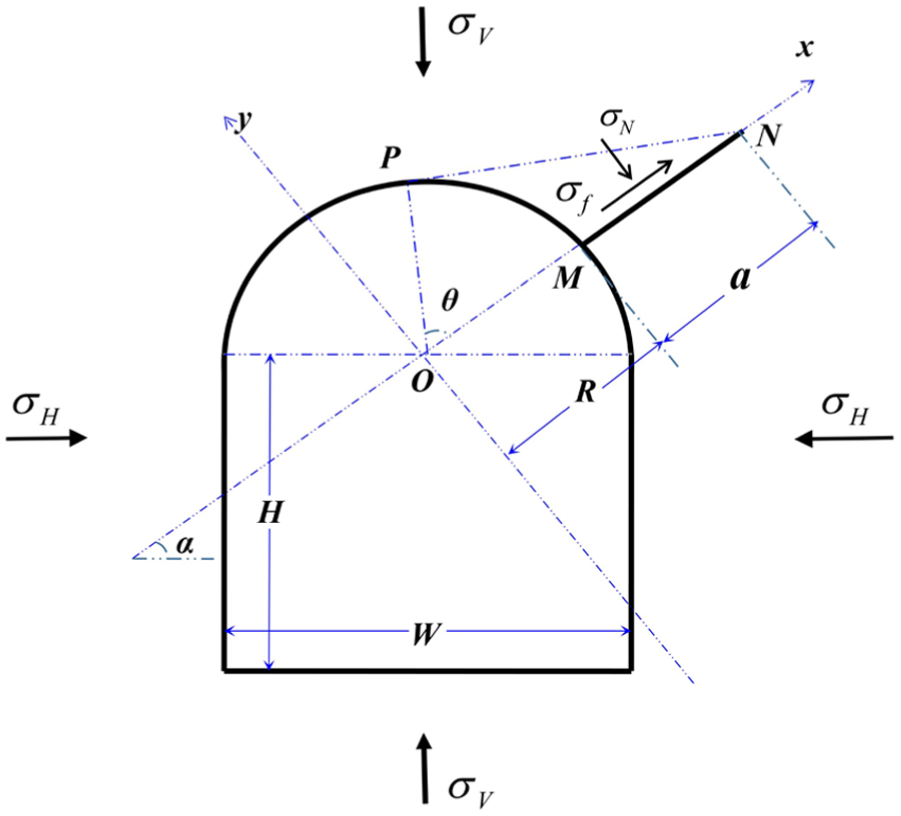
Sketch of a tunnel with a radial crack under compression.
It can be seen that


Sketch of a simple closed path.
According to Zhu,
22
for a tunnel containing a radial crack under the far-field compressive stress

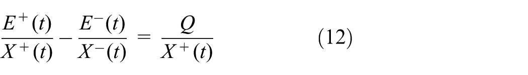
where Q is a constant, Φ(t) and Ω(t) are two stress complex functions, and

It should be noted that if the shear stress
According to the stress single-valued condition in multi-connected zones in an infinite plane, the stress complex functions Φ(z) and Ω(z) can be written as

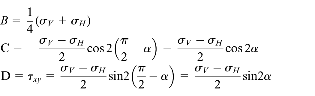
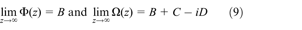
where ν is Poisson’s ratio; B, C, and D are constants, and they can be determined by the far-field compressive stresses, that is
From equations (7) and (8), one can have
Let


Equations (10) and (11) are simple Hilbert problem, and dividing by
Let

According to the theory of Cauchy integral on an arc, the general solution of equation (13) can be written as

where
From equation (14), one can have

Equation (11) can be rewritten as

This means that the function F(z) is analytic in the entire plane except possibly at infinite where it can at most have a pole. Hence, by Laurent’s theorem, F(z) is a polynomial, and considering the condition that

From equations (15) and (17), the two complex stress functions for the case of tunnel with radial crack under compression can be formulated as


where

where

In order to get the solution of
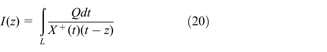
For the radial crack, the integrals along Lk (k = 1) in equation (20) can be expressed in terms of integral along a lacet Ck (k = 1) surrounding it as shown in Figure 3, and the integral over the lacet can be evaluated by the residue theory. Considering the contour integral around the lacet Ck (k = 1), one can have


An arc and a lacet surrounding it.
It can be seen that the second and the fourth integrals in equation (21) tend toward zero as ρ→0, and combining equation (2), one can have

From equation (22), the relationship between the integrals along a crack Lk and along its lacet Ck can be obtained

Using equation (23), equations (18) and (19a) can be rewritten as


From the residue theory, the integral in equation (24) along the contour C can be expressed in terms of the sum of the residues at point z and at infinity; thus, equation (24) can be rewritten as
where
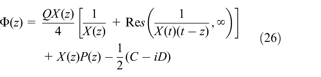
By simplifying, equation (26) can be expressed as

Equation (27) can be written in a simple form

Similarly, the function

where
Stress boundary condition
Generally, stress functions can be written as

where

where


where
According to Figure 4, the stress boundary condition can be expressed as


where

Sketch of the relation of stresses versus the forces on a boundary.
The parameters of l and m on different tunnel edges according to Figure 1.

Determining the coefficients
by BCM
In order to determine the unknown coefficients
Substituting the stress functions
For each collocated point on the tunnel edge, one can obtain the coordinate z and the direction cosine l and m, as well as the boundary stress conditions
In this study, the number of summation terms k involved in equations (28) and (29) is truncated to 17, that is, k = –15, –14, …, –1, 0, 1. Based on the above procedure and parameters, the 17 coefficients
It should be noted that one can use resultant stress boundary conditions to determine the unknown coefficients Ck, which has been applied in the BCM by many researchers.10,21,25,28 However, using general stress boundary condition is simple and easy, whereas using resultant boundary condition sometimes is easily confused with the real and imaginary parts.
SIFs for a tunnel containing a radial crack
The SIFs

Substituting equation (28) into equation (37), the SIFs can be rewritten as
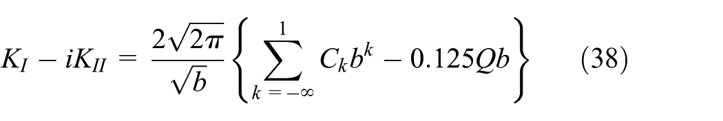
The dimensionless SIFs can be expressed as
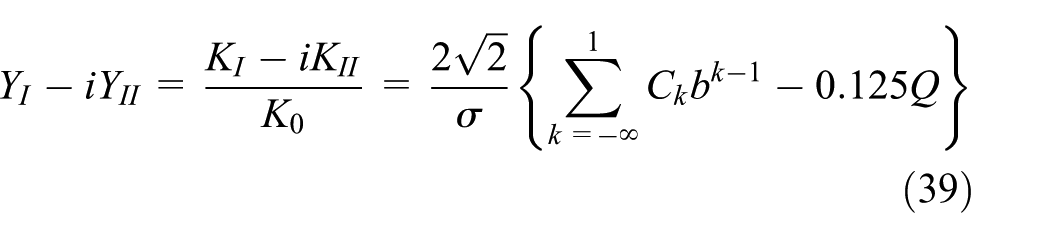
where

Substituting equation (40) into equation (39), one can have


Equations (41) and (42) are the formulas of the dimensionless SIFs for tunnel containing a radial crack under compression, and the SIFs
The calculation results show that the mode I SIF KI is negative, which means that the cracks under compression will close, and the corresponding crack tips do not have stress concentration. Actually, the compressive load will cause compressive stress at crack tips, which will have a negative effect on crack propagation, but the effect extent of the negative KI is not clear yet. 22 Therefore, in this study, the negative KI is not considered, and only mode II KII is calculated.
Figure 5 shows the analytical results obtained by equation (42) for an infinite plane containing a tunnel with a radial crack under biaxial compression with different ratios of

Analytical results of dimensionless SIF YII versus crack inclination angle α from equation (42) for an infinite plane containing a tunnel with a radial crack under biaxial compression.
Validation of the theoretical results
In this chapter, a numerical simulation using FE code ABAQUS is implemented, and the results are compared with the theoretical results. In addition, experimental study is also implemented to validate the theoretical solutions.
Validation through FE simulation by ABAQUS code
In order to accurately simulate a tunnel with a crack, the dimensions of the numerical model should be large enough because the theoretical results were obtained based on an infinite plane containing a tunnel. In this study, a numerical model of a square plate measuring 120 m in length and 120 m in width is established, as shown in Figure 6. The tunnel’s height H and width W are 5 and 3.5 m, respectively, and the length a of the radial crack equals to W/2, that is, a = 1.75 m. In this FE simulation, the vertical stress

A finite element model used in ABAQUS code.
Figure 7 shows the analytical solution obtained from equation (42) and from the FE simulation results using ABAQUS code. The dimensionless YII by ABAQUS code basically agrees with those analytical results from equation (42), but there are still some slight errors between them in Figure 7. The reason is that the theoretical results of SIFs is based on an infinite rock plane, whereas the FE simulation results by ABAQUS code is based on a finite square plate with a centralized “tunnel.”

Comparison of the dimensionless YII between the analytic results from equation (42) and the simulation results from ABAQUS code: (a) σH/σV = 0.00, (b) σH/σV = 0.20, (c) σH/σV = 0.40, and (d) σH/σV = 0.60.
Tests of tunnel models with a radial crack
In order to validate the theoretical results, experimental study using tunnel models is implemented. The tunnel model is a plate specimen with a centralized horseshoe-shaped “tunnel” with a single radial crack, as shown in Figure 8, and the plate is 350 mm in length and 350 mm in width, and 100 mm in thickness, and the “tunnel” is 60 mm in height and 50 mm in width. The tunnel’s arch consists of a semi-circle, and the radius of the circular arch is 25 mm. The crack inclination angle

A tunnel mode and the loading device.
The tunnel models were loaded vertically by electrohydraulic servo control device (500T), and the lateral deformation was confined by the hydraulic jack and the steel plates as shown in Figure 8. Based on the lateral deformation is zero, the relationship between the horizontal stress σ3 and the vertical stress σ1, according to the elastic theory, is σ3 = vσ1, where ν is Poisson’s ratio.
In order to decrease the influence of uneven surface, the specimen surfaces were polished using grinder before loading. The specimen surfaces were also smeared with a kind of lubricant, which can avoid the effect of the friction between the specimen and the loading device. These measures can ensure a better loading condition and improve the accuracy of testing results.
The fracture patterns of the tunnel models containing a crack emanating from the tunnel roof with different inclination angles α under biaxial compressions are shown in Figure 9. It can be seen that crack inclination angles affect tunnel model failure largely.

Fracture patterns of tunnel models with a radial crack under compression: (a) α = 0°, (b) α = 30°, (c) α = 45°, (d) α = 60°, (e) α = 75°, and (f) α = 90°.
In order to compare the critical compressive stresses predicted by the analytical solution equation (42) with those testing results, based on the relation of mode II SIF KII versus the major compressive stress σ1, that is,

where the fracture toughness KIIC of the cement mortar material measured is
Using equations (43) and (42), the critical compressive stresses for the tunnel models with an inclination crack can be predicted, and the results are compared with the testing results in Figure 10. It can be seen that basically, the critical compressive stresses predicted by equations (42) and (43) agree with the tunnel model testing results, and as the crack inclination angle is 45°, the corresponding critical compressive stress is the lowest under the conditions that

Comparison of the tunnel model testing results with the prediction results by equations (42) and (43).
Conclusion
For a tunnel with a radial crack emanating from the tunnel edge, the complex stress functions were obtained according to the crack surface stress condition. BCM was applied in the determination of the coefficients of the stress functions, and the SIFs can be determined using the stress functions. In order to validate the theoretical result, numerical simulation using ABAQUS code and tunnel model compressive tests were implemented, and from this study, the following conclusion can be obtained:
For a tunnel with a radial crack emanating from the tunnel roof, the stress functions can be obtained based on crack surface boundary conditions, and the coefficients of the stress functions can be effectively determined by BCM.
The theoretical result agrees well with the numerical simulation results and the tunnel model test results, which indicates that the method determining the stress functions and the SIFs for a tunnel with a radial crack proposed in this article is effective and reliable.
Figure 5 shows that crack inclination angles and the ratios of horizontal to vertical stress affect the SIFs significantly.
For a tunnel with a 45° inclination crack emanating from the tunnel roof, the tunnel model compressive strength is low, and the corresponding tunnel stability is low.
Footnotes
Handling Editor: Ismet Baran
Declaration of conflicting interests
The author(s) declared no potential conflicts of interest with respect to the research, authorship, and/or publication of this article.
Funding
The author(s) disclosed receipt of the following financial support for the research, authorship, and/or publication of this article: This work was financially supported by the National Natural Science Foundation of China (grant nos 11672194 and 11702181), and by Sichuan Administration of Work Safety (grant no. aj20170515161307).