
Abstract
The semi-rigid performance of minor-axis connections is important in the study of overall framework. Experiments were conducted on minor-axis flush end-plate connections under a monotonic load. Numerical simulations were carried out using the finite-element package ABAQUS and compared with the experimental results. The initial rotational stiffness of the connection was calculated using the equivalent T-stub in tension and EC3 component method, and the calculated veracity is discussed. The results show that under the action of a negative bending moment, the failure modes of the minor-axis flush end-plate connection are the out-of-plane bending deformation of the end-plate, local buckling of the bottom flange of the beam, and bending deformation of the bolts. The minor-axis flush end-plate connection is a typical semi-rigid connection. However, the deformations of the flush end-plate could not be accurately calculated using the equivalent T-stub in the tension of EC3 methods. The initial rotational stiffness calculated using the method was much larger than that obtained using the experiment and finite-element analysis. The equivalent simulation is not appropriate if the out-of-plane bending stiffness of the flush end-plate is not obtained accurately.
Keywords
Introduction
Several studies performed on end-plate beam–column connections dealt with major-axis-extended end-plate connections 1 including the effects of column web stiffener, stiffening plate of the extended end-plate and thickness of the end-plate, bolt pretension force and buckling force, and number of tensile bolts. Furthermore, many extensive studies focused on the moment–rotation curve models of major-axis-extended end-plate connections. The analysis of deformation characteristics and failure modes has provided convenience for design practices. Nevertheless, the minor-axis is an important part of a steel frame connection. Its performance has a significant effect on the entire structural system. It is necessary to consider the properties of the minor-axis in the higher analysis of a space structure. Therefore, the study of the minor-axis of a space frame is indispensable.
The recent studies on major axis semi-rigid connections 1 mainly described the characteristics of the mechanical model of bending–moment–rotation curves.2,3 In the studies on end-plate connections, scholars mainly focused on the static performance, 4 seismic performance, 5 bolt performance, 6 theoretical system analysis, 7 and finite-element analysis. 8 Also the bending–moment–rotation characteristics of major axis in end-plate connections9,10 as well as the mechanical properties of minor-axis connections 4 had been paid attention too. Thus, the minor-axis flush end-plate connections have been rarely studied.
In this study, experiments were conducted on minor-axis flush end-plate connections under a monotonic load. Numerical simulations were carried out using the finite-element software ABAQUS and compared with the experimental results. The initial rotational stiffness of the connection was calculated using the equivalent T-stub in tension and EC3 component method, and the calculated veracity is discussed.
Description of test programme
Test design and test device
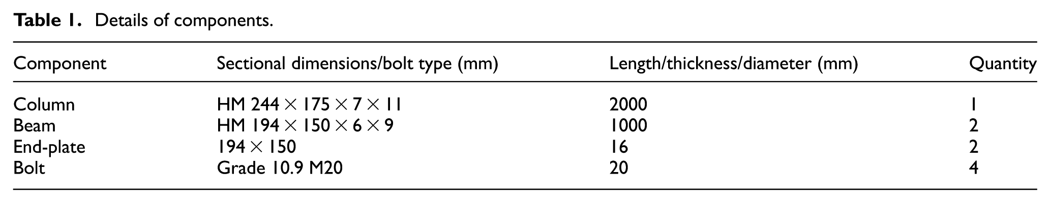
Two specimens of minor-axis flush end-plate beam-column connection with the same dimensions were fabricated. The details of the components are shown in Table 1, and the end-plate is shown in Figure 1. The material properties of specimens depend on the end-plate, beam, and column area. The material performance test results are shown in Table 2. The monotonic loading test of symmetric negative bending moment was carried out on the connection specimens.
Details of components.

Details of the test specimen.
Material properties of test specimens.

As the monotonic loading test progressed (see Figure 2), the axial load was applied and increased to 80% of the yield load obtained from the finite-element simulation on both sides under load control. Then, the load was applied under displacement control, and it was not stopped until the specimen failure.

Test rig.
Testing content and method
As shown in Figure 2, the displacement sensors were set at the both ends of the beam for measuring displacement. The strain gauges were attached to the main part of the connection zone for the stress-state monitoring of the main mechanical parts. The main contents of the test include vertical load of the beam loading end beam, vertical displacement of the loading end, strain of the connection zone, rotation of the connection zone, and connection failure mode.
Finite-element analysis
The finite-element model analysis corresponding to the experiment was carried out based on the finite-element environment ABAQUS/Standard. The steel was modeled as an elastic–plastic intensive material. The parts of the specimen, plates, and bolts were meshed by linear eight-node reduced-integration brick finite elements (C3D8R). TIE constraints (rigid connections between the master surfaces and the slave surfaces) were provided to simulate the welding connections. The contact interactions between the specimen and end-plate were prescribed under the pretension force of bolts by defining the normal and tangential direction behaviors. The load was applied under a vertical displacement control. Positioning constraints were used when assembling to adjust the change in parameters. The finite-element mode is shown in Figure 3.

Finite-element mode and mesh division.
As shown in Figure 4, the test moment–rotation curve is relatively stable in the elastic stage, when some steel components reached their yield limit, leading the loading process into plastic phase, the loading curves would create fluctuations. On one hand, it is because that the plastic deformation of the steel is random, which results in the different deformation on both loading ends. On the other hand, these two loading ends of the specimen produce certain unbalanced moment, because the coordinated loading is not quite precise.

Experimental moment–rotation curves at both ends.
To eliminate these differences, the data of both the ends were averaged before comparing with the finite element modeling (FEM) results (see Figure 5); these obtained curves are in good agreement.

Comparisons of the moment–rotation curves between experiment and FEM.
Figure 6 shows the stress analysis from the FEM of minor-axis connection under symmetric loading conditions. The main deformation of the connection zone is concentrated at the end-plate and connection bolt. The column web slightly affected the mechanical property of the connection zone.

Stress nephogram from FEM under monotonic loading.
EC3 component method
The initial rotational stiffness of end-plate steel connections has been provided in steel specification Eurocode 3: Design of Steel Structures (EC3) 11 using the component method. For the minor-axis flush end-plate connections under a symmetrical monotonic load, the bending plates and tension bolts are the major components affecting the mechanical performance.
Calculation process of component method
The initial rotational stiffness of the connection was obtained using equation (1) in EC3
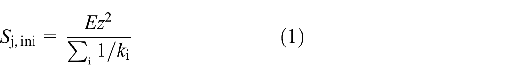
where E is the elastic modulus of the steel, z is the tension arm of the force (see Figure 7(a)), and ki is the stiffness coefficient of the basic component i. The stiffness coefficients of the bending plate and tension bolts are shown in Table 3.
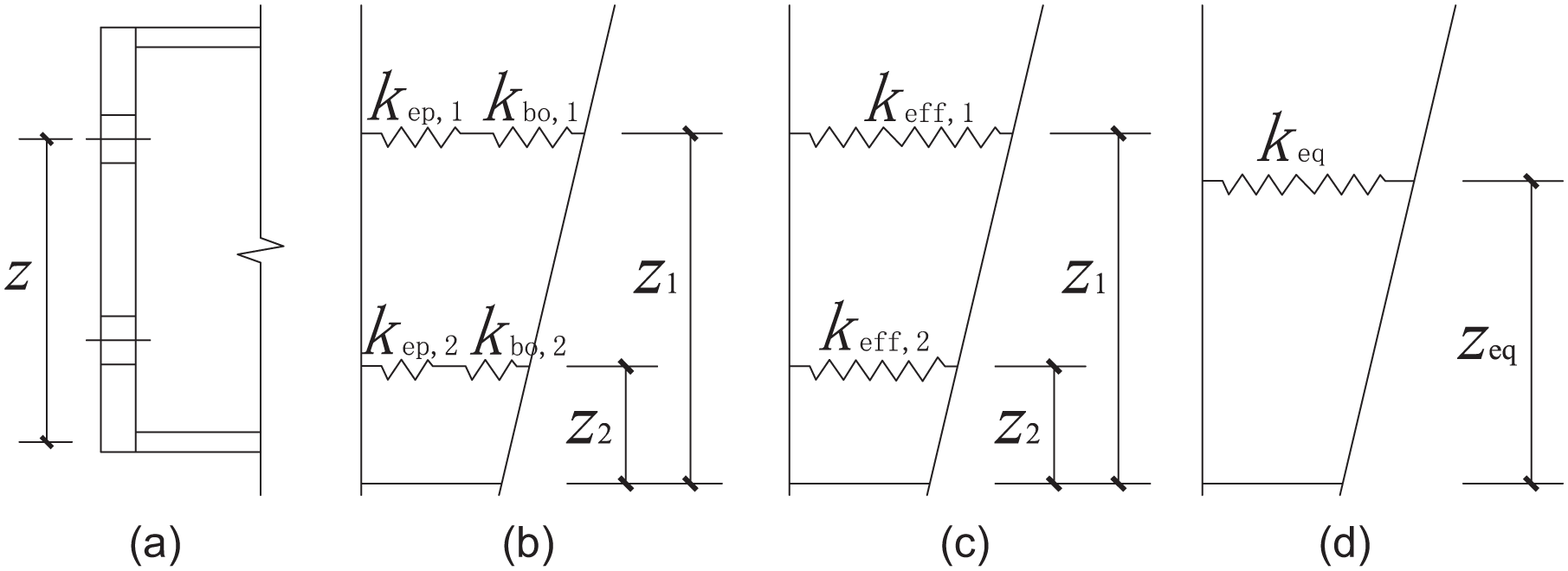
The combination and simplification of the spring components: (a) original section, (b) combination of springs, (c) simplification of springs, and (d) simplification of arms of force.
Stiffness coefficients of components.
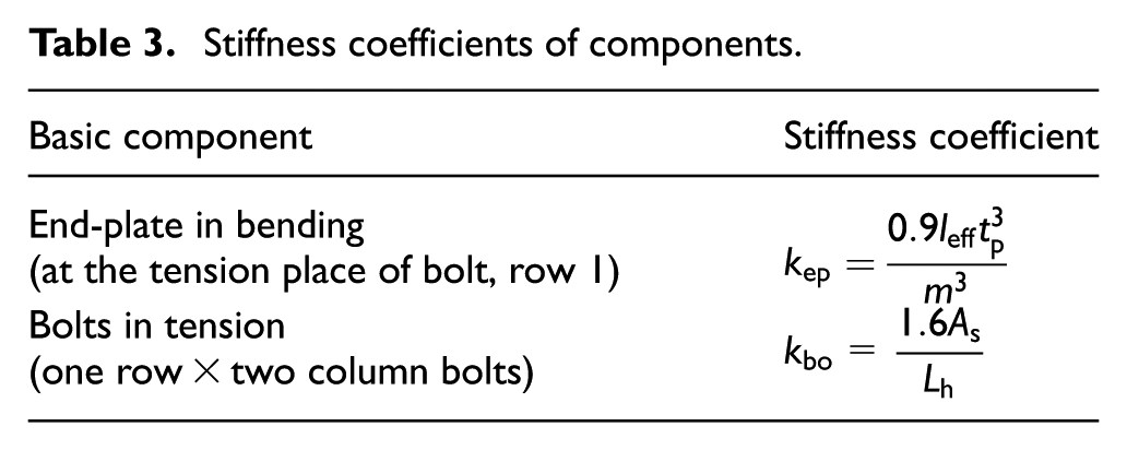
In the stiffness coefficient equations shown in Table 3, tp is the thickness of the end-plate, whereas Lb is the half-length of the combination of the length of bolt bar and the thickness of the washer and nuts.
The mentioned tension arm of force Z and initial rotational stiffness of connection Sj,ini were only used in the situation where one row of bolts is in tension. Hence, EC3 provides the equivalent tension arm of force Zeq, actual stiffness coefficient keff,r, and equivalent stiffness coefficient Keq to calculate the initial rotational stiffness Sj,ini corresponding to more than one row of bolts in tension. The equivalent parameters were defined using the following equations
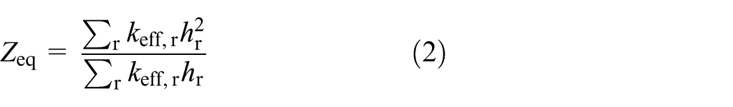


where hr is the distance between bolt row r and the center of compression, the center line of the lower flange of beam. The parameter ki,r is the stiffness coefficient of the basic component i in bolt row r, and keff,r is the actual stiffness coefficient of bolt row r. It consists of the bending end-plate and tension bolt rows in the flush end-plate connection.
This study included two rows of bolts in tension; therefore, the calculation process of the component method in EC3 was based on Figures 7 and 8.

Calculation process of initial rotational stiffness.
Calculation results of component method
The initial rotational stiffness of connections was calculated using the component method. The dimension of H-shaped steel beams was HM 194 × 150 × 6 × 9, matching with end-plate d16 and bolt M20, and the other dimensions were consistent with the finite-element analysis. The calculation results of the component method are shown in Table 4.
Comparisons of initial stiffness values.

FEM: finite element modeling.
Because the fillet weld and washer were absent in the finite-element model analysis, the corresponding dimensions shown in Table 5 are equal to 0.
Calculation results of component method.

More comparisons of the initial stiffness values using the EC3 method are shown in Table 5. Clearly, Table 4 shows that the initial rotational stiffness of the minor-axis flush end-plate connections calculated by the component method in EC3 had a huge variation from the finite-element analysis results. The reasons of the variation are as follows:
First, the equivalent T-stub in tension plays a part. In EC3, the bending end-plate is simulated to an equivalent T-stub in tension considering the beam web and neglecting the beam top flange. The contrasts of the end-plate deformation under a uniform tension force loading on the beam web are shown in Figures 9 and 10.

Deformation nephogram of end-plate from finite-element analysis without flange (mm).

Deformation nephogram of end-plate from finite-element analysis (mm).
In an actual case, the deformation of the top row of bolts in the end-plate is not only caused by the web tension force, but also more by the flange tension force. The actual deformation behavior is clearly different from the equivalent T-stub form that ignores the beam flange, leading to different top displacements. Moreover, the connection rotation is defined as the top displacement divided by the depth of beam. Therefore, the equivalent T-stub is not applicable to simulate the flush end-plate accurately.
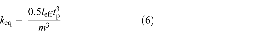
Second, the end-plate is a significant basic component of the connection with its vital bending stiffness. The end-plate has been simulated as an equivalent T-stub to measure the bending stiffness without the actual derivation of bending stiffness in EC3. In the literature, 12 the end-plate was analyzed using the simulation of an equivalent T-stub as well. In this study, the equivalent T-stub was simplified to a simply supported beam under three-point stress, and the initial stiffness was calculated using the component method. The stiffness coefficient of end-plate without considering the bolt bucking force was almost only half of the response stipulated in EC3 (see equation (6))
Moreover, the end-plate should be regarded as a medium with a larger width-to-thickness ratio than a sheet or shell. By reference to the equivalent T-stub simplified in the literature, 12 the end-plate deformation was obtained without considering the shear deformation. Thus, the effect of shear deformation on the end-plate ultimate deformation should be further investigated.
Similarly, the tension stiffness of bolt has made a difference. The initial rotational stiffness of connection was slightly affected by varying the bolt pretension force in a small scale, but it was proved that the existence of pretension force itself made a difference. Nevertheless, the effect of pretension force on the tension stiffness coefficient of bolt defined in EC3 was not considered. Thus, a tension stiffness coefficient considering the pretension force with a significant increase was proposed by GQ Li et al.,
12
see equation (7) where
Moreover, the negative effect caused by buckling force on the tension stiffness coefficient of bolt in EC3 was considered. However, SF Chen 13 showed that the buckling force appeared when the external force was 0.5 times of the bolt pretension force using a connection specimen. Therefore, the buckling force was not considered

where
The initial rotational stiffness of a connection was calculated in the literature
12
using the following steps: (1) first calculate the bending stiffness of end-plate using an equivalent T-stub, (2) calculate the tension stiffness of bolt considering the bolt pretension force, and (3) then calculate the initial rotational stiffness using the component method. The calculation result was 39,886
Conclusion
The minor-axis flush end-plate beam–column connection is a typical semi-rigid connection. Under the symmetrical loading condition, the main deformation of the connection zone is concentrated at the end-plate and connection bolt. The column web slightly affects the mechanical property of the connection zone.
In actual cases, the deformation of end-plate around the highest bolt holes is caused not only by the tension of the beam web, but also mainly by the beam flange.
End-plate significantly affects the minor-axis connection performance, and the bending stiffness has major effects on the entire connection rotational stiffness. The equivalent T-stub method cannot accurately determine the loading features of an end-plate. Further studies are needed on how to obtain an appropriate equivalent mechanical model of a flush end-plate.
Footnotes
Handling Editor: Xiaotun Qiu
Declaration of conflicting interests
The author(s) declared no potential conflicts of interest with respect to the research, authorship, and/or publication of this article.
Funding
The author(s) disclosed receipt of the following financial support for the research, authorship, and/or publication of this article: This study was supported by National Natural Science Foundation of China (grant nos 51778241, 51708226, 51378009, 51378219, 51638009) and by State Key Laboratory of Subtropical Building Science of South China University of Technology (grant nos 2018ZB35, 2017ZB28, and 2017KD22) and by the Fundamental Research Funds for the Central Universities (grant nos 2017BQ086; 2017ZD026).