
Abstract
The flexure-based fast tool servo, which is well adopted to manufacture non-circular section parts, has attracted many researchers’ attention for its cutting-edge characteristics in non-circular turning operation in terms of large output displacement, high bandwidth frequency, and fine surface processing. The geometric design and corresponding parameters configuration of the flexure hinge are deterministic to the performance of fast tool servo. In order to achieve a well-balanced stroke and natural frequency of the fast tool servo, this article proposes a harmony search–based multi-objective optimization method for setting of design parameters. Referring to the Lagrange method, the relationship between parameters of the flexure hinges and stiffness of the mechanism is derived and analyzed. Finite element analysis method is performed which demonstrates a fine agreement between the results from simulations and that from the proposed analytical solutions.
Introduction
To meet a certain special requirement, some of mechanical parts are often designed with non-circular sections, such as ellipse, polygon, and free-form, during the mechanical design. For example, piston is the typical non-circular section part which plays an important role in internal combustion engines operating under harsh conditions with high temperature, high mechanical load, and high pressure. The section form of the piston partially determines the power, fuel consumption, noise, and life span of the internal combustion engine.1,2 To ensure the quality and performance of the combustion engine, the middle convex and varying ellipse pistons are becoming more popular for the characteristics of ellipse section curve. 3 However, for these non-circular and asymmetry parts with complex shapes, the traditional manufacture methods such as contour machining, abrasive machining, and electrical discharge machining cannot meet the accuracy and productivity demands. Ma et al. 4 show that a computer numerical controlled (CNC) lathe equipped with a fast tool servo (FTS) system has a wide frequency range and therefore is a better choice for manufacturing these parts when compared with other machining methods.
When design of the FTS system, it is critical to choose the actuator for the system. Several kinds of actuators can be adopted to drive the FTS systems, such as piezoelectric actuator (PEA), voice coil motor, Lorentz force type actuator, magnetostrictive actuator, and hydraulic actuator. The first three actuators are often adopted to drive the FTS system to manufacture non-circular parts. FTS driven by voice coil motor can travel several millimeters with good dynamic characteristics and linearity, but it has lower frequency response and less accuracy that are driven by PEA. The advantage of Lorentz-type actuator is that it can have longer stroke than those of piezoelectric-based FTS systems. However, the maximum steady-state acceleration is limited by the heat generated in the coil. 5 Magnetostrictive materials are able to generate large displacement under magnetic field, but it has serious hysteresis and heating problems; overall, their performance as reported in literature appears to fall significantly behind that achieved by the PEAs.6–8 Hydraulic servos are relatively less; some long-stroke FTS systems with hydraulic examples can be found in the works by Kim and Tsao. 9 Most FTS systems are driven by PEAs, with the advantages of quick response, high stiffness, nanometer resolution, and frequencies from 20 Hz to 2 kHz. 10 Furthermore, it is easy to control when PEAs are open-loop stable with a particular frequency.11–13 However, piezoelectrically actuated FTS systems also have some disadvantages. The first problem is particularly caused by amplifier mechanisms that are adopted to increase travel; the resonant frequency falls linearly with the increased amplification ratio, which imposes significant limits on the achievable closed-loop bandwidth of such type of FTS. 14 Another problem is that it is difficult to design mechanical structures with large stroke and high natural frequency. As it is well known, if we increase the stiffness of the mechanism along the driven direction, the natural frequency will increase correspondingly; however, it will lead to displacement loss. So how to optimize the geometric parameters of the flexure hinge for the purpose of getting a good performance in frequency and stroke is needed to be considered in the design.
In this article, a flexure-based FTS mechanism for non-circular turning operation is presented. The characteristic of this mechanism is the easy-to-fix sensor which measures the output displacement, and harmony search (HS) optimization method is adopted to optimize the optima results. The remainder of this article is organized as follows. In section “Principle of non-circular turning operation,” the principle of non-circular turning operation is introduced. The design process and prototype of the FTS are described in section “Conceptual design of the FTS mechanism.” The static and dynamic model of the FTS is presented and also the numerical simulation is conducted in section “Mechanics modeling and analysis.” The optimization formulation and HS optimization are introduced in section “Objective function and HS optimization.” Finally, the validation of the optimized results and conclusion is presented in section “FEA validation” and “Conclusion,” respectively.
Principle of non-circular turning operation
Non-circular turning operation is a very complicated process. The relative position and motion between the cutting tool and workpiece in non-circular machining are schematically depicted in Figure 1. When the support table is stopped at a specified position, the cutting tool starts to move along the

where
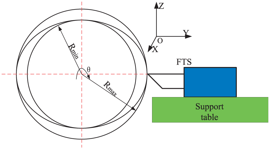
Schematic representation of non-circular section machining.
The reference input signal for the cutting tool motion can be defined based on the aforementioned analysis. So the design requirements of the FTS can be decided by the ellipse parameters with following equation

where
Conceptual design of the FTS mechanism
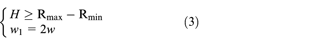
The purpose of this study is to design a flexure-based FTS mechanism driven by PEA for non-circular turning operation. Referring to Figure 1 and equation (2), to fulfill the manufacturing process, the following equation must be satisfied
Based on the practical experience for manufacturing non-circular workpiece, the design requirements of the FTS are listed in Table 1.
Required performance for designed FTS system.

FTS: fast tool servo.
Figure 2 shows three common configurations of PEA-based FTS systems. The most common configuration is shown in Figure 2(a) where the tool, sensor, and PEA are all collinear. There are some advantages of this structure, such as minimizing the internal torques and avoiding decoupling motion and compact size, but properly fixing the sensor may be a challenge work. The configuration is depicted in Figure 2(b) where the tool, sensor, and PEA are parallel but not collinear. One advantage of this configuration is that the sensor may easily be placed collinear with the tool; the other advantage is that with proper place, the PEA designer can amplify or reduce the output displacement of the tool; meanwhile, this configuration will generate coupling displacement. Figure 2(c) shows a configuration where the tool, sensor, and PEA are neither collinear nor parallel. This type of configuration is typically used when space in the direction of the tool motion is limited. The disadvantage of this configuration is that the tool has a rotary motion.

Typical configurations of PEA-based FTS systems: (a) PEA, sensor and tool are collinear, (b) PEA, sensor and tool are parallel but not collinear, and (c) PEA, sensor and tool are neither collinear nor parallel.
The proposed FTS mechanism is depicted in Figure 3; the beam flexure hinge allows a translational motion along the driven direction, which was utilized to reduce the parasitic motion error. The PEA from Physik Instrumente (PI) with large stroke is utilized, and the characteristics about adopted actuator are listed in Table 2. Referring to the properties of the PEA, the stacked PEAs are very sensitive to the lateral force and moment.
16
In order to avoid lateral loads or moments on the PEA, a steel ball is adopted to connect with the moving platform and PEA. In this study, the
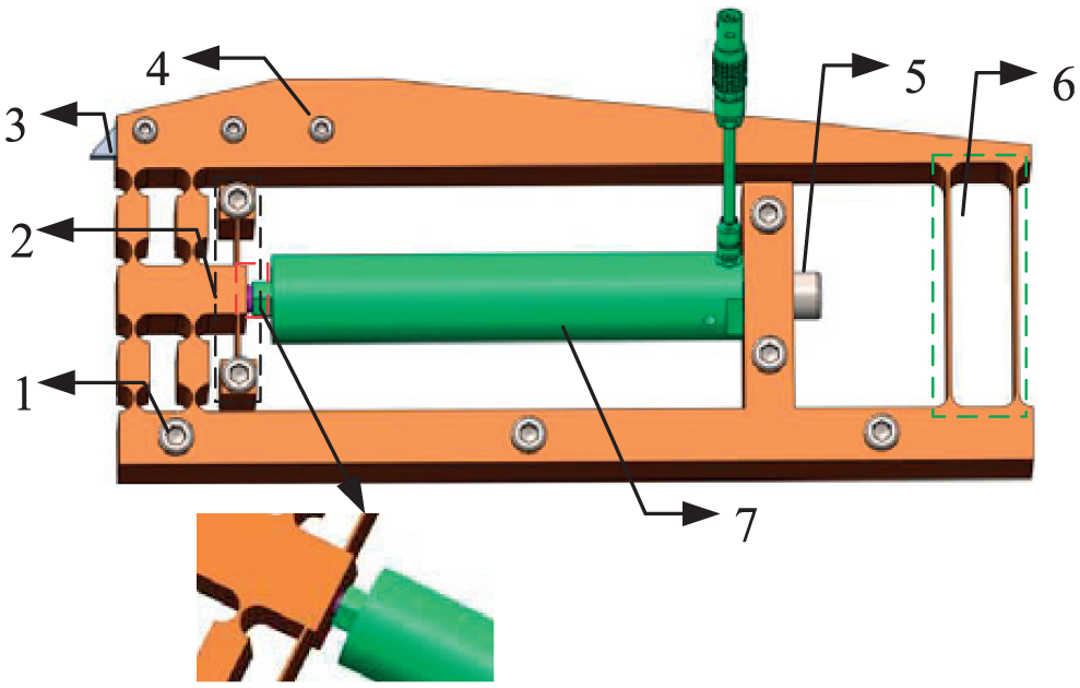
Schematic representation of the designed FTS mechanism: (1) bolt to fix stage, (2) flexure guider mechanism, (3) tool, (4) bolt to fasten tool, (5) preload bolt, (6) beam flexure, and (7) piezoelectric actuator.
Main parameters of the adopted piezoelectric actuator PI 216.80.
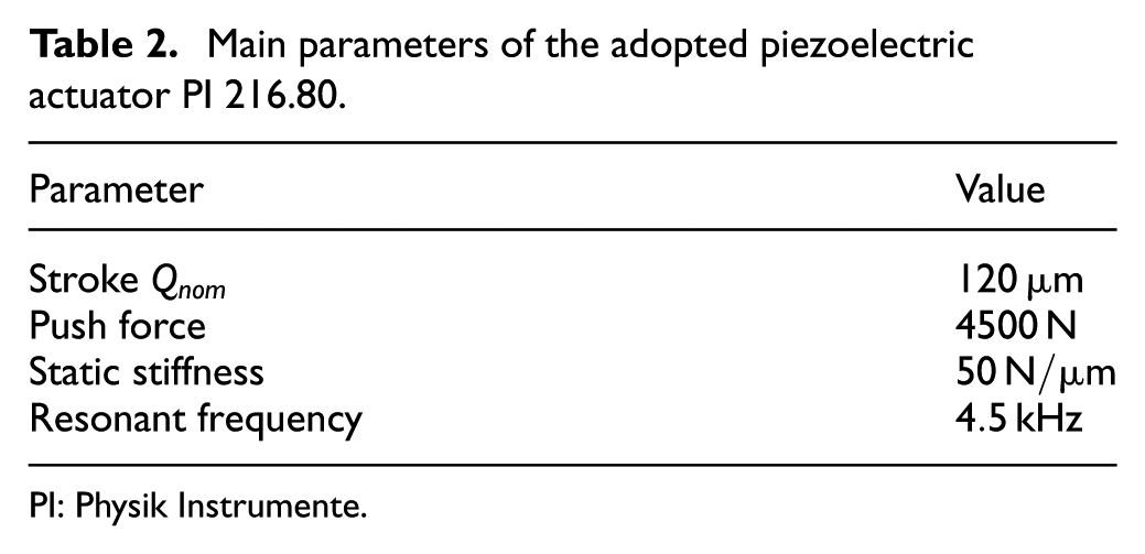
PI: Physik Instrumente.
Mechanics modeling and analysis
The first resonance frequency is very critical for a flexure-based FTS mechanism for precision non-circular manufacturing, which can be used to improve mechanism bandwidth and manufacturing efficiency. In this section, the stiffness and the natural frequency of the mechanism are derived by the Lagrange method.
Dynamic modeling
The schematic diagram of this design is shown in Figure 3; this mechanism adopts two kinds of flexure hinges: one is right circular hinge which has accurate rotation motion and the other is beam flexure hinge which can get large motion scope. In order to get total potential energy of this mechanism, the stiffness of each flexure hinge should be derived first. The developed pseudo-rigid-body (PRB) model is adopted to the flexure-based mechanism for it can simplify the analysis and calculation process with relative high accuracy.
The rotational stiffness of the right circular hinge
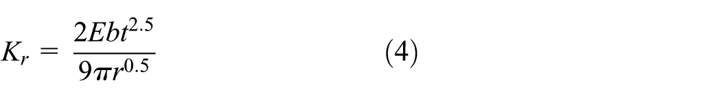
where
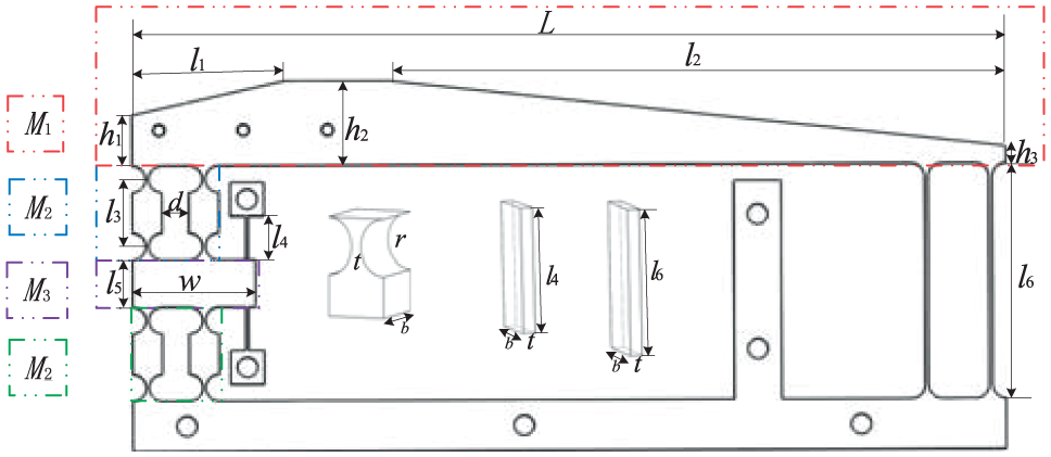
Schematic diagram of the fast tool servo and its parameters.
Consider that both ends of the beam flexure can maintain a constant angle during the actuation, so the PRB model of the beam flexure hinge is depicted in Figure 5. The torsional stiffness of the beam flexure

In this design,

Pseudo-rigid-body model of the beam flexure hinge.
The equivalent dynamic model is presented in Figure 6, where
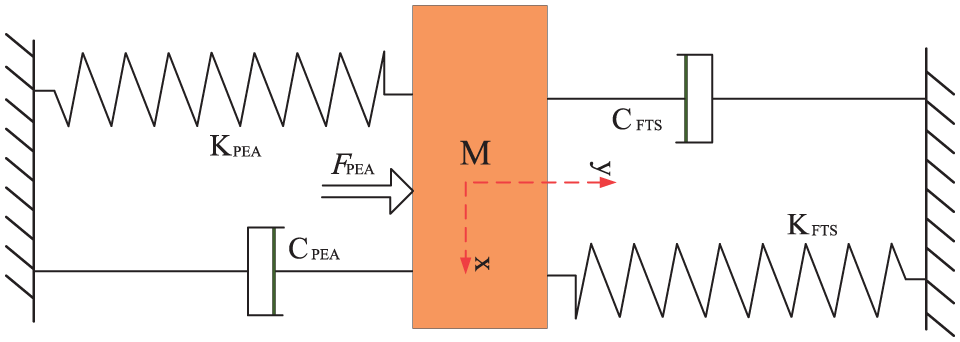
Equivalent dynamic model of the FTS mechanism.
The equivalent mass of the FTS mechanism can be derived as follows

where

The total kinetic energy of the designed FTS mechanism can be expressed as follows

where
The total potential energy of the FTS mechanism can be derived as follows

where
Substituting the kinetic energy and potential energy into Lagrange’s equation of the holonomic conservative system

where
So the dynamic equation of the designed FTS mechanism can be expressed as follows

where

So, the natural frequency

Static modeling
Generally, the PEA is utilized in a restraint condition, and the preload force will reduce the nominal maximum output displacement. Referring to Figure 6, the effective output displacement of the mechanism
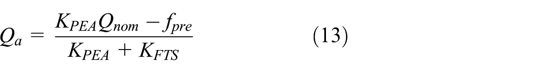
where
The output displacement and frequency of the mechanism are sensitive to variation of dimensional parameters of the flexure hinges. Based on equations (12) and (13), the simulation results of frequency trends and effective output displacement along with the variation of the flexure hinge dimensions are presented in Figures 7 and 8, respectively.
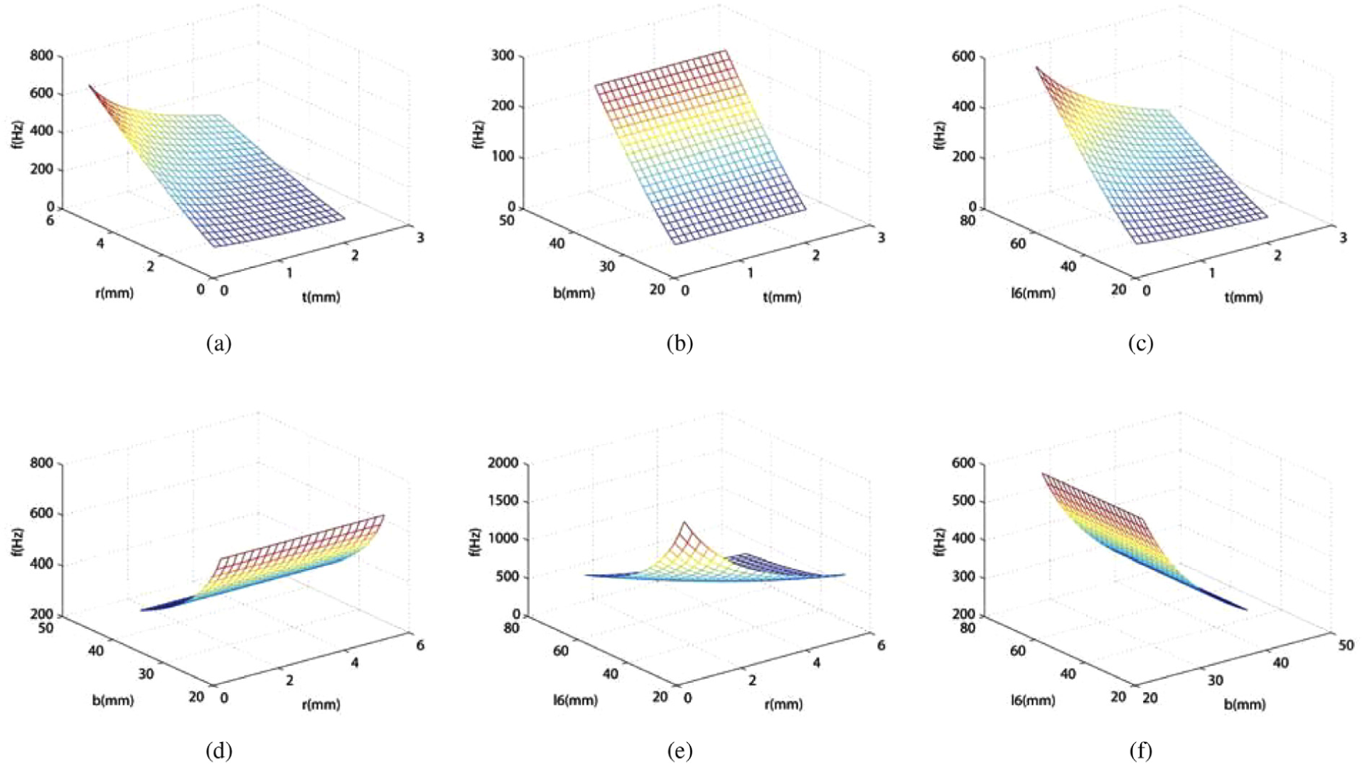
Trends of frequency along with the variation of the mechanism dimensions: (a) frequency with parameters

Trends of effective output displacement with the variation of the mechanism dimensions: (a) output displacement with parameters
Objective function and HS optimization
Objective function
In order to maintain the accuracy of the finished surface, the FTS mechanism needs to have high bandwidth, high acceleration, and high stiffness in the feed direction. So, the high first natural frequency should be maintained for the purpose of getting high bandwidth in order to avoid the resonant vibration and external disturbance. Referring to the simulation results depicted in Figures 7 and 8, some parameters have a positive effect on

Every coin has two sides; the higher stiffness will cause the displacement loss along the driven direction in some degree. So, the displacement of the designed mechanism is the second objective function. As mentioned above, the higher stiffness along the driven direction and larger stroke is contradictory. Therefore, a balanced compromise between the two conflicting objectives is required. The objective function is given as follows

where
Constraint conditions
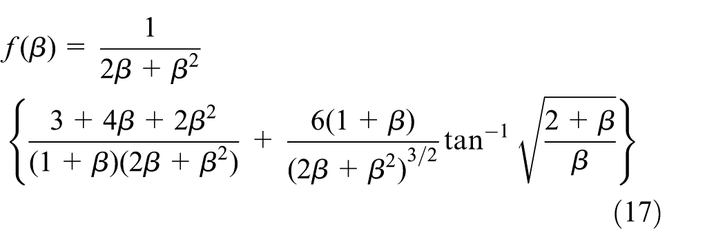
To optimize the architecture parameters, some constraint conditions should be taken into consideration, mainly limited by material properties and manufacturing limit. During the actuation process, the deformation of the flexure hinge must be elastic. So, when the input stroke
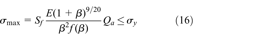
where
Referring to the experience, if the thickness

So, after the values of aforementioned variables have confirmed, the following parameters also can be determined
HS optimization
The HS was initially proposed by Geem 17 and applied to solve the optimization problem of water distribution networks in 2006. As a novel population-based meta-heuristic algorithm, during the recent years, it has gained great research success in the areas of mechanical engineering, control, signal processing, and so on. With mimicking the rules of various combining pitches, HS has two distinguishing operators different from other algorithms: harmony memory considering rate (HMCR) and pitch adjusting rate (PAR) that are used to generate and further mutate a solution, respectively. The flow chart of the HS algorithm is illustrated in Figure 9, which can be summarized in four steps: (1) initialization of the HM; (2) improvisation of new harmony; (3) inclusion of the newly generated harmony in the HM, provided that its fitness improves the worst fitness value in the previous HM; and (4) returning to step 2 until a termination criteria is satisfied.

Flow chart of the HS method.
The above improvisation procedure is mainly controlled by two different probabilistic operators, which are sequentially applied to each note so as to produce a new set of improvised harmonies or candidate solutions.

where
Results of optimum design
The HS algorithm is implemented in MATLAB (2013b), the optimum results are shown in Table 3, and the convergence process in searching optima is depicted in Figure 10. These optimized results can provide a better guidance to design and fabricate the proposed prototype. Taking the machining accuracy of the machine tools into consideration, we give a set of approximation value to the parameters
Design parameters obtained by HS method.


Convergence process.
FEA validation
The FEA method is employed to validate the optimum design using ANSYS software. The solid-type Quad.4 with 182 node was the chosen element to mesh the stage during the whole validation process. As shown in Figure 11 and Table 4, the effective stroke of the tool holder is 96.75 μm under the 100 μm input displacement, and the parasitic displacement is 0.098 μm (coupling ratio: 0.101%); thus, the linearity of the mechanism in long motion range is guaranteed. The static stiffness along the driven direction of the mechanism is

The simulation of FTS mechanical structure under 100 μm input: (a) displacement simulation and (b) static simulation.
Displacement and cross-coupling errors.


Stiffness curves of the mechanism.

Modal analysis of the flexure-based mechanism with optimum parameters: (a) first natural mode: 156.77 Hz, (b) second natural mode: 721.32 Hz, (c) third natural mode: 909.05 Hz, and (d) fourth natural mode: 941.17 Hz.
Conclusion
This article proposes a novel flexure-based FTS mechanism for non-circular turning operation via considering the balance between stiffness and stroke along the driven direction of the mechanism. By extending the typical configurations of the FTS systems, a new mechanical structure is proposed, and the relationship between parameters of the flexure hinges and stiffness of the mechanism is derived and analyzed using Lagrange method. To get a well balance with natural frequency with effective stroke, the HS method is adopted to search the optimized values for flexure hinge parameters. In the experimental verification, the FEA method is utilized to validate the correction between the proposed analysis and the obtained optima, which indicates that designed mechanism can provide a good linearity motion in certain long range. In the future, additional experimental studies will be conducted to further validate the application performance of the proposed model in various domains.
Footnotes
Handling Editor: Gang Xiao
Declaration of conflicting interests
The author(s) declared no potential conflicts of interest with respect to the research, authorship, and/or publication of this article.
Funding
The author(s) disclosed receipt of the following financial support for the research, authorship, and/or publication of this article: This work was supported by Research Committee of University of Macau (MYRG2016-00160-FST) and Macao Science and Technology Development Fund (grant nos 121/2016/A3; 015/2015/AMJ).