
Abstract
This article presents an approach for improving the water film’s carrying capacity in the gear-shaft/journal-bearing interface in water hydraulic internal gear pumps by applying micro shapes to the gear shaft’s surface. The micro shapes are in the shape of sinusoidal waves that can be determined by three design parameters in terms of the wave number, the wave amplitude, and the convex ratio. An elasto-hydrodynamic model, which involves the evaluations of the film height, the film pressure, and the bearing deformation, is proposed to analyze the performance of the micro shapes, and the model is validated by comparison with the results from other research groups. By observing the performance of the micro shapes, it is seen that the convex shape has a positive effect while the concave shape has a negative effect on the film’s carrying capacity, and the carrying capacity decreases as the wave number increases. Additionally, further discussions are performed with respect to the design parameters of the convex shape under different operating conditions, suggesting that the wave amplitude should be maintained 0.8–0.9 times the maximum deformation of the bearing and the convex ratio should be 1/3.
Keywords
Introduction
Water hydraulics is becoming more and more popular in many occasions, especially in pollution-free occasions such as food and drug processing facilities and nuclear industries, due to its advantages over traditional oil hydraulics in terms of environmental friendliness, nontoxicity, and non-flammability.1,2 Water hydraulic internal gear pumps (WHIGPs) represent a promising power unit in water hydraulics due to their advantages of compactness, low noise level, and low flow ripple. 3 The gear-shaft/journal-bearing interface represents one of the key design elements of WHIGPs, and this article is focused on the micro shapes applied to the gear shaft’s surface for the purpose of improving the carrying capacity of the water film in the gear-shaft/journal-bearing interface.
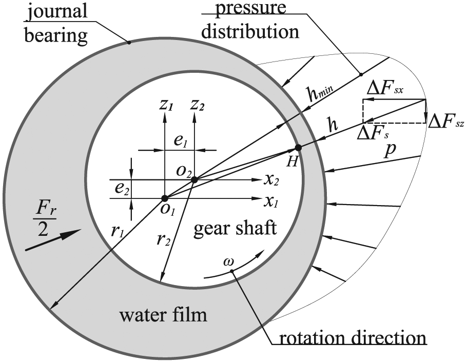
Figure 1 displays the main components of the WHIGP that usually operates at the speed between 1000 and 3000 r/min and the load pressure between 0 and 15 MPa: an internal gear pair (the gear shaft and the ring gear) for the function of fluid delivery, a pair of fillers and floating plates for the function of sealing, and two symmetrically distributed journal bearings for the function of bearing. As shown in Figure 2, the circumference around the gear shaft is divided into three areas by the fillers and the meshing gear pair: the suction area (low pressure), the transitional area, and the discharge area (high pressure). Hence, it can be seen that the gear shaft is subjected to a radial force caused by the circumferential fluid pressure and the meshing force, which needs to be balanced by the water film in the gear-shaft/journal-bearing interface.

Main components of WHIGPs in exploded views.

Division of pressure areas around the gear circumference.
Previously established works concerning the internal gear pumps with fillers (crescent pumps) are quite limited and most of them are focused on the theoretical flow characteristics from kinematic aspects.4–6 Inaguma 7 addressed the friction characteristics between the ring gear and the case via the measurement of the friction torque and the film pressure in the ring-gear/case interface. Rundo and Corvaglia 8 studied the steady-state flow–pressure characteristics and the pressure ripples of the crescent pumps via a lumped parameter model implemented in LMS Amesim. Song et al. 9 investigated the fluid delivery capacity and the trapped volume of the pump using a discretion method, focusing on the influence of the design parameters of the gear pair.
With respect to the gear-shaft/journal-bearing interface in WHIGPs, on one hand, the water film’s carrying capacity is strongly undermined due to its low viscosity, adding to the challenge of the design of the water-lubricated journal bearing without excessive wear in WHIGPs. On the other hand, the water film’s geometry is altered by the surface elastic deformation of the bearing since the material of the bearing is polyetheretherketone (PEEK) with a small Young’s modulus, leading to elasto-hydrodynamic (EHD) lubrication in the interface.
Regarding the water-lubricated journal bearing, previous publications are mainly related to ocean vessels under hydrodynamic lubrication (HL).10–12 Yin et al. 13 investigated the flow field of the journal bearing in water hydraulic axial piston pumps, focusing on the material combination and the structure of the bearing. Ye et al. 14 investigated the dynamic behavior of the bearing-rotor system in seawater desalination pumps, focusing on the influence of the geometric and working parameters on the system stability. However, the aforementioned works are carried out under HL and the bearing surface elastic deformation is not taken into account. Wang et al. 15 conducted an EHD analysis of the water-lubricated journal bearing, suggesting that the bearing surface elastic deformation should be considered if it exceeds 15% of the minimum film height. However, the bearing in Wang et al.’s work is in a relatively greater dimension and yields a smaller eccentricity ratio than those in WHIGPs (radius of bearing in Wang et al.’s work: 40 mm; radius of bearing in WHIGPs: 13.5 mm; eccentricity ratio in Wang et al.’s work: 0.7; eccentricity ratio in WHIGPs: approximately 0.9), and thus, the bearing in Wang et al.’s work is not applicable in WHIGPs. Hence, it can be seen that the peculiarities of the gear-shaft/journal-bearing interface in WHIGPs have not been addressed in previous researches.
As the research extends further theoretically and experimentally, and with the introduction of the micro fabrication techniques, it is realized that it is a promising way to improve the bearing’s performance by applying micro shapes to the bearing surface. 16 Pandazaras and Petropoulos 17 studied the tribological behavior of the convex and concave journal bearings, focusing on decreasing the friction loss. Tala-Ighil and colleagues18,19 conducted an analysis of the texture effects on the bearing characteristics in terms of the carrying capacity and the friction coefficient, focusing on the influence of the texture shape and the texture location. Rasheed 20 studied the influence of the circumferential, axial, and combined surface waviness being applied to the journal bearing liners, focusing on the circumferential and axial waviness numbers. Lee et al. 21 investigated the lubrication characteristics of a textured porous sliding bearing, focusing on the porous layer’s material and the dimple parameters. Noting that these works were conducted under HL, Yu et al. 22 investigated a textured journal bearing, taking the surface elastic deformation into consideration using an EHD model, focusing on the texture arrangements including the texture number and the texture depth.
Apart from applications in the bearing surface, the micro surface shape is also found an effective solution to improving the tribological performance of the lubricating interfaces in hydraulic units, in particular in external gear pumps and axial piston pumps. Thiagarajan et al. 23 investigated the lubricating gap between the gears and the lateral bushes in external gear pumps, with a micro surface linear wedge being added to the lateral surfaces of the gear teeth which enables lower power loss and chance of wear during the working process. Ivantysynova and Lasaar 24 studied the micro geometry on the piston surface in axial piston pumps using the simulation tool CASPAR, focusing on the reduction of the power loss caused by the friction force in the piston/cylinder interface. Moreover, the same research group25,26 proposed several piston surface shapes to reduce the overall energy dissipation caused by the viscous friction and the leakage in the piston/cylinder interface, and to improve the oil film’s carrying capacity in a wide range of operating conditions. Gels and Murrenhoff 27 studied the oil film characteristics between the contoured piston and the cylinder in axial piston pumps, focusing on the optimization of the guidance geometry and the contoured parameters for decreasing the power loss.
It is worth noting that the aforementioned works concerning micro surface shapes on the lubricating interfaces, including the bearing surface and the interface in hydraulic units, are conducted using the mineral oil as the working medium, and the works are mainly focused on the decrease of the power loss caused by the viscous friction. However, when using water as the working medium which has a much lower viscosity (approximately 1/30th to 1/40th of the oil’s), the most crucial aspect is focused on the improvement the water film’s carrying capacity to avoid solid contact and excessive wear in the interface. Meike and colleagues28,29 investigated the micro shapes on the piston surface and found it a workable solution to improving the water film’s carrying capacity in the piston/cylinder interface.
After a thorough literature review, it can be found that the micro surface shapes for the gear-shaft/journal-bearing interface in WHIGPs have not been addressed in previous works. This article makes an attempt to investigate the potentials of the micro shapes on the gear shaft’s surface to improve the water film’s carrying capacity in the gear-shaft/journal-bearing interface by analyzing four different micro surface shapes using an EHD model. The performance of the four different shapes concerning the water film’s carrying capacity is compared to that of the standard straight shape, and the design parameters of the micro shape that performs the best in the proposed shapes are then further discussed under different operating conditions.
EHD model
The EHD model consists of two parts: the film modeling that addresses the film characteristics and the bearing deformation evaluation that addresses the bearing surface elastic deformation and they will be detailed in the following sections.
Film modeling
As shown in Figure 2, the gear shaft is subjected to a radial force

Figure 3 depicts the eccentric position of the gear shaft in the journal bearing in an exaggerated way caused by the radial force. It can be seen that wedged film is formed in the gear-shaft/journal-bearing interface, generating the supporting force to balance the radial force. Due to the small ratio between the film height (micrometer level) and the other two dimensions (film circumference and film length, millimeter level), the film can be unwrapped in a Cartesian reference system (
Eccentric position of the gear shaft in the journal bearing caused by the radial force.

Water film unwrapped on a plane:
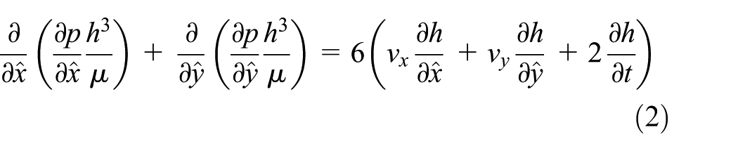
In equation (2), the terms in the right-hand side represent the causes of the film pressure: the hydrodynamic effect and the squeezing effect. The hydrodynamic effect is related to the film height gradient and the gear shaft’s rotation speed

The squeezing effect is related to the time derivative of the film height, which requires an initial evaluation of the film height. Figure 5 depicts the geometrical configuration of gear-shaft/journal-bearing interface, displaying the surface elastic deformation of the bearing and the micro shape on the gear shaft’s surface. Hence, it can be seen that the film height is contributed by three parts: the eccentric position of the gear shaft (h0), the bearing deformation (hp), and the micro surface shape (Δh), as expressed in equation (4)

where h0 is given by the coordinates of the gear shaft’s center (O2) with respect to the bearing’s center (O1), as shown in Figure 3


Geometrical configuration of gear-shaft/journal-bearing interface: eccentric position of the gear shaft, surface deformation of the bearing, and micro shape on the gear shaft’s surface.
In this way, the time derivative of the film height yields

With the boundary conditions that

Bearing deformation evaluation
The bearing surface elastic deformation resulting from the film pressure has a great impact on the film geometry due to being on the same order of magnitude as the film height. Noting that it will take too much time to evaluate the deformation with the direct finite element method at each iteration step during the fluid–structure interaction (FSI) process, an influence matrix approach is adopted to evaluate the deformation, which has been addressed in previous works on journal bearings.31,32
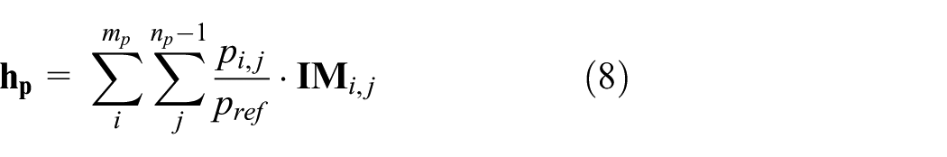
Before executing the influence matrix approach, it needs an initial evaluation of the influence matrix, which corresponds to the bearing surface deformation with a reference pressure being applied to a unit area. Noting that the film mesh number is mp in the circumferential direction and np in the length direction, the bearing’s inner surface can be treated as being divided into mp × (np – 1) faces, and each divided face is a unit area subjected to an individual film pressure.
The bearing surface deformation resulting from the reference pressure can be evaluated with ANSYS Workbench, as shown in Figure 6(a). It can be seen that a displacement constraint is applied to the bearing’s outer surface due to the interference fit between the bearing and the bearing block, following the work addressed by Meng and Chen, 32 and a reference pressure (10 MPa) is applied to the divided face (unit area). The deformation evaluated by ANSYS Workbench can be saved as a text file that stores the numbers, the coordinates, and the directional deformation of the bearing mesh. Noting that the distance between the centerline of the bearing and the mesh on the bearing’s inner surface equals to the radius of bearing bore, the mesh on the bearing’s inner surface can be found using the coordinates of the mesh. The bearing surface deformation corresponds to the radial deformation (deformation in the radial direction) of the found mesh, which constitutes the influence matrix, as shown in Figure 6(b). A peak value of the deformation can be observed at the location (divided face) where the reference pressure is applied, indicating the strong correspondence between the bearing deformation and the applied pressure.

(a) Bearing deformation with the reference pressure (10 MPa) acting on a divided face and (b) the corresponding influence matrix.
Noting that there are mp × (np – 1) divided faces, the number of the influence matrices should be mp × (np – 1), too. Each influence matrix corresponds to the bearing surface deformation by applying the reference pressure to one of divided faces. In this way, based on the superposition principle, the overall bearing deformation can be evaluated by summing all the deformations caused by individual film pressures acting on the divided faces
Micro shape on the gear shaft’s surface
Figure 7 depicts the micro shape designed on the gear shaft’s surface in the shape of sinusoidal waves along the axis direction (y2 direction). Note that it is a convex shape when its derivative at the origin is above zero and it is a concave shape when the derivative at the origin is below zero. Figure 8 displays four different micro surface shapes with different wave numbers: the convex full wave, the concave full wave, the convex half wave, and the concave half wave. Noting that the micro shape is determined by two parameters, namely, the wave amplitude (as) and the wave number (mc), the expression for the full wave can be given by

and the expression for the half wave can be given by


Micro shapes designed on the gear shaft’s surface.

Four different micro surface shapes with different wave numbers: (1) convex full, (2) concave full, (3) convex half, (4) concave half; (I) mc = 0.5, (II) mc = 1, (III) mc = 1.5.
In equations (9) and (10), “+” corresponds to the convex shape while “–” corresponds to the concave shape.
Simulation procedure
Figure 9 presents the simulation procedure of the EHD model for the gear-shaft/journal-bearing interface implemented in MATLAB, which starts with the input parameters including the geometric parameters, the initial values, and the radial force. The key part of the procedure is represented by the FSI process in the first loop, where the bearing surface elastic deformation is evaluated using the influence matrix approach after obtaining the film pressure by solving the Reynolds equation, and the water film height is updated using equation (4) to solve the Reynolds equation again until the convergence of the film pressure (perr converged to 10−5, steps 2–5)


Simulation procedure of the EHD model for the gear-shaft/journal-bearing interface.
Once the FSI process has converged, the supporting force can be obtained using equation (7). The balance of the gear shaft can be given by equation (12) noting that the two journal bearings are symmetrically distributed

It is worthwhile to note that the film pressure and the resulting supporting force are influenced by the eccentric position and the eccentric velocity of the gear shaft. Hence, with respect to a certain time step (a certain eccentric position), equation (12) can be solved by varying the eccentric velocity using the Newton–Raphson approach (Ferr converged to 10−5, steps 6 and 7, loop 2)

Once the balance condition of the gear shaft has been achieved, the new eccentric position of the gear shaft in the new time step can be updated using the obtained eccentric velocity by equation (14) (Δt ∼ 10−5 s, steps 8–10, loop 3)

Because the radial force that the gear shaft undergoes varies periodically, the eccentric positions of the gear shaft will repeat themselves after several cycles of continuous iterations, indicating the convergence of the simulation results, and the simulation procedure stops.
Validation of the model
To validate the proposed EHD model for the gear-shaft/journal-bearing interface, the results by the proposed model are compared with those by Wang et al. 15 and the experimental results by Gao et al. 11 The input parameters in the proposed model were set the same as those in the compared works, in terms of the bearing parameters and the operating conditions.
With respect to the studies by Wang et al., the eccentricity ratio is a pre-set value (0.7), and the load carrying capacity is evaluated under the given eccentricity ratio. By comparison, in the proposed model, the load carrying capacity evaluated by Wang et al. is treated as the radial force, an input of the proposed model (Figure 9), and the eccentricity ratio is evaluated after the convergence of the gear shaft’s eccentric positions using equation (15)
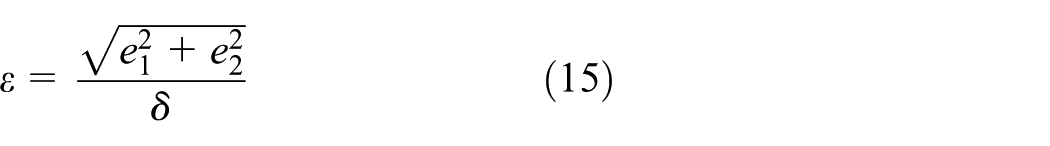
Figure 10 displays the comparisons of the eccentricity ratios by the proposed model and the pre-set value (0.7) by Wang et al. under different speeds and bearing Young’s modulus (500–3000 r/min, 400–1400 MPa). It can be seen that the eccentricity ratios evaluated by the proposed model vary from 0.706 to 0.692, approximately 1% deviation from the pre-set value (0.7) by Wang et al. It is expected that the variations of the eccentricity ratios with different speeds are caused by the cavitation phenomenon in the film, where the sub-ambient pressure is limited to 1 kPa as the work addressed by Pelosi and Ivantysynova. 30
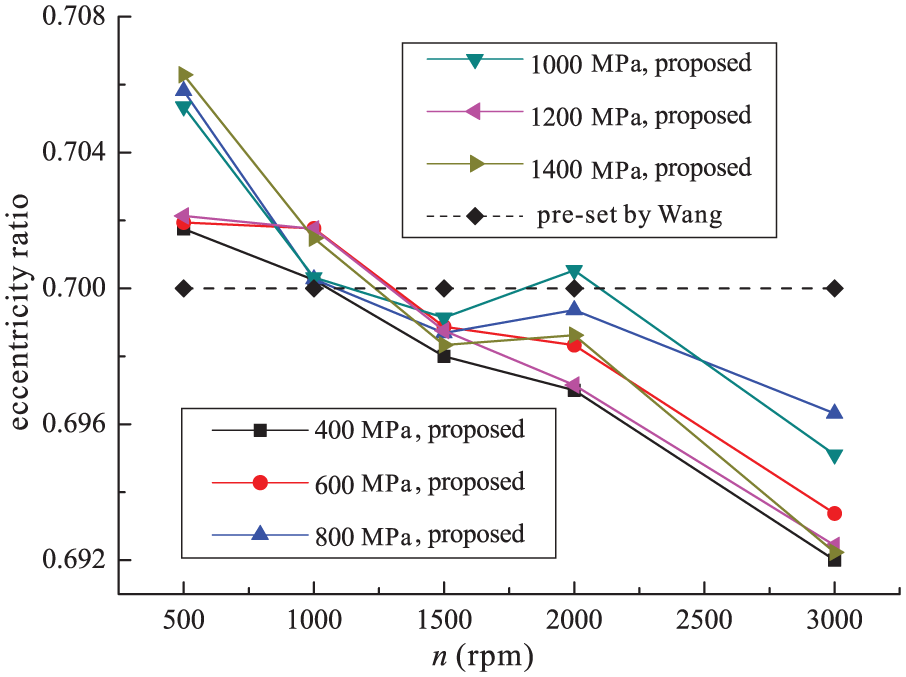
Comparisons of the eccentricity ratios by the proposed model and the pre-set value (0.7) by Wang et al. under different speeds and bearing Young’s modulus.
Figure 11 displays the comparison of the maximum bearing deformation by the proposed model and by Wang et al. under different speeds and bearing Young’s modulus (500–3000 r/min, 400–1400 MPa). It can be seen that the results by the proposed model are in good agreement with those by Wang et al., where the deviation is within 5% when the speed is lower than 1000 r/min and within 2% when the speed is higher than 1500 r/min.
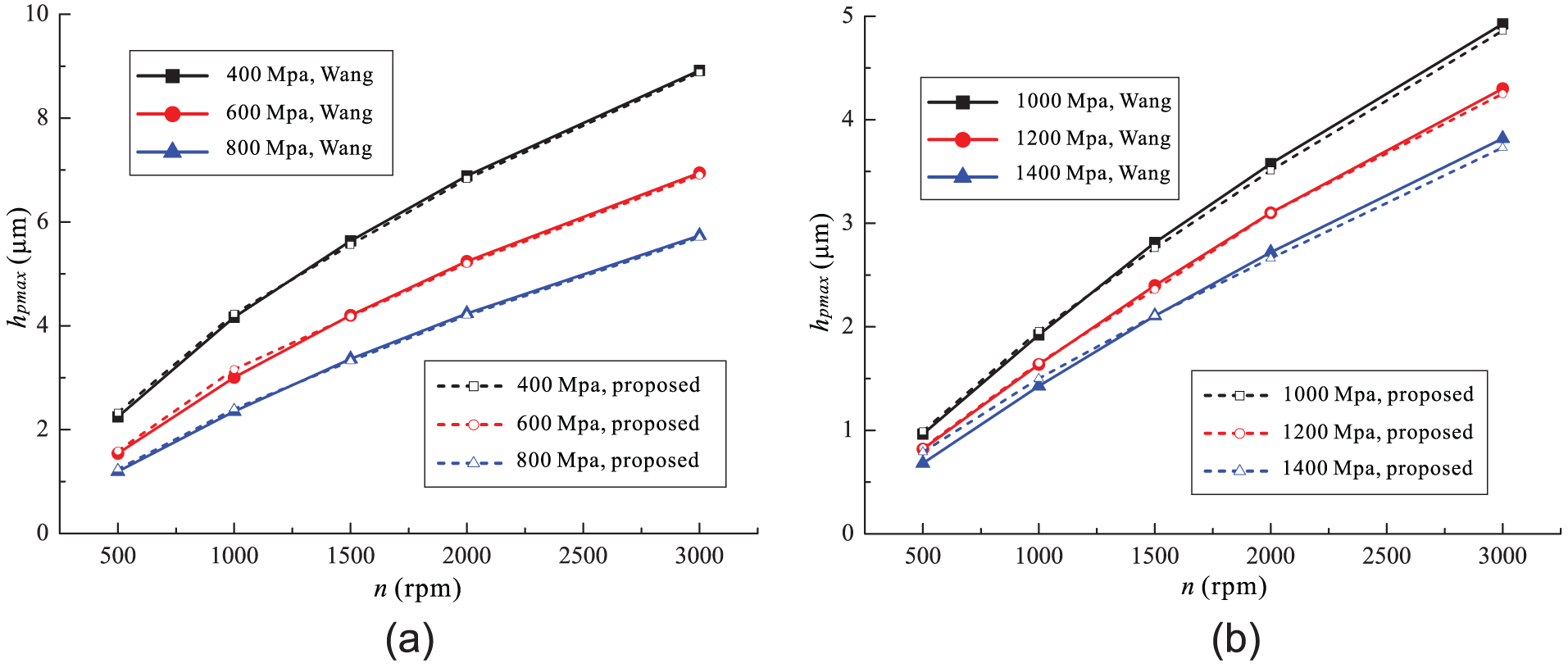
(a) Comparison of the maximum bearing deformation (hpmax) by the proposed model and by Wang et al. under different speeds and bearing Young’s modulus: (a) bearing Young’s modulus: 400–800 MPa and (b) bearing Young’s modulus: 1000–1400 MPa.
With respect to the comparisons with the experimental results by Gao et al., the applied loads in the experiments by Gao et al. are treated as the radial force in the proposed model, and the minimum film height (hmin) can be evaluated after the convergence of the gear shaft’s eccentric positions. Figure 12 displays the comparison of the minimum film height by the proposed model and the experimental results by Gao et al. It can be seen that the results by the proposed model are in the range of the experimental results by Gao et al., except for a 1% deviation under the circumstances of 3000 and 4000 r/min. It is expected that the deviations are caused by the cavitation phenomenon in the film and the measurement uncertainties.

Comparison of the minimum film height (hmin) by the proposed model and the experimental results by Gao et al.
Judging from the analysis above, a good agreement can be observed between the results by the proposed model and those from the published works, justifying the proposed model in the present work.
Results and discussion
Analysis of mesh-independent results
Table 1 displays the main input parameters for the simulation procedure concerning the gear-shaft/journal-bearing interface. With these input parameters, the simulation model runs on the standard straight shape under different mesh numbers (mp × np) to ensure the results to be mesh independent, as depicted in Figure 13. It can be seen that the simulation results, in terms of the eccentricity ratio (ϵ), the minimum film height (hmin), and the maximum deformation (hpmax), vary within 0.2% between 60 × 21, 60 × 41, and 120 × 41. However, the consuming time (t) triples as the mesh number doubles and it rises to approximately 111 h when the mesh is 120 × 41 (an Intel® Xeon® CPU E3-1230 v3, 16.0 GB RAM). Therefore, the selected mesh number in this work is 60 in the circumferential direction and 21 in the length direction.
Main input parameters for the simulation procedure.

PEEK: polyetheretherketone.

Simulation results and consuming time of the standard straight shape under different mesh numbers.
It should be noted that the parameters concerning the radial clearance and the operating conditions may vary for the purpose of analyzing the design parameters of the micro surface shapes under different operating conditions.
Performance of the straight shape
Figure 14 depicts the radial force components acting on the gear shaft in the x and z directions under different load pressures (5 and 15 MPa, n = 3000 r/min). A linear relationship can be observed between the magnitude of the radial force and the load pressure, and the radial force is approximately 7600 N when the load pressure is 15 MPa, making the supporting force of one bearing approximately 3800 N. It can also be observed that all the force components vary periodically at a cycle of roughly 27.7°, which is believed to be because the tooth number of the gear shaft is 13 (360°/13).
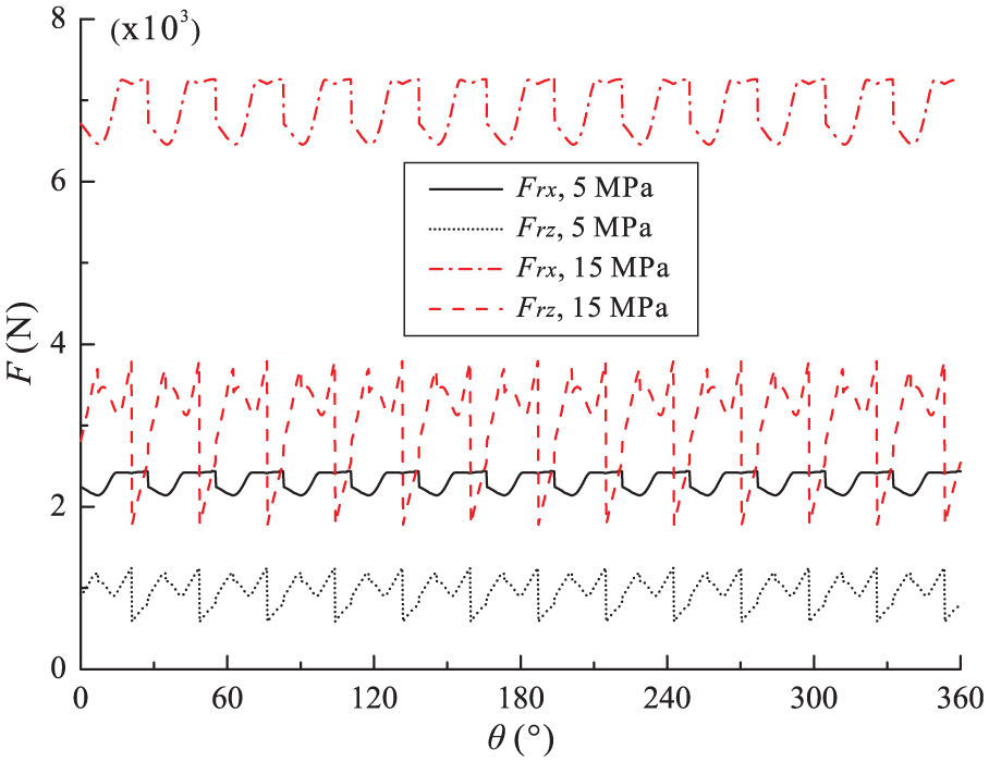
Radial force components acting on the gear shaft under different load pressures (n = 3000 r/min).
Figure 15 depicts the convergence of the gear shaft’s eccentric positions from the initially assumed position. It can be seen that the gear shaft’s eccentric positions converge to a small range and the minimum film height (hmin) can be evaluated accordingly. The minimum film height can serve as a criterion to judge the water film’s carrying capacity, since from the point of view of solid contact and consequent wear phenomenon, greater minimum film height enables less chance of excessive wear.

The convergence of the gear shaft’s eccentric positions from the initially assumed position under different operating conditions (standard straight shape).
Figure 16 depicts the minimum film height (hmin) of the straight shape with respect to the operating conditions where the WHIGP usually operates (1000–3000 r/min, 5–15 MPa). It can be seen that the minimum film height decreases as the operating speed decreases and the load pressure increases, making the condition of 1000 r/min and 15 MPa the most dangerous condition where solid contact is mostly likely to occur. Apart from that the radial clearance (δ) also plays an important role on the minimum film height. It can be observed that when working under 1000 r/min and 15 MPa, the minimum film height yields approximately 0.6 μm when δ is 3 μm, and the minimum film height drops below zero when δ is greater than 7 μm.
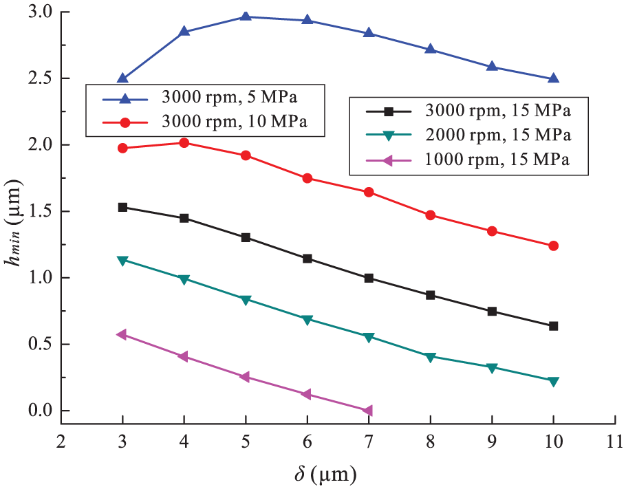
The minimum film height with respect to different operating conditions (standard straight shape).
Performance of the micro shapes
Figure 17 depicts the minimum film height (hmin) with respect to the four different micro surface shapes (convex full, convex half, concave full, and concave half) with elastic bearings (3000 r/min, 15 MPa). Apart from that, Figure 17 also depicts the minimum film height with respect to the standard straight shape with elastic bearings and rigid bearings for the baseline. Figure 18 depicts the load pressure (pl) of the WHIGP when the minimum film height yields 1 μm with respect to the four different micro shapes. Several conclusions can be drawn referring to the two figures:
With respect to the standard straight shape, the minimum film height with elastic bearings is smaller than that with rigid bearings (Figure 17), and the load pressure with elastic bearings is lower than that with rigid bearings (Figure 18), indicating that in WHIGPs where the fixed displacement is applied to the outer surface of the journal bearing, the bearing elastic deformation has a negative effect on the film’s carrying capacity. This is consistent with the works addressed by Yu et al. 22 and Mokhiamer et al. 33
Under the circumstance of mc = 0.5, the convex shape yields a 47% increase while the concave shape yields a 70% decrease in the minimum film height than the straight elastic condition when working under 3000 r/min and 15 MPa (Figure 17). Regarding the load pressure with respect to the minimum film height being 1 μm, the convex shape yields a 54% increase while the concave shape yields a 44% decrease than the straight elastic condition (Figure 18). Hence, it can be seen that the convex shape has a positive effect while the concave shape has a negative effect on the film’s carrying capacity, consistent with the work addressed by Pandazaras and Petropoulos. 17
Under the circumstance of mc ≥ 1, it is clear and consistent that the minimum film height (Figure 17) and the load pressure (Figure 18) become decreasingly lower as mc grows. The micro surface shapes yield smaller minimum film height and lower load pressures than the straight elastic condition except for the convex half shape, indicating that only the convex half shape performs better than the standard straight shape, in agreement with the work addressed by Rasheed. 20

Minimum film height with respect to different micro surface shapes, n = 3000 r/min, pl = 15 MPa, δ = 8 μm, as = 1 μm.

The load pressure (pl) of the WHIGP when the minimum film height yields 1 μm with respect to different micro surface shapes, n = 3000 r/min, δ = 8 μm, as = 1 μm.
Judging from the analysis above, it can be seen that the convex shape with mc = 0.5 (“convex” for short hereafter) performs the best in the proposed micro shapes. Further discussions on the design parameters of the convex shape are performed in the following sections.
Design parameters of the convex shape
Figure 19 depicts the minimum film height (hmin) and the maximum bearing deformation (hpmax) with respect to different wave amplitudes (as) regarding the convex shape. It can be seen that hmin decreases and hpmax increases as the operating speed decreases and the load pressure increases, consistent with the results of the straight shape. With respect to a certain operating condition, it can be observed that hmin exhibits a first increase followed by a decrease as as increases, and hmin achieves its maximum value when as is located between 0.8 and 0.9 times hpmax. It is an effective way to increase hmin by properly setting the value of as, in particular under low operating speed and high load pressure (1000 r/min, 15 MPa), where hmin is below zero for the straight shape (as = 0) and achieves the maximum value of approximately 0.6 μm for the condition of as = 1 μm (in black circles).
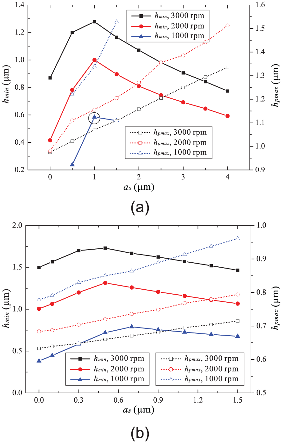
(a) Minimum film height and maximum bearing deformation with respect to different wave amplitudes of the convex shape (δ = 8 μm): (a) pl = 15 MPa and (b) pl = 10 MPa.
The convex shape can be a convex-straight shape, a combination of sinusoidal waves and straight lines, as shown in Figure 20, by introducing a convex ratio λ which is defined as the ratio between the length of the ascending part and the bearing length. It is worth noting that the value of λ should be under 0.5 and a special case of λ = 1 is defined as the standard straight shape for the baseline. Thus, under the circumstance of 0 < λ ≤ 0.5, the expressions for the convex shapes can be written as


Convex shapes composed of sinusoidal waves and straight lines with different convex ratios λ: (1) λ = 1, (2) λ = 1/2, (3) λ = 1/3, (4) λ = 1/4, (5) λ = 1/8, and (6) λ = 0.
As concerns the case of λ = 0, it is also defined as a straight shape, however, the radial clearance decreases to (δ – as). Figure 21 depicts the minimum film height (hmin) under different convex ratios (λ: 0, 1/8, 1/4, 1/3, ½, and 1) and different radial clearances (δ: 6, 8, and 10 μm). It can be seen that hmin decreases as δ increases, consistent with the results of the straight shape. With respect to a certain radial clearance, it can be observed that hmin exhibits a first increase followed by a decrease as λ increases, where hmin achieves its maximum value when λ is 1/3. The convex ratio (λ) is an important design parameter that has a great influence on the performance of the convex shape, in particular under low operating speed and high load pressure (1000 r/min, 15 MPa), where hmin is approximately 0.12 μm for the straight shape (λ = 1, in blue squares) and achieves the maximum value of approximately 0.7 μm for the condition of λ = 1/3 (in blue circles) under the circumstance of δ = 6 μm. Judging from the analysis above, it can be seen that it is a workable solution to increasing hmin and thus lowering the chance of solid contact and consequent wear phenomenon in WHIGPs by applying the convex shape with proper parameters, namely, the wave amplitude, the convex ratio, and the radial clearance.
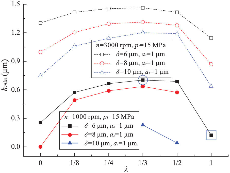
Minimum film height under different convex ratios and different radial clearances (as = 1 μm).
Discussions on the micro shapes
In this section, discussions will be performed with respect to the reasons for the difference of the micro shapes’ performance from the aspects of the film height and the film pressure. Figure 22 depicts the film height field and pressure field of the gear-shaft/journal-bearing interface with respect to the straight shape (elastic bearings, 3000 r/min, 15 MPa, δ = 8 μm). It can be seen that the film geometry exhibits a wavy shape along the

(a) Film height field and (b) film pressure field of the gear-shaft/journal-bearing interface, 3000 r/min, 15 MPa, δ = 8 μm, straight shape, elastic bearings.
Figure 23 depicts the load pressure (pl) of the WHIGP, the film pressure peak (pmax), and the film height (hE and hM) when the minimum film height (hmin) yields 1 μm with respect to different bearing conditions (straight rigid, straight elastic, convex elastic, and concave elastic). With respect to the straight shape condition, it can be seen that the bearing elastic deformation leads to a greater hM, preventing the film pressure peak (pmax) from increasing, and this is believed to be the reason why the bearing elastic deformation leads to a decrease in the film’s carrying capacity. With respect to the convex shape and the concave shape, it can be seen that the convex shape leads to a smaller hM and a greater pmax while the concave shape leads to a greater hM and a lower pmax. This is believed to be the reason why the convex shape has a positive effect while the concave shape has a negative effect on the film’s carrying capacity.

The load pressure (pl) of the WHIGP, the film pressure peak (pmax), and the film height (hE and hM) when the minimum film height (hmin) yields 1 μm with respect to different bearing conditions (n = 3000 r/min, δ = 8 μm, as = 1 μm).
Figure 24 depicts the minimum film height lines with respect to different wave amplitudes (as) of the convex shape; the maximum bearing deformation (hpmax) is approximately 1 μm (3000 r/min, 15 MPa, δ = 8 μm, mc = 0.5, λ = 1/3). It is clear and consistent that the convex shape leads to an increase in hE and a decrease in hM as the wave amplitude increases. Moreover, it can be observed that when as is smaller than hpmax, the minimum film height (hmin, in ellipses) is located at the ends of the minimum film height line (hE), which increases as as increases; when as is greater than hpmax, hmin (in rectangles) is located in the middle of the line (hM), which decreases as as increases. This is believed to be the reason why as should be maintained 0.8–0.9 times hpmax.

Minimum film height lines with respect to different wave amplitudes (as), 3000 r/min, 15 MPa, δ = 8 μm, mc = 0.5, λ = 1/3.
Conclusion
This article describes an approach for improving the water film’s carrying capacity in the gear-shaft/journal-bearing interface in WHIGPs by introducing micro shapes to the gear shaft’s surface. An EHD model for the gear-shaft/journal-bearing interface is proposed in this article for the analysis of the performance of the micro surface shapes, and the model is validated by comparison with the results from other research groups.
Four different micro shapes are analyzed in the present work, and simulation results suggest that the convex shape has a positive effect while the concave shape has a negative effect on the water film’s carrying capacity. Additionally, further discussions on the design parameters of the convex shape indicate that it is workable to increase the minimum film height and thus lowering the chance of solid contact and consequent wear phenomenon in WHIGPs. The wave amplitude should be 0.8–0.9 times the maximum deformation of the bearing, and the convex ratio should be 1/3.
In addition to the convex shape discussed in the present work, there should be more micro shapes that are able to improve the water film’s carrying capacity in the gear-shaft/journal-bearing interface in WHIGPs. The EHD model proposed in this article can be used as a tool for predictions of the micro shapes’ feasibilities and further discussions on the design parameters without repeated trial-and-error procedure.
Some aspects have not been taken into consideration in the present EHD model especially with respect to the lubricating surface roughness, and these will be discussed in the future development of the model. Additionally, the micro shapes will be machined on gear shaft in WHIGPs for further experiments on WHIGPs in the next research phase.
Footnotes
Appendix 1
Acknowledgements
The authors are grateful to the anonymous reviewers and the editor for their constructive comments.
Handling Editor: Ismet Baran
Declaration of conflicting interests
The author(s) declared no potential conflicts of interest with respect to the research, authorship, and/or publication of this article.
Funding
The author(s) disclosed receipt of the following financial support for the research, authorship, and/or publication of this article: The authors would also like to acknowledge the support of the National Natural Science Foundation of China (grant no. 51521064) and Science and Technology Innovation Team of Independent Design Projects of Zhejiang Province (grant no. 2013TD01).