
Abstract
The crack initiation and propagation phases of the fatigue life of a plate specimen with a center hole are analyzed. The local transient stress–strain relationship is investigated by means of finite element simulations with a nonlinear kinematic hardening model. Modifications are proposed for the conventional notch analysis with the strain-life methodology considering the effect of mean stress relaxation and strain ratchetting. With the proposed modifications, the crack initiation life at the notch is less dependent on the load ratio, as it is in classic analysis methods. The initiated cracks are further investigated with fracture mechanics methods to evaluate total fatigue life. The eXtended finite element method and analytical formulas are applied to obtain the crack path and stress intensity factors, the results of which are in excellent agreement. Propagation life is estimated with the NASGRO crack-growth model fitted on the experimental results.
Keywords
Introduction
A frequent goal of simulation engineers is to determine the service life of a structural component. Since accurate multiaxial total life approaches have not been established, total fatigue life is considered the sum of crack initiation and propagation life. This two-stage approach has been used by de Jesus et al. 1 for the fatigue assessment of riveted and bolted joints. A probabilistic version of the two-stage approach has been applied for a notched geometry by Correia et al. 2
Promising steps are continually being made in the direction of a unified model for material fatigue, such as the work of Liu et al., 3 utilizing damage mechanics to describe the damage accumulation process. Kim et al. 4 developed a fatigue model using a cycle-dependent cohesive zone law, where the reduction of fracture energy and degradation of stiffness describe the material fatigue. Łukaszewicz 5 used the criterion of averaged structural microdamage resulting from local slips for the fatigue life estimation of test specimens under tension and torsion.
The fatigue analysis of notched components is still a heavily researched area with many fundamentally different competing approaches. Fracture mechanics approaches offer robust and industrially established descriptions for the propagation of long cracks, while the analysis of microstructurally (∼<0.1 mm) and mechanically (∼<1 mm) short cracks is continually developing. Chapetti and Guerrero 6 proposed an integrated fracture mechanical approach for the analysis of blunt and sharp notches. Madia and Zerbst 7 employed the cyclic R-curve method, whereas the crack driving force of a small crack is compared to the resistance force incorporating crack closure effects to determine the fatigue limit of notched specimens and model surface roughness. Silva et al. 8 compared the results of finite element method (FEM) analyses with the virtual crack closure technique (VCCT) and the displacement extrapolation (DE) method with the experimentally measured stress intensity factors (SIF) under mixed-mode crack-growth conditions.
Crack nucleation is often modeled with continuum mechanics. Different approaches are being developed for the stress–strain evaluation near stress concentrators. The most prevalent are the critical distance, 9 highly stressed-volume, 10 and gradient-based 11 methods. A strain-based description is commonly applied, since the local stresses are usually above the elastic limit. New multiaxial approaches are being developed based on the critical plane method using local strain energy.12,13 The probabilistic method of Zhu et al. 14 is capable of considering the usual scatter found in material parameters in the multiaxial low-cycle fatigue (LCF) assessment. Special attention has been given lately to the fatigue assessment of components operating under high temperatures.15,16 Horas et al. 17 successfully combined the modal superposition technique with the local strain-life approach for the elastic stress–strain computation of a structural system under dynamic loads.
The mean stress effect significantly influences fatigue life, and new models are being developed for a more accurate description. Ince 18 recently proposed a new mean stress fatigue model based on distortional strain energy that provides better correlation with experimental data for cast iron, steel, and aluminum than the classic approaches (Smith–Watson–Topper (SWT), Morrow). The strain energy-based mean stress correction model of Zhu et al. 19 offers a more accurate description of the experimental results based on the analysis of 13 datasets.
The effect of mean stress relaxation and strain ratchetting on the fatigue behavior of metallic materials has been studied by numerous researchers.20–22 Zhu et al. 23 recently developed a new fatigue life prediction model with the introduction of the mean ratchetting strain rate to quantify ratchetting effects. Despite its confirmed significance, the mean stress relaxation effect is still not considered in many analyses using local strains as the main input parameter.24–28
Probabilistic approaches are gaining popularity due to their ability to handle the unavoidable uncertainties found in the mechanical properties of engineering materials. They have been successfully applied for the assessment of crack initiation,14,29 propagation,30–33 and two-stage total life analysis.2,34
The aim of this study is to model the crack initiation and propagation process in a notched plate specimen from the experiments of Björkblad. 35 Crack initiation life is calculated with the Coffin–Manson relationship, whereas nonlinear finite element analysis (FEA) and the unified notch rule (UNR) from Meggiolaro et al. 36 are applied for local strain computation. Special attention is given to the mean stress relaxation and strain ratchetting effect, which leads to a change in the local R-ratio. The computed initiation life is considered to lead to a 1-mm crack length. The propagation life is analyzed with the well-established NASGRO crack-growth model, 37 with numerically and analytically calculated SIF.
Nodular cast iron material and experimental details
The experimental results derive from the work of Björkblad 35 and concern a ferritic nodular cast iron (NCI) solution hardened by high silicon content, which is classified as grade ISO 1083/JS/500-10. 38 The ISO 1083/JS/500-10 classification has greatly improved machinability compared to the ferritic–pearlitic grade ISO 1083/JS/500-7 with comparable mechanical properties. The chemical composition is shown in Table 1, and the material properties are summarized in Table 2.
Chemical composition of silicon hardened ferritic NCI. 35

NCI: nodular cast iron.
Material properties of silicon hardened ferritic NCI. 35
NCI: nodular cast iron.
The fatigue test specimen geometry is shown in Figure 1. The local stress concentration effect of the hole at the center can be described with a theoretical stress concentration factor Kt of 3. The 50-mm width of the specimen assures uniform stress distribution and a long crack path. The 4-mm thickness provides a close to membrane stress state, minimizing bending effects. It can be concluded from the work of Björkblad 35 that plane stress and plane strain SIF solutions are very close for this geometry.

Fatigue test specimen geometry. 35
Constant load was used during the tests, which is beneficial for crack propagation testing and also common for industrial components. From the hole at the center, the crack initiated after 30,000–35,000 cycles with σmin = −25 MPa to σmax = 225 MPa sinusoidal loading. Initiated cracks were 0.2–0.3 mm in length and propagated beyond the plastic zone using the same load level as the following crack propagation testing before the crack rate measurements.
Crack propagation rate measurements were made in the work of Björkblad 35 at R0 and R0.8 load levels. The load ratios were chosen so the results were affected by crack closure (R0) and to obtain approximately closure-free results (R0.8).
Crack initiation
As the first step for strain-life assessment, the local stress–strain relationship has to be carefully analyzed, since it is expected to be transient due to the cyclic loading. Cyclic loading conditions are often asymmetric for structural components of industrial assemblies.
At geometrical discontinuities, the remote stresses and strains are described and the local stress–strain relationship is the result of the geometrical conditions and the material behavior, leading to combined strain ratchetting with mean stress relaxation. With the accumulation of the plastic strain, the local mean stress is expected to gradually relax and stabilize with a zero-mean stress. 39
Numerical modeling of cyclic plasticity
Linear elastic and nonlinear FE calculations were conducted with ANSYS Mechanical 17.2 for the local stress and strain computation. The analysis model is shown in Figure 2, with the model coordinate system, boundary conditions, and applied load. The testing volume of the plate fatigue test specimen is considered in the analysis utilizing the symmetry to the Y-axis. Two-dimensional plane stress simplification was applied considering the plate-like geometry of the test specimens. Mesh convergence was verified by comparing the well-known theoretical stress concentration factor (Kt) of 3 for the infinite plate under tension with a center hole and the linear elastic

2D plane stress FE model for linear and nonlinear stress–strain analysis of the fatigue specimen.
The elastic–plastic behavior at the notch tip was analyzed with the Chaboche nonlinear kinematic hardening model,
40
as it can accurately model cyclic loading effects, such as ratchetting and shakedown. Two kinematic models have been superimposed to accurately describe the cyclic evolution of the mean stress under force controlled loading. Model parameters
Monotonic and cyclic material parameters for silicon hardened ferritic NCI. 41

NCI: nodular cast iron.
Parameters for the Chaboche nonlinear kinematic hardening model for silicon hardened ferritic NCI.

NCI: nodular cast iron.
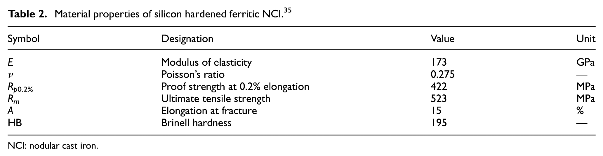
In accordance with the findings of Wang and Rose, 39 the simulation results in Figure 3 show the mean stress relaxation effect in the local tensor Y normal stress–tensor Y total strain relationship. The mean stress reached zero in less than 40 simulated cycles in both cases, leading to a symmetric stress–strain relationship. In addition to the R-0.11 loading of the fatigue test itself, a cyclic loading condition with an R0.5 load ratio was simulated to illustrate the local material behavior.
Simulated stress–strain relationship for the test specimen at R-0.11 and R0.5.
The mean stress relaxation and strain ratchetting effects are the result of the accumulation of plastic strain in each load cycle, which is confirmed by the analysis results shown in Figure 4.

Accumulation of the tensor Y local plastic strain at the location of the maximum tensor Y stress.
Estimating local stress–strain behavior with the UNR
The UNR from Meggiolaro et al. 36 can be applied to compute the elastoplastic (EP) stress–strain at notches under proportional multiaxial loading conditions. For fatigue design, fast and automatable solutions for local EP stress–strain computations are significant, which has led to the formulation of several similar approaches, such as Kilambi and Tipton 42 and Ince and Bang. 43
For a simple monotonic uniaxial case, UNR can be expressed in the following form

where

The effective notch constraint factor is given by
where
With the calibrated value of
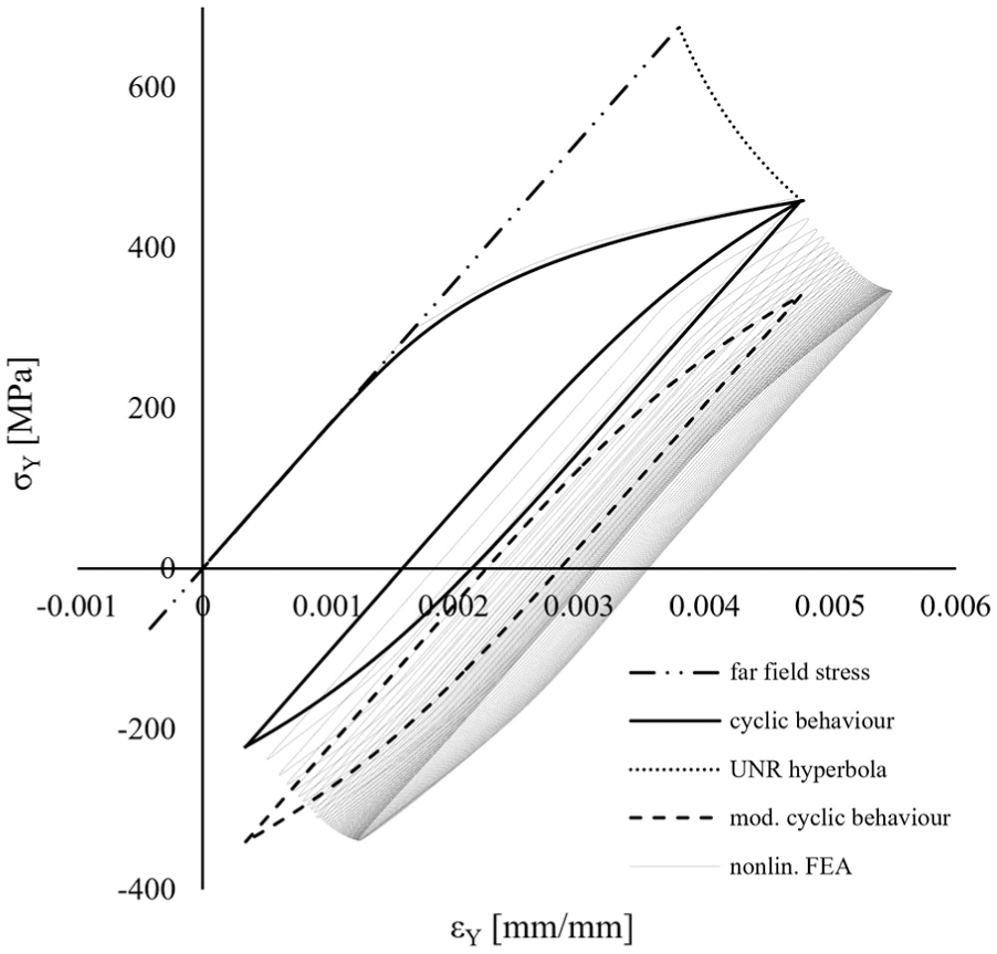
Analysis with the modified UNR method compared to the FE results.
Initiation life calculation
Fatigue crack initiation life of notched components is often assessed with strain-based methods, since the local stresses are often above the elastic limit at sharp notches. The Coffin–Manson equation is widely used to describe the low-cycle fatigue behavior of metallic materials

where
Due to the accumulation of plastic strain cycle-by-cycle, the local mean stress converges to zero, which is the case for any arbitrary asymmetric loading. Hao et al. 21 proposed an empirical model for mean stress relaxation, which is later introduced in the Morrow model with a nonlinear damage model, leading to the following formula

where crack initiation life

where
In the analysis model for the experimental procedure where the calculated initiation life with the model from Hao et al. 21 is 60,509 cycles, with the analysis of the stabilized stress–strain relationship, 61,176 cycles are obtained. The transient phase can be neglected with an estimated error of 1.1% in lifetime for the given scenario. This result is easy to interpret and the life spent in the transient phase is negligible compared to the total initiation life. Even for a highly asymmetric R0.5 loading, the mean stress relaxation occurs swiftly (<50 cycles) according to the nonlinear FE analysis. The change in stress and total strain amplitude is negligible over the mean stress relaxation phenomenon.
Based on these results, it is reasonable to assume that the input parameters for the strain-life analysis should be evaluated after stabilization around the zero-mean stress. Based on this assumption, the same correction can be made for the analytical results obtained with UNR. With the shift of the cyclic loop into a zero-mean stress position, the strain and stress amplitudes are in good agreement with the FE results. The less than 5% difference in the calculated strain amplitudes leads to a larger difference in the calculated initiation life; however, analytical results remain on the safe side. The proposed modified UNR method has the advantage of being significantly faster and automatable over the EP-FE solution, which is important for industrial application. Result accuracy is greatly improved compared to the UNR method in its original formulation. An EP-FEA assessment is still advised for multiaxial notch analysis with high accuracy requirements.
The results of the different computational methods are compared in Table 5. The calculated crack initiation lives are obtained through strain-life assessment of the resulting stresses and strains with the parameters in Table 6.
Comparison of nonlinear FEA and UNR results with test results from Björkblad. 35

FEA: finite element analysis; UNR: unified notch rule; SWT: Smith–Watson–Topper.
Manson–Coffin parameters for silicon hardened ferritic NCI. 41

NCI: nodular cast iron.
The nonlinear FEA results were evaluated with the Coffin–Manson relationship (equation (4)) after reaching zero-mean stress. The UNR method is applied in its original form, leading to a non-zero-mean stress condition. In this case, the SWT 45 parameter was used to account for the mean stress effects. For the modified UNR method, the cyclic loop has been translated into a zero-mean stress position where the simple Coffin–Manson relationship can be applied for life calculation.
With the proposed modification, the crack initiation life at the notch is less dependent on the R-ratio, as it is in the traditional strain-based notch analysis methods. This statement can be synthesized with two well-established findings: the strain-life curves of smooth specimens are R-ratio independent in the lower regime of fatigue life and the effective threshold SIF range corresponding to microstructural crack initiation is also R-ratio independent.
Crack propagation
Due to the simple specimen geometry, both numerical (eXtended finite element method (X-FEM)) and closed-form solutions were applied and compared for the SIF calculation along the crack path in the crack propagation phase.
Calculating stress intensity factors with X-FEM
The X-FEM approach was originally formulated by Belytschko and Black 46 and was later developed by Moës et al. 47 to its current mathematical formulation. It has been applied in numerous studies with promising results on fatigue crack path prediction and SIF calculation.48–50 The X-FEM method has the significant advantage of preserving the initial mesh over the classic FE solutions for crack growth. The idea was to introduce proper discontinuities within the element formulation, so that the mesh does not have to adapt to the crack path. Displacement modes of the standard FEs are enriched with additional discontinuous displacements to capture the stress-front singularity. Mesh refinement is not necessary to capture the effect of the discontinuities, which leads to solvable problems in three-dimensional bodies with reasonable computation times due to the relatively course meshing providing converged solutions. Crack propagation is simulated by an update of two different level sets, which specify the position of the crack surface inside an element.
The X-FEM computation for crack path prediction and SIF range calculation was carried out with the XFEM Crack Initiation and Propagation ACT App for ANSYS Mechanical 17.2. Besides the structured quadrilateral mesh shown in Figure 6, the model setup is the same as the one for the stress analysis. The crack was initiated in the FE model within the element with the highest elemental maximum principal stress and then propagated according to the maximum circuumferential stress criterion. The singularity enrichment size is 0.2 mm. Figure 7 shows the displaced mesh to qualitatively illustrate the propagating crack tip and the reduction of the load carrying cross-section of the specimen. The comparison of the computed SIF range with the closed-form solution for an R0 loading with
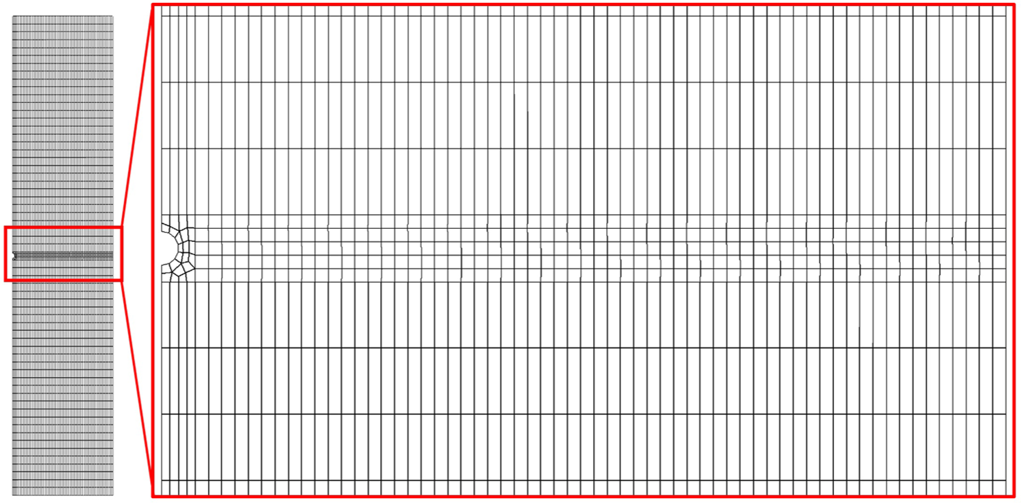
Quadrilateral structured mesh for X-FEM crack propagation analysis.

Displaced mesh illustrating the crack propagation process with X-FEM analysis.

Analytical calculation and X-FEM solution for the stress intensity factor range versus crack length
Calculating SIF
The SIF solution for the center cracked plate specimen from Tada et al.
51
is utilized as a reference for comparison with the numerical computation. The mode I SIF range
where

where
Life prediction with the NASGRO model
With knowledge of the SIF range along the crack path for the different (R0 and R0.8) loading scenarios analyzed, propagation life can be calculated with the application of a crack-growth equation describing the relationship between the crack-growth rate
The NASGRO crack-growth equation
37
can accurately describe the crack propagation rate in the transition zones at the threshold and critical crack-growth regime. The effect of different load ratios is modeled using the crack opening function
According to the NASGRO model, the crack propagation rate is given by

where
where
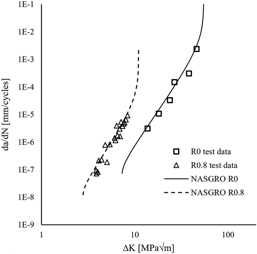
Parameter identification for the NASGRO model was achieved with a curve fitting process employing the least-squares method on the experimental data from Björkblad. 35 The NASGRO model with the parameters summarized in Table 7 offers a good description of the experimental crack-growth data shown in Figure 9.
Parameters for the Chaboche nonlinear kinematic hardening model for silicon hardened ferritic NCI.

NCI: nodular cast iron.
Experimental
The incremental lifetime analysis (numerical integration of the crack-growth rate along the crack length) predicts 400,000 cycles for R0 and 25,500 cycles for an R0.8 tensile loading with

Predicted crack length as a function of load cycles.
Conclusion
FE analysis with the nonlinear kinematic hardening model identified on the cyclic flow curve of the investigated material can appropriately model the mean stress relaxation and strain ratchetting phenomena at notches.
The modified Morrow model with a nonlinear damage model rule from Hao et al. 21 is suitable to precisely determine the mean stress relaxation effect on crack initiation life within the strain-life methodology.
According to the authors, fatigue notch analysis should be performed with the separation of the initiation and propagation phases of fatigue life. For the sake of simplicity, in engineering calculations, the strain-life analysis should be performed on the stabilized stress–strain loop at the notch tip, which can be estimated with the shift of the initial loop into a zero-mean stress position. The stress–strain hysteresis results obtained with the modified UNR method are significantly closer to the EP-FE solution than the results obtained with the original UNR approach.
To determine the initial stress–strain loop, the UNR method from Meggiolaro et al. 36 has been employed with success in this uniaxial case under plane stress conditions.
With the proposed modification of the strain-life notch analysis, the initiation life becomes less dependent on the local R-ratio. This phenomenon is also supported by the fact that the effective threshold SIF range corresponding to microstructural crack initiation is also R-ratio independent. 53
X-FEM offers an accurate solution for the crack path and SIF computation in structural components for general cases at reasonable computational costs. The possible difficulties with convergence near the critical SIF range are acceptable because propagation life is insensitive to the near phase III behavior.
Footnotes
Handling Editor: Shun-Peng Zhu
Declaration of conflicting interests
The author(s) declared no potential conflicts of interest with respect to the research, authorship, and/or publication of this article.
Funding
The author(s) disclosed receipt of the following financial support for the research, authorship, and/or publication of this article: The recent study and publication were realized within the Knorr–Bremse Scholarship Program supported by the Knorr–Bremse Rail Systems Budapest.