
Abstract
For a seamless two-speed transmission specially equipped in electric vehicles, the global trajectory optimization problem of the overlapping shift process with multiple stages and complex path/point constraints is investigated in this article. The overlapping shift principle and the dynamic models in each phase are also demonstrated in detail. The parameters to evaluate the shift quality are analyzed and then introduced into the objective function and constraints, respectively. The jerks in process and at the key moments have been distinguished and selected as the path and point constraints, respectively. Moreover, considering the joint characteristics of the torque phase and the inertia phase, the trajectory optimization problems in the above two phases are summarized as a multi-stage global trajectory optimization problem. Then, Legendre pseudo-spectral method is used to transfer the multi-stage global trajectory optimization problem into a nonlinear programming problem for numerical solutions. Finally, the effectiveness and feasibility of the multi-stage global trajectory optimization method have been verified through the comparison of the optimal shift trajectories under different conditions with that obtained by the piecewise trajectory optimization method.
Keywords
Introduction
Usually, electric vehicle (EV) is equipped with only a single-speed transmission for the wide torque characteristics of the traction motor and the strict restrictions on the size, mass, and cost of the transmission system. 1 Recent studies2,3 consider that the adoption of multi-speed transmission in the driveline system of EVs has significantly great improvements on the dynamic and economic performances. However, it must be pointed out that the introduced multi-speed transmission should be able to accomplish seamless shifts to be competitive with the single-speed transmission for EVs. 4
As well known, conventional automated mechanical transmission (AMT) exhibits the problem of torque interruption during shifts, which has seriously bad impacts on the shift smoothness. 5 In order to achieve seamless shifts, several kinds of transmissions, such as dual-clutch transmission (DCT) and hydraulic automatic transmission (AT) which shift based on the overlapping between the friction components (such as the friction clutch and brake), have been introduced in the driveline system of EVs.6,7 So far, DCT and AT have not been successfully popularized in the driveline system of EVs owing to the high cost and significant control complexity. In order to provide seamless shifts for EVs and simultaneously keep the structures of the transmission and the corresponding actuators compact, some overlapping friction components are suggested to be replaced with simpler and mechanically more robust switch components (such as one-way clutch, synchronizer, and dog clutch).8–10
The overlapping shift process between the friction components (or between the friction component and the switch component) is usually divided into two phases: torque phase and inertia phase. 11 Nowadays, the linear feed-forward control strategy is always applied in the torque phase, while major focus is directed toward the trajectory optimization (i.e. control strategy) in the inertia phase. 12 Recently, extensive studies on the trajectory optimization in the inertia phase have been carried out and could be summarized up as the following two main routes. On one hand, several kinds of empirical trajectories of the mismatch speeds of the on-coming clutch have been proposed, and some feedback controllers, such as proportional integral derivative controller,13,14 back-stepping controller, 15 sliding mode controller, 16 and model predictive controller, 17 are used to track these referenced mismatch speeds. On the other hand, the trajectory optimization problem is considered as an optimal control problem (OCP) with the increasing requirements of the shift quality. Some optimal algorithms, such as linear quadratic Gaussian,18,19 the principle of the minimum, 20 and dynamic programming, 21 are used to obtain the optimal overlapping shift trajectories.
In the above studies, the trajectory optimizations in the torque phase and the inertia phase are usually carried out independently for the dynamic equations in the two phases are different and the multi-stage variable OCP is hard to be overcome through traditional optimal control algorithms. Moreover, the complex path and point constraints have also caused the complexity and difficulty of the multi-stage OCP. However, the torque phase and the inertia phase are tightly coupled with each other, and the dynamic characteristics of the previous phase have great influences on that of the latter phase. Usually, the simple combination of the traditional piecewise trajectory optimizations of the two phases does not represent the precise global optimization of the overall overlapping shift process. In order to adequately optimize the overlapping shift trajectories to get the best compromise of the shift qualities in the torque phase and the inertia phase, the trajectory optimization problems in the two phases are more reasonable to be synthesized as an integral OCP with multiple variable stages and also complex constraints.
Recently, some highly efficient numerical solving methods for OCPs, such as pseudo-spectral method (PM) 22 and Haar wavelet–based method,23,24 have been provided as a novel approach for solutions by transferring the original differential constraints into algebraic constraints. PM has been extensively used in many engineering fields, such as the reusable launch vehicle approach and landing trajectory optimization 25 and the trajectory optimization of the accelerating strategy for the vehicles with multi-speed transmission. 26 Compared with other traditional numerical solutions (such as shooting method), PM provides the great advantages of fewer solving parameters, faster convergence, and larger radius of convergence. 27 Furthermore, its co-state mapping theorem, in which the co-state variables could be mapped by the Karush–Kuhn–Tucker (KKT) multipliers of the coupling nonlinear programming (NLP) problem, lays the solid foundation for its reasonability and accuracy. 28 Legendre PM (LPM), as an important member of the conventional PMs, is more suitable than other PMs (such as Gauss PM, Radau PM, and Chebyshev PM) to solve the specific OCPs with point constraints at the initial and terminal moments. 29
Therefore, for a seamless two-speed transmission with pretty compact packaging, which is designed by Sorniotti et al.4,8 and based on the overlapping between a friction clutch and a one-way clutch, LPM is used in this article to solve the multi-stage global trajectory optimization problem of the overlapping shift process. The rest of this article is organized as follows: in section “Dynamic modeling,” the overlapping shift principle and the dynamic models in each phase are presented in detail. The multi-stage global trajectory optimization problem of the overlapping shift process and its numerical solving method based on LPM are presented in section “Multi-stage global trajectory optimization method.” The comparison of the numerical results obtained by the proposed multi-stage global trajectory optimization method and the conventional piecewise trajectory optimization method is exhibited in section “Numerical results.” Finally, section “Conclusion” presents the conclusions.
Dynamic modeling
Overlapping shift principle
The seamless two-speed transmission consists of a friction clutch, a one-way clutch, a locking ring of the one-way clutch, actuators of the friction clutch and the locking ring, a first gear couple, and a second gear couple. The schematic of the driveline system of the EV with the two-speed transmission is illustrated in Figure 1. The motor torque is transmitted by the one-way clutch while in first gear, and by the friction clutch while in second gear.

Schematic diagram of the driveline system of the electric vehicle with the seamless two-speed transmission.
During upshift, the locking ring of the one-way clutch is pre-disengaged and the friction clutch engages gradually. Part of the motor torque is transferred from the one-way clutch to the friction clutch. When the one-way clutch torque decreases to 0, the one-way clutch disengages and the upshift process is switched from the torque phase to the inertia phase. The speeds of the driving and driven parts of the friction clutch are approaching until the friction clutch is locked up at the end of the inertia phase. When the friction clutch is locked up, the upshift is finished.
The downshift in power-on is approximately regarded as a reverse process of the upshift. First, the pressing force of the friction clutch is decreased gradually until the friction clutch’s transmissible torque is lower than its transmitting torque. Then, the friction clutch slips into the dynamic friction condition and the speed of the driving part of the one-way clutch is accelerated to be synchronous with the speed of its driven part. When the speed synchronization of the one-way clutch is achieved, the one-way clutch is engaged and the downshift process is switched from the inertia phase to the torque phase. Finally, the motor torque is transferred from the friction clutch to the one-way clutch with the sequentially disengagement of the friction clutch in the torque phase. When the friction clutch is completely disengaged, the downshift process in power-on is finished. On account of the space limitation, only the dynamic characteristics of the driveline system and the trajectory optimization problem of the overlapping upshift are analyzed in this article.
The simplified diagram of the dynamic characteristics of the driveline system during the upshift implemented in the condition of constant driver torque demand (DTD) is illustrated in Figure 2, where t 1 and t 2 are the start and end of the torque phase during upshift, respectively; t 3 is the end of the inertia phase during upshift.
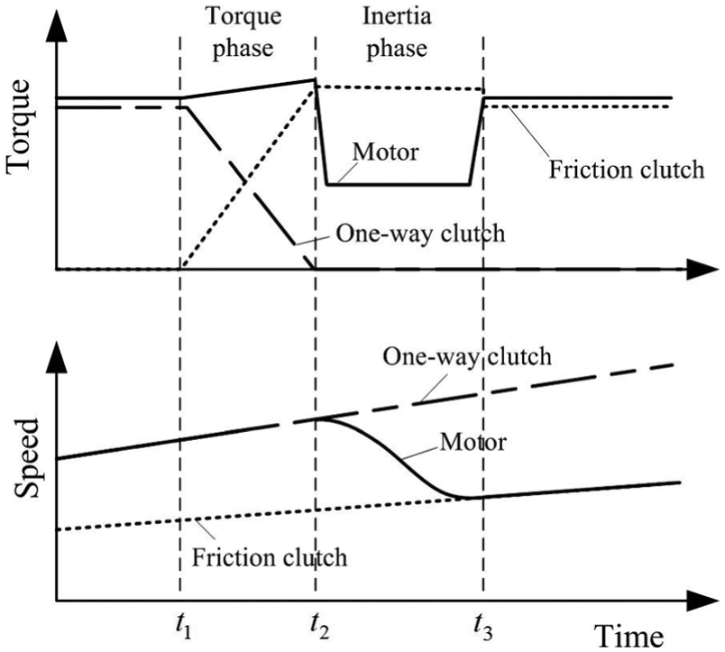
Simplified diagram of the dynamic characteristics of the driveline system during the upshift in the condition of constant DTD.
Dynamic equations
The simplified dynamic model of the driveline system especially for the trajectory optimization problem is established based on the following assumptions:
The motor output shaft, intermediate shaft, and wheel shaft are regarded as the rigid bodies with concentrated inertia.
The stiffness and damping characteristics of the drive shaft and the motor output shaft are neglected as they are the secondary effects’ relation to the trajectory optimization which is the focus of this article.
The influences of environmental factors on the working states of the transmission components are also neglected.
The simplified dynamic model of the EV’s driveline system with the two-speed transmission is presented in Figure 3.
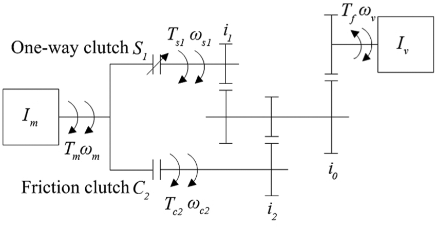
Simplified dynamic model of the electric vehicle’s driveline system.
The dynamic equations during the overlapping upshift are presented as follows
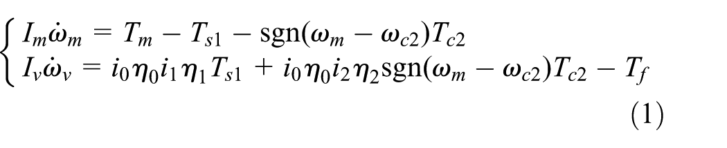
where sgn is a symbolic function and its expression is presented as

The motor torque could be interpolated from a lookup table as a function of the DTD and the motor rotational speed and presented as

When the locking ring of the one-way clutch is disengaged, the one-way clutch engages or disengages automatically according to the mismatch speed of its driving and driven parts owing to its special physical structure. So, the one-way clutch is modeled as an ideal switch component and presented as

Based on the assumption that the driving and driven parts of the friction clutch obey the Coulomb friction law, the friction clutch torque is modeled as

The equivalent resistance torque Tf (including the rolling friction torque, aerodynamic drag torque, and road slope torque) converted at the wheel shaft is regarded as constant for the shift duration is short enough, and it is presented as

Before or after the overlapping upshift, the EV runs stably in first or second gear. In first or second gear, the motor speed is strictly coincident with the speed of the driven part of the one-way clutch (or the friction clutch), and the one-way clutch (or the friction clutch) is transmitting the corresponding inertia moment. Based on the above analyses, the dynamic equations of the driveline system in first or second gear can be derived from equation (1) and presented as

where k = 1 or 2, and the expression for the equivalent moment of inertia of the whole driveline system converted at the wheel shaft in first or second gear is given by

State-space model
For the uniformity of the state-space models in both the torque phase and inertia phase, the state and control variables are selected as

The dynamic equations in the torque phase and the inertia phase are then transformed into the terms of state-space models. In the following equations, superscripts 1 or 2 on the state variables, control variables, or state functions indicate that the variables or functions belong to the torque phase or the inertia phase, respectively.
Torque phase
In the torque phase, the one-way clutch is engaged and the speeds of its driving and driven parts are strictly consistent. The motor torque is gradually transferred from the one-way clutch to the friction clutch. The state-space model in the torque phase is presented as

where

Moreover, the equality constraint of the speeds of the driving and driven parts of the one-way clutch must be satisfied in the torque phase and is presented as

Inertia phase
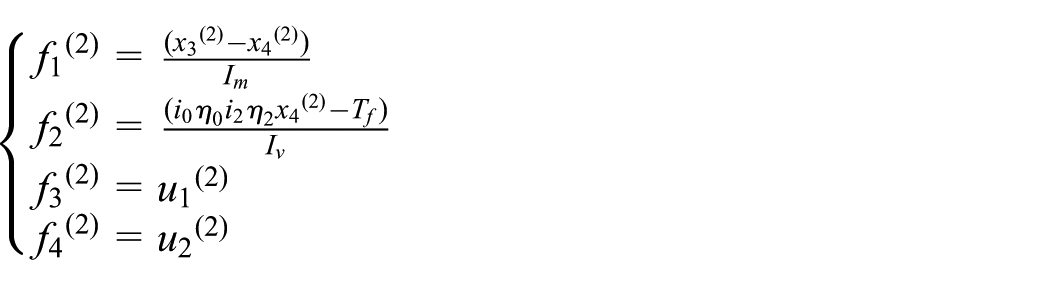
During the inertia phase, the one-way clutch is already disengaged and the kinematic ratio from the motor speed to the transmission output shaft speed changes from i 1 to i 2. The state-space model in the inertia phase is presented as

where
Multi-stage global trajectory optimization method
As presented in the introduction, the trajectory optimization problem of the overlapping shift process, which includes multiple variable phases, is more reasonable to be regarded as an integral multi-stage global OCP to get the best compromise of the shift qualities of the torque phase and inertia phase. Then, LPM is adopted in this section to transfer the multi-stage global OCP into a coupling NLP problem for fast numerical solutions.
Multi-stage global trajectory optimization problem
The parameters such as the vehicle jerk, which is defined as the derivative value of the vehicle’s longitudinal acceleration, and the friction work are usually used to evaluate the shift quality (such as the shift smoothness and the abrasion of the friction clutch). 9 It must be pointed out that there are two kinds of jerks during the overlapping shift. One is caused by the continuous change in the motor torque or the friction clutch torque in process, whereas the other is caused by the sudden transition from dynamic friction condition to static friction condition of the friction clutch at the speed synchronization moment (i.e. the end of the inertia phase). It is suggested in Lu et al. 30 and Zhao et al. 31 that the maximum amplitude of the jerk, rather than the integral of the quadratic item of the jerk, is usually used as the evaluation index of the shift smoothness. So the jerks during the overlapping upshift are required within the permissible range, and the requirements of the jerks in process and at the speed synchronization moment are introduced into the path constraints and point constraints, respectively.
The objective function, path constraints, point constraints, and joint constraints of the integral multi-stage global trajectory optimization problem of the overlapping upshift are described as follows.
Objective function
The weighted sum of the friction work and the impacts of the control variables in both the torque phase and the inertia phase is selected as the objective function and presented as
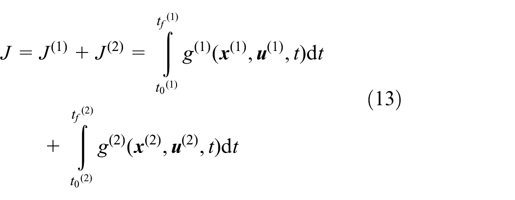
where
The weighted coefficients of the friction work and the impacts of the control variables could be adjusted according to different preferences of the shift quality.
Path constraint
First, in order to keep the jerks in process of the torque phase and the inertia phase within the permissible range, the inequality path constraint C 1 is introduced and presented as

where the jerks in process of the torque phase and inertia phase are expressed as

Second, with respect to the dynamic characteristics of the actuators of the motor and the friction clutch, the inequality path constraint C 2 is applied on the control variables u 1 and u 2

Next, in order to ensure the motor torque within the torque capacity of the motor, the inequality path constraint C 3 on the state variable x 3 is introduced and presented as

where

Finally, given the speeds of the driving and driven parts of the one-way clutch are strictly consistent in the torque phase, the equality path constraint C 4 is introduced and presented as

Point constraint
First, the torque transferred by the one-way clutch becomes 0 at the transition moment between the torque phase and the inertia phase on the basis of the overlapping shift principle. So, the equality point constraint

Second, at the end of the inertia phase, the speeds of the driving and driven parts of the friction clutch should be synchronous and the torque transferred by friction clutch should be larger than the motor’s output torque to avoid the friction clutch slipping again. Then, the equality point constraint


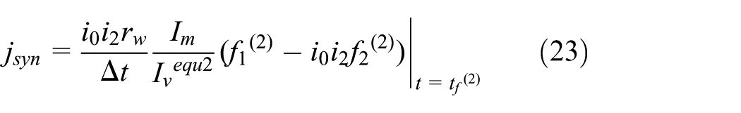
Meanwhile, the jerk at the speed synchronization moment of the friction clutch (i.e. the end of the inertia phase) is also required within the permissible range. So, the inequality point constraint

where the jerk at the speed synchronization moment of the friction clutch, 32 which is caused by the sudden transition from dynamic friction condition to static friction condition of the friction clutch, is presented as
Moreover, the motor torque should be consistent with the value corresponding to the current DTD and motor speed at the end of the inertia phase. So, the equality point constraint

Finally, in order to ensure the immediacy of the overlapping upshift, the inequality point constraint

Joint constraint
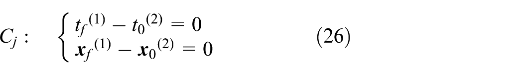
At the transition moment between the torque phase and the inertia phase, not only the time variable but also the state variables must be continuous. So, the joint constraint
Based on the above analyses of the objective function, path constraints, point constraints, and joint constraints, the integral multi-stage global trajectory optimization problem of the overlapping upshift is summed up as

LPM
The proposed multi-stage global trajectory optimization problem for the overlapping upshift has not only multiple variable stages but also complex path and point constraints and is hard to be overcome through traditional optimal control algorithms. LPM is adopted to transfer the multi-stage global trajectory optimization problem into an NLP problem for fast numerical solutions. The main steps of the transformation are described as follows. Similarly, superscript p (equals 1 or 2) on the following variables and functions indicates that they belong into the torque phase or inertia phase.
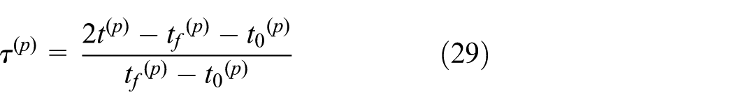
Step 1: time mapping
The collocation points of LPM are Legendre–Gauss–Lobatto (LGL) points, which are the roots of the first derivative of the Legendre orthogonal polynomials of N degrees, and distributed in the normal time interval [−1, 1]. The Legendre orthogonal polynomial of N degrees is defined as

So first the time intervals of the torque phase
Step 2: discretization
The nodes of the LPM consist of the LGL collocation points, the initial point, and the terminal point and are denoted by


The Lagrange interpolating polynomial is presented as

Step 3: transformation of the state equations
Based on the Lagrange interpolation of the state variables, the differential of the state variables at the nodes could also be approximated by the differential of the Lagrange polynomials and presented as

The differential matrix

So, the state equations in the torque phase and the inertia phase could be transformed into the following algebraic equations at the corresponding nodes
Step 4: approximation of the objective function
The integral term of the objective function is approximated through the Gauss–Lobatto (GL) numerical integration and presented as
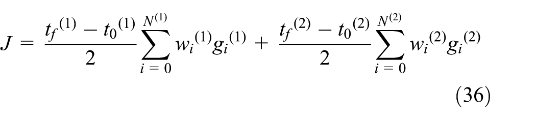
where the weighted coefficient of the GL numerical integration is described as

The path constraints in the torque phase and the inertia phase are then acted on the approximations of the control and state variables at all the nodes in the corresponding phase. While the point constraints and joint constraints are just acted on the boundary nodes of the torque phase and the inertia phase.
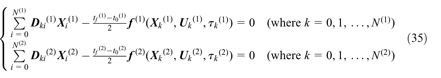
In summary, the above multi-stage global trajectory optimization problem is transformed into the following NLP problem through LPM

The variables to be optimized in the above NLP problem are the approximations of the state and control variables at the nodes of the torque phase and inertia phase, the switching moment between the torque phase and the inertia phase, and the terminal moment of the inertia phase. The number of the variables to be optimized is presented as

The professional NLP problem’s solver SNOPT, 33 which is developed based on the sequential quadratic programming algorithm, is used for numerical solutions of the above NLP problem. As the approximations of the state and control variables at the nodes have been solved successfully, the optimal trajectories of the state and control variables during the overlapping upshift could then be obtained through the Lagrange interpolating method.
Numerical results
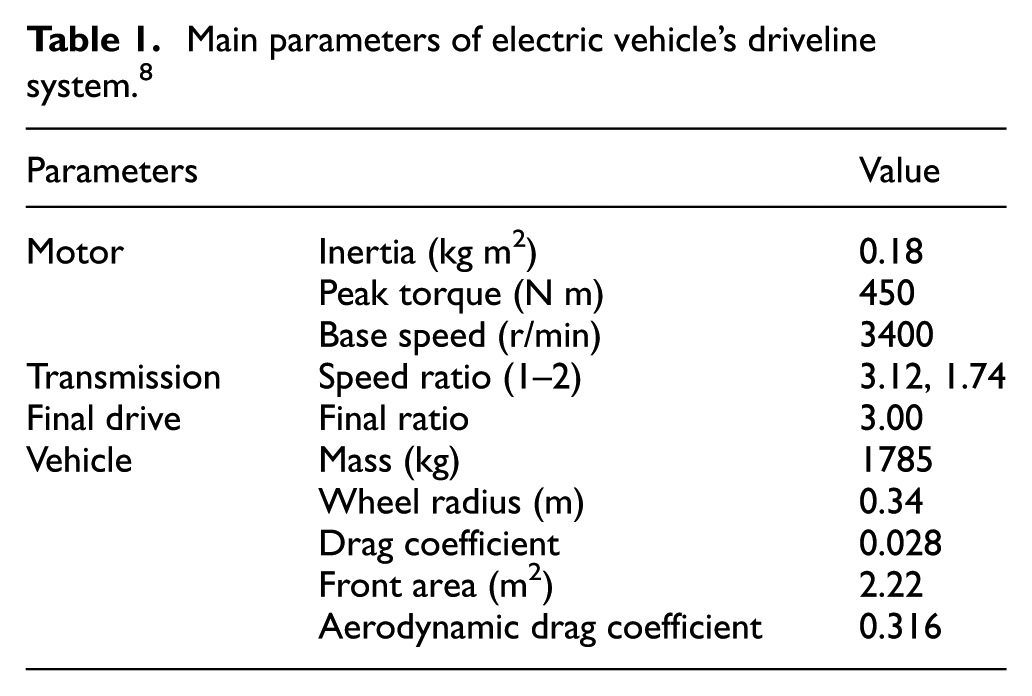
To verify the feasibility and effectiveness of the proposed multi-stage global trajectory optimization method, the optimal upshift trajectories obtained using #1 method (the proposed multi-stage global trajectory optimization method) and #2 method (the conventional piecewise trajectory optimization method 7 ) are compared in the following section. The trajectory optimization problems in the torque phase and the inertia phase are constructed as two independent OCPs and then solved separately when #2 method is used. For a better comparison of #1 and #2 methods, the objective function, path constraints, and point constraints of the OCPs in the torque phase and the inertia phase are established based on the same principle proposed in section “Multi-stage global trajectory optimization method.” While the constraint of the overall shift duration are equally acted on the durations of the torque phase and the inertia phase for the switching moment of the two phases is unable to be determined before the trajectory optimization. The main parameters of the driveline system of the EV are derived from an actual EV and shown in Table 1.
Main parameters of electric vehicle’s driveline system. 8
Comparison of the optimal upshift trajectories in the constant-torque region
Figure 4 demonstrates the optimal trajectories obtained using both #1 and #2 methods for the upshift at a DTD of 40% and carried out when the vehicle speed is 30 km/h and also in the constant-torque region of the motor. The weighted coefficients of the friction work and the impacts of the control variables in the objective function are set as kw = 1 × 10⁻⁴, ku1 = 5 × 10⁻⁶, and ku2 = 5 × 10⁻⁶, and the constraints of the vehicle jerk amplitude and the shift duration are set as jp = 2 m/s3 and ts = 0.7 s.
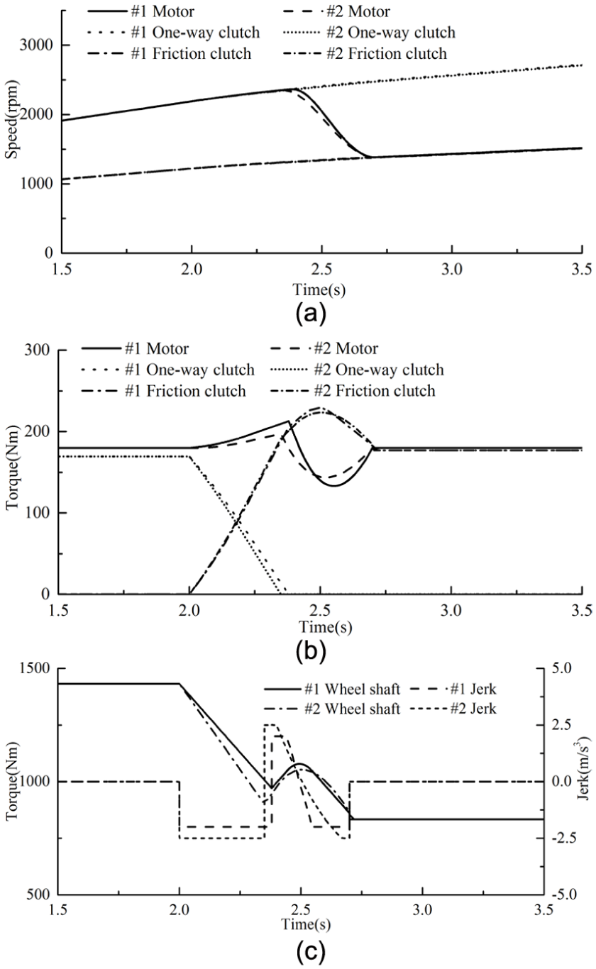
Optimal upshift trajectories at the DTD of 40% and vehicle speed of 30 km/h.
The optimal trajectories (#1) have been successfully obtained using #1 method and shown in Figure 4. As shown in Figure 4(b), the torque phase is actuated by the engagement of the friction clutch at 2.0 s. During the torque phase, the motor torque is increased in harmony to compensate the torque reduction in the wheel shaft. When the one-way clutch torque decreases to 0 at 2.38 s, the upshift process is transformed from the torque phase to the inertia phase. In the first half of the inertia phase, a large decrease in the motor torque has been caused to accomplish the quick speed synchronization of the friction clutch. However, the torque difference between the motor and the friction clutch decreases rapidly in the last half of the inertia phase so that the accelerations of the driving and driven parts of the friction clutch approach close enough to decrease the jerk at the speed synchronization moment. As shown in Figure 4(a), the speed of the motor is synchronous with the speed of the friction clutch at 2.7 s and then the friction clutch is locked up. The locking up of the friction clutch implies the end of the whole upshift. It can also be seen in Figure 4(c) that the wheel shaft torque changes smoothly from 1432 N m (first gear) to 833 N m (second gear), and the jerks in process and at the speed synchronization moment are strictly kept within the permissible range (from −2 to 2 m/s3).
However, the optimal upshift trajectories under the same constraint of the jerk amplitude (2 m/s3) are unsuccessfully solved using #2 method as the obtained optimal control variable u1 vibrates violently in the torque phase and it causes the jerks exceed the permissible range distinctly (i.e. the path constraint of the jerk in the torque phase has been broken badly). The main reason for the above phenomenon is that the constraints of the vehicle jerk and the shift duration are pretty strict, and the switching moment of the torque phase and the inertia phase is unable to be adjusted automatically in #2 method.
The constraint of the vehicle jerk amplitude is then broadened to 2.5 m/s3 in #2 method. The optimal shift trajectories (#2) with the larger constraint of jerk amplitude have also been solved successfully and included in Figure 4. As shown in the optimal trajectories (#2) in Figure 4(c), the jerks in process and at the speed synchronization moment are also kept within the broadened constraint (from −2.53 to 2.5 m/s3).
The main shift qualities obtained using #1 and #2 methods in Figure 4 are listed in Table 2. The mean and maximum jerk amplitudes obtained using #1 method have separately 5.1% and 20% reductions compared with that obtained using #2 method. The friction work obtained using #1 method has a 4.7% increase compared with that obtained using #2 method for the constraint of vehicle jerk has been broadened in #2 method. It must be pointed out that the values of the objective function obtained using the two methods in the present situation are incomparable for the constraints of the vehicle jerk amplitude are different.
Comparison of the main shift qualities obtained using #1 and #2 methods in the constant-torque region.

DTD: driver torque demand.
Comparison of the optimal upshift trajectories in the constant-power region
The optimal trajectories obtained using #1 and #2 methods for the upshift at a DTD of 40% and carried out when the vehicle speed is 75 km/h in the constant-power region of the motor are demonstrated in Figure 5. The weighted coefficients of the friction work and the impacts of the control variables in the objective function are set as the same as that in Figure 4. The permissible jerk amplitude in Figure 5 is set as a relatively smaller value (1 m/s3) for the upshift is carried out in the constant-power region of the motor and the wheel shaft torque is kept generally unchanged before and after the upshift. The constraint of overall shift duration in Figure 5 is broadened to 1 s for the vehicle speed is larger and the permissible jerk amplitude is smaller than that in Figure 4.

Optimal upshift trajectories at the DTD of 40% and vehicle speed of 75 km/h.
As shown in Figure 5, both the optimal trajectories have been successfully obtained using #1 and #2 methods. As shown in Figure 5(a), the speed of the motor is synchronous with the speed of the the friction clutch at 5 s and 4.97 s respectively when #1 and #2 method are used, and then the friction clutch is locked up. The locking up of the friction clutch implies the end of the whole upshift. As shown in Figure 5(b), all the change rules of the motor torque, one-way clutch torque, and friction clutch torque obtained using #1 and #2 methods obey the same tendencies which prompt the quick torque transfer from the one-way clutch to the fiction clutch in the torque phase and speed synchronization of the friction clutch in the inertia phase. Moreover, the jerks in process and at the speed synchronization moment obtained using #1 and #2 methods are kept within the permissible range.
The main shift qualities obtained using #1 and #2 methods in Figure 5 are listed in Table 3. The mean jerk amplitude obtained using #1 method is 0.74 m/s3 and has a 20.4% reduction compared with that obtained using #2 method. It could also be seen in Figure 5(c) that the torque hole of wheel shaft (#1) is relatively smaller than that obtained using #2 method. Even though the friction work obtained using #1 method has a 9.9% increase, the value of the objective function has an 8.3% reduction compared with that obtained using #2 method.
Comparison of the main upshift qualities obtained using #1 and #2 methods in the constant-power region.

DTD: driver torque demand.
Conclusion
The trajectory optimization problems in the torque phase and the inertia phase of the overlapping shift of a two-speed seamless transmission are synthesized as an integral multi-stage global trajectory optimization problem to get the best compromise of the shift qualities of the two phases. LPM is adopted to overcome the proposed multi-stage global trajectory optimization problem with not only multiple variable phases but also complex path and point constraints for numerical solutions. The effectiveness and feasibility of the multi-stage global trajectory optimization method have been validated through the comparison with the conventional piecewise trajectory optimization method. The comparison indicates that the proposed global trajectory optimization method could not only coordinate the shift qualities in the torque phase and the inertia phase synthetically but also be more adaptable under pretty strict path and point constraints. Moreover, the above results show that the multi-stage global trajectory optimization method proposed in this article could be used to perform effective improvements of the dynamic characteristics of the overlapping shift of the two-speed seamless transmission.
Further research on this topic is under development at the National Local Engineering Laboratory of Automobile Parts Technology in South China University of Technology in the following two aspects:
Aspect I: Designing a robust multi-loop feedback controller34,35 to reject the disturbances, noise, and uncertainties in the modeling of the multiple input and multiple output (MIMO) systems. For example, estimating the transmitting torque of the one-way clutch to determine the switching moment between the torque phase and the inertia phase in an even more precise way.
Aspect II: The overlapping shift process is divided into more phases (such as torque phase, inertia phase, and torque resuming phase) to obtain a more precise multi-stage global optimal shift trajectory.
Footnotes
Appendix 1
Handling Editor: Hamid Reza Karimi
Declaration of conflicting interests
The author(s) declared no potential conflicts of interest with respect to the research, authorship, and/or publication of this article.
Funding
The author(s) disclosed receipt of the following financial support for the research, authorship, and/or publication of this article: This work was supported by the National Natural Science Foundation of China (grant no. 51405087), the Natural Science Foundation of Guangdong Province (grant no. 2016A030313517), and the Fundamental Research Funds for the Central Universities (grant no. 2015ZZ086).