
Abstract
Along with the advent of four-wheel-drive electric vehicles, plenty of control strategies have been proposed for such vehicles to coordinate the torque distribution between the four driving wheels. However, how the torque distribution fundamentally affects stability and handling and how the stability/handling characteristics shed light on control system design still require more in-depth investigation. In this article, the stability and handling performances of such electric vehicles are investigated by means of CarSim–Simulink co-simulation. Based on the stability/handling characteristics, a controller is designed to actively adjust the front–rear torque distribution, and another controller is devised to actively tune the left–right torque distribution. The effectiveness of the proposed controllers is verified through CarSim–Simulink co-simulation. The simulation results indicate that the former controller improves stability especially on slippery road surfaces, and the latter controller not only enhances handling in common driving scenarios but also guarantees stability in critical driving conditions.
Introduction
In recent years, four-wheel-drive electric vehicles with independent driving motors have become a research focus due to the high flexibility and capability in terms of vehicle chassis control. 1 First, the independent motors are controlled individually, and as a result, the torque outputs of the four motors can be different. This advantage enables almost arbitrary torque distribution between the four wheels and, in turn, significantly benefits the dynamic performance of electric vehicles under various driving scenarios. Besides, electric motors generate both positive and negative torques to regulate the vehicle motions and do not necessarily slow down the vehicle, while the traditional braking-based chassis control systems inevitably cause intrusive deceleration. 2 Furthermore, the swift, accurate and measurable torque generation provided by the electric motors significantly facilitates the design and implementation of chassis control systems. 1
Topics regarding torque distribution have been widely discussed in the vehicular literature. Klomp and Thomson 3 looked into the influence of longitudinal acceleration and front–rear drive force distribution on the lateral grip and steering characteristics for four-wheel-drive vehicles, with equal longitudinal forces distributed to the left and right wheels. Tahami et al. 4 introduced a fuzzy logic driver-assist stability system for four-wheel-drive electric vehicles. This system assists the driver with path correction and, in turn, improves stability and safety. To take full advantage of four-wheel-drive electric vehicles, Zou et al. 5 developed a tyre longitudinal force optimisation method in which two target indexes are proposed to enhance vehicle stability and manoeuvrability. De Novellis et al. 6 investigated various cost functions for the optimisation problem of wheel torque allocation, for a four-wheel-drive electric vehicle with independent motors. They concluded that cost functions based on tyre slip minimisation can result in better control performance than those based on energy efficiency. In the series of works proposed by Mutoh and colleagues,7–10 the driving characteristics of front and rear wheel independent drive (FRID)–type electric vehicles (i.e. one electric motor drives two front wheels, and the other motor drives the rear wheels) are investigated. The focus of these works was on the fail–safe performance of the proposed FRID vehicles, compared with electric vehicles equipped with independent driving motors for each driving wheel.
It is worth pointing out that sliding mode control is one of the most commonly used control technique for torque distribution control, due to its multi-fold advantages. Fu et al. 1 proposed a sliding mode-based direct yaw moment control method for electric and hybrid vehicles with independent motors. This method employs a new switching function design to simultaneously track the desired yaw rate and desired sideslip angle. Chen et al. 2 proposed a hierarchical direct yaw moment controller for in-wheel motor electric vehicles. In this work, the upper controller determines the desired yaw moment using sliding mode control, and the lower controller distributes differential longitudinal forces according to the desired yaw moment. Alipour et al. 11 proposed a modified and online-tuned sliding mode control scheme for a four-wheel-drive electric vehicle, which is able to track the desired vehicle motion when an in-wheel motor fault occurs.
Recently, integrated control of torque distribution systems and other chassis control systems has become a research focus in this field, aiming to achieve better comprehensive performance by coordinating multiple systems. Mashadi and Majidi 12 designed a multilayer integrated controller of active front steering and direct yaw moment control. The high-level control provides the corrective steering angle and corrective yaw moment, while the low-level control regulates the wheel slip and motor torque. Similarly, Her et al. 13 proposed an integrated chassis control algorithm of differential braking, front–rear traction torque and active roll moment, aiming to maximise driving velocity and enhance lateral stability in cornering. Besides, Ono et al. 14 proposed an integrated control algorithm for four-wheel-distributed steering and four-wheel-distributed traction/braking vehicles to minimise the work load of each tyre.
The above works have tackled torque distribution issues from different points of view, aiming to achieve some specific control objectives in terms of stability/handling enhancement. It is well known that accurate and in-depth knowledge of the control plant is one prerequisite for achieving high control performance. However, the fundamental stability/handling characteristics of four-wheel-drive electric vehicles, namely, how the torque distribution between the four driving wheels fundamentally influences stability and handling, have not received sufficient attention yet. As a result, the control strategies designed on the basis of electric vehicle stability/handling characteristics have not been thoroughly discussed.
To address this issue, two major tasks are completed in this study:
The stability and handling performances of four-wheel-drive electric vehicles with different front–rear and left–right torque distribution ratios are investigated by means of CarSim–Simulink co-simulation. Also, how different front–rear and left–right torque distribution ratios affect vehicle stability and handling is analysed.
Based on the stability/handling characteristics, a front–rear torque distribution controller and a left–right torque distribution controller are designed to regulate the vehicle motions, thereby enhancing the stability and handling of four-wheel-drive electric vehicles. The effectiveness of these two proposed controllers is validated by means of CarSim–Simulink co-simulation.
The rest of this article is organised as follows: section ‘Effects of torque distribution on stability and handling of four-wheel-drive electric vehicles’ discusses the effects of torque distribution on vehicle stability and handling performances, section ‘Design of torque distribution controllers’ demonstrates the design processes of the front–rear and left–right torque distribution controllers, section ‘Simulation verification’ presents the simulation validation results for the proposed torque distribution controllers, and section ‘Conclusion and discussion’ concludes this article.
Effects of torque distribution on stability and handling of four-wheel-drive electric vehicles
The front–rear torque distribution and left–right torque distribution play different roles in the driving characteristics of electric vehicles. Based on the existing literature, the following general rules can be summarised:15,16
When the front wheel steer angle is small, the shift of driving torque to the front axle intensifies understeer (or attenuates oversteer), and the shift to the rear axle intensifies oversteer (or attenuates understeer);
The shift of driving torque to the left (or right) driving wheel produces a clockwise (or counter-clockwise) yaw moment. When this moment is consistent with the direction of turning, oversteer is intensified (or understeer is attenuated), otherwise understeer is intensified (or oversteer is attenuated).
However, the above rules only provide a general idea of the torque distribution effects. In this work, in-depth simulation studies using CarSim and Simulink are conducted, under several typical driving conditions commonly used in vehicle stability and handling evaluation. The simulation results shown in this section will provide details of the fundamental stability/handling characteristics of four-wheel-drive electric vehicles and shed light on the controller designs introduced in the next section.
Simulation platform
The commercial vehicle dynamic simulation software CarSim 17 is employed as our simulation platform. The built-in D-class sedan model in CarSim is adopted, and its power train is modified to simulate a four-wheel-drive electric vehicle. In particular, we build a power train of a four-wheel-drive electric vehicle (with four independent motors) in Simulink to replace the original four-wheel-drive power train in CarSim. By this means, the accurate control of the driving torque applied to each wheel becomes available.
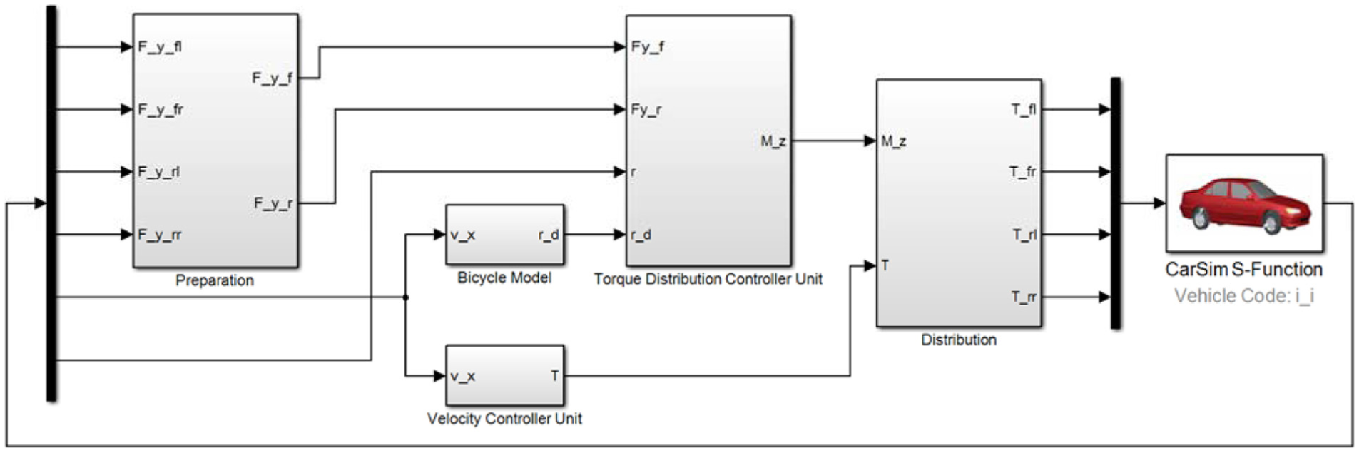
Figure 1 demonstrates the electric vehicle power train model we established for CarSim–Simulink co-simulation. In this model, the vehicle longitudinal speed

The four-wheel-drive power train model established for CarSim–Simulink co-simulation.
Simulation studies under typical driving conditions
Effects of front–rear torque distribution
The simulation conditions are configured as follows:
18
five fixed front–rear torque distribution ratios are chosen for the simulation studies, which are 0:100, 25:75, 50:50, 75:25 and 100:0. The road friction coefficient
Based on the above settings, three vehicle manoeuvres are simulated:
Tuning on a high
Tuning on a low µ (0.2) road surface with an acceleration of 0.5 m/s2;
Tuning on a low µ (0.3) road surface with an acceleration of 1 m/s2.
For all above manoeuvres, the simulated vehicle starts accelerating from rest, and the employed steering wheel angle is shown in Figure 2.

The steering wheel angle for the constant turning manoeuvre.
Figures 3 and 4 show the yaw rate responses and vehicle paths on a high
The yaw rate responses with

The vehicle paths with
This phenomenon can be explained as follows: since the road friction coefficient
Figures 5 and 6 demonstrate the yaw rate responses and vehicle paths on a low

The yaw rate responses with
The vehicle paths with
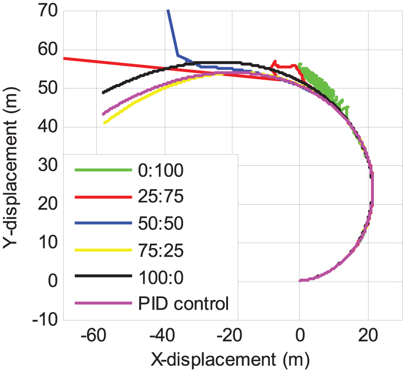
Figures 7 and 8 show the yaw rate responses and vehicle paths on a low

The yaw rate responses with

The vehicle paths with
The above simulation results indicate that with the ratios of 75:25 and 100:0, the vehicle presents superior stability on low
Effects of left–right torque distribution
Similarly, five fixed left–right torque distribution ratios are chosen, which are 0:100, 25:75, 50:50, 75:25 and 100:0. Besides, the following three vehicle manoeuvres are employed in the simulation studies:1,19
Single lane-change manoeuvre on a high
Tuning on a high µ (0.85) road surface with a constant speed of 40 km/h;
Tuning on a low µ (0.2) road surface with an acceleration of 0.5 m/s2.
The steering wheel angle for the first manoeuvre is shown in Figure 9, while the steering wheel angle for the second and third manoeuvres is the same as the one in Figure 2. In the third manoeuvre, the simulated vehicle starts accelerating from rest.

The steering wheel angle for the single lane-change manoeuvre.
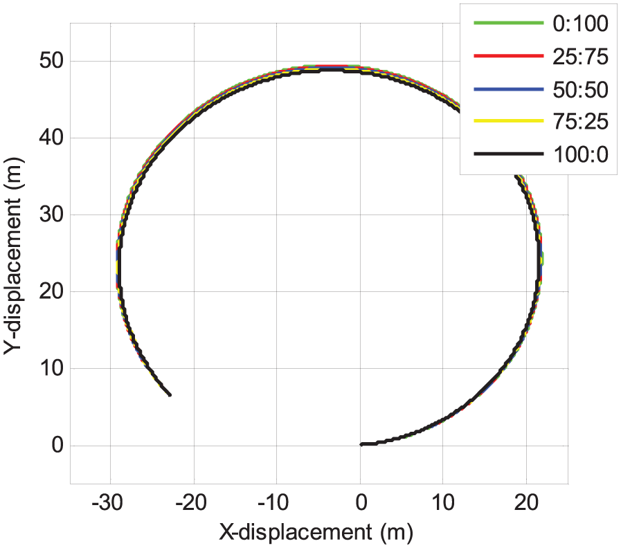
Figures 10 and 11 demonstrate the yaw rate responses and vehicle paths with different torque distribution ratios for the single lane-change manoeuvre. As the driving torque shifts from the right wheels to the left wheels, we see in Figure 10 that the yaw rate decreases as the vehicle turns left, and the yaw rate (absolute value) increases as the vehicle turns right. That is to say, when the direction of torque shift coincides with the turning direction, understeer is intensified (or oversteer is attenuated), otherwise oversteer is intensified (or understeer is attenuated). This is also validated by the vehicle path results in Figure 11.
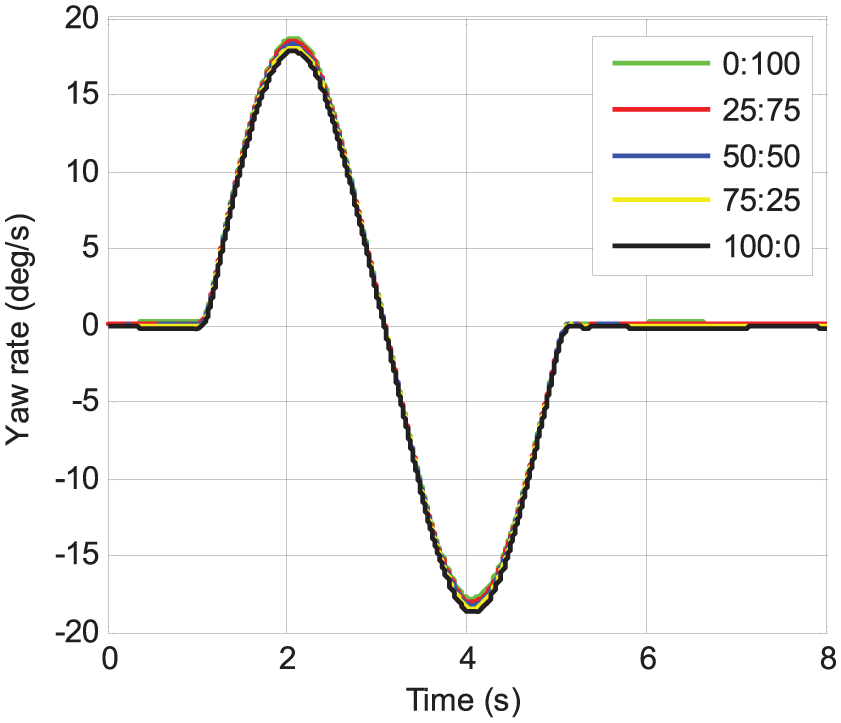
The yaw rate responses for the single lane-change manoeuvre.

The vehicle paths for the single lane-change manoeuvre.
Figures 12 and 13 show the yaw rate responses and vehicle paths with different torque distribution ratios for the second manoeuvre. It is easy to see that as the driving torque shifts to the left, the yaw rate value decreases and the vehicle path bends outwards. Obviously, these simulation results are consistent with the results obtained from the previous manoeuvre.

The yaw rate responses for the turning manoeuvre with constant speed.
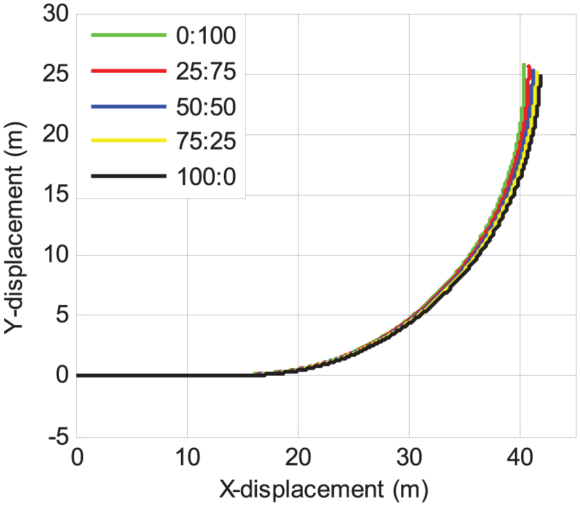
The vehicle paths for the turning manoeuvre with constant speed.
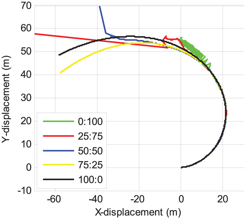
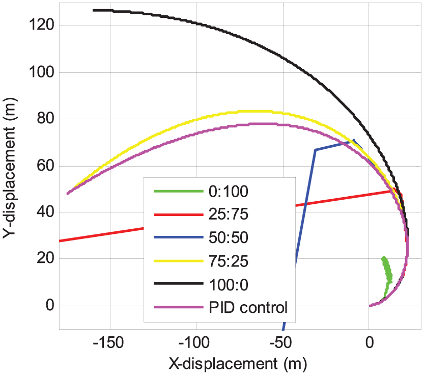
Figures 14 and 15 demonstrate the yaw rate responses and vehicle paths with different ratios for the third manoeuvre. It is shown in Figure 14 that as the driving torque shifts to the left, understeer is intensified, and the yaw rate value decreases. The yaw rate responses with 0:100, 25:75 and 50:50 diverge after t = 11 s, and the corresponding vehicle paths deviate from the stable course. In comparison, the vehicle remains stable with 75:25 and 100:0. Note that the yaw rate values start to drop at about t = 13 s with 75:25 and 100:0, and the explanation on this phenomenon is given in section ‘Turning manoeuvre with acceleration’.

The yaw rate responses for the turning manoeuvre with acceleration.

The vehicle paths for the turning manoeuvre with acceleration.
In short, the simulation results presented in sections ‘Effects of front–rear torque distribution’ and ‘Effects of left–right torque distribution’ provide an important supplement to the two general rules at the beginning of section ‘Effects of torque distribution on stability and handling of four-wheel-drive electric vehicles’ by showing adequate details under several typical driving conditions. These results clearly reveal how the torque distribution between the four driving wheels fundamentally influences stability and handling and give an insight for the controller designs presented in the next section.
Design of torque distribution controllers
Based on the preceding analyses on four-wheel-drive electric vehicles’ stability/handling characteristics, we design in this section two types of controllers to enhance the stability and handling performances of electric vehicles. Specifically, we design a PID controller to adjust the front–rear torque distribution and a sliding mode controller to tune the left–right torque distribution.
Vehicle speed controller
A PID-type vehicle speed controller is designed in this study so as to attain the desired longitudinal speed required by the driver. The error between the desired and actual vehicle speeds,
The control action produced by this speed controller is given by

where
Front–rear torque distribution controller
According to the simulation studies in section ‘Effects of front–rear torque distribution’, the distribution of driving torque between the front and rear axles significantly affects vehicle stability on certain driving scenarios. This fact necessitates the introduction of a controller to actively adjust the front–rear torque distribution in critical conditions. In this section, we design a torque distribution controller to enhance vehicle stability by controlling the vehicle yaw rate.
We define the yaw rate error

where

and

where

where
As mentioned previously, this torque distribution controller is designed to enhance vehicle stability in critical conditions. Namely, this controller does not intervene until the yaw rate error exceeds the threshold. During normal driving conditions, the left–right torque distribution controller (introduced in the next section) is in operation, in order to improve the vehicle handling.
Therefore, the input to this controller,

where
The control action of this controller is to adjust the ratio of the front driving torque to the total driving torque. We might as well define this ratio as

where
Figure 16 shows the schematic diagram of the proposed front–rear torque distribution control system. The controller consists of two controller units – the vehicle velocity controller unit and the torque distribution controller unit. The former unit is employed to generate the torque

Schematic diagram of the proposed front–rear torque distribution control system.
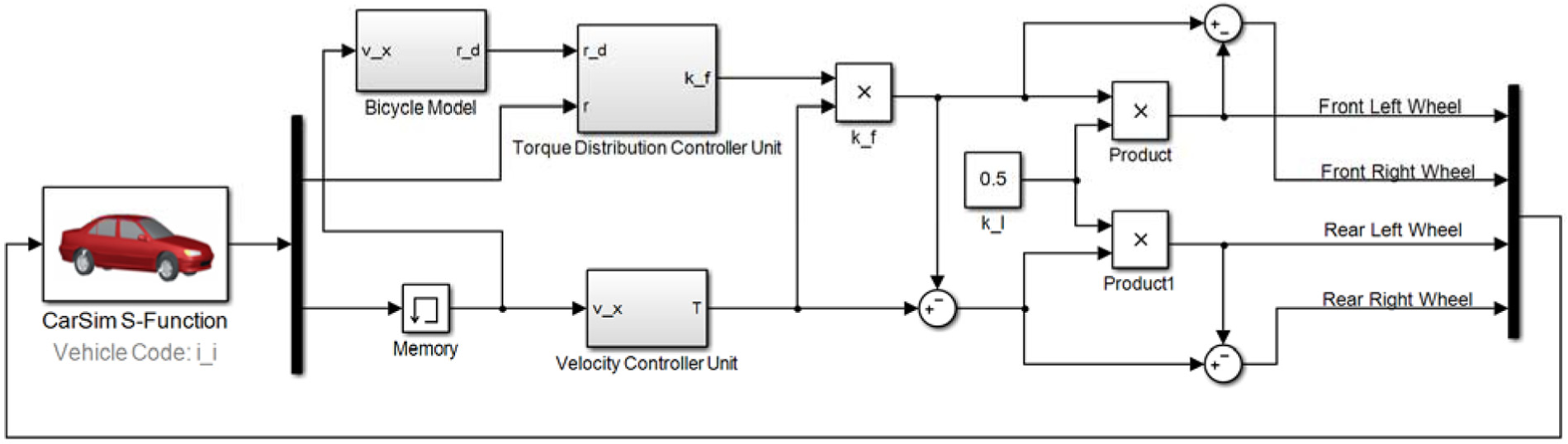
The proposed front–rear torque distribution control system model established for CarSim–Simulink co-simulation.
Because data acquisition is not the focus of this article, we assume that all information fed to the control system is accurate in our simulation studies. In practice, the vehicle velocity can be observed using one of the methods proposed by Imsland et al. 21
Left–right torque distribution controller
Since sliding mode control provides high robustness against uncertainties and disturbances, it has been widely employed in the field of vehicle stability and handling control. In this section, the sliding mode control technique is employed to design a controller to actively adjust the driving torque distribution between the left and right wheels.
In the controller design process, the well-known bicycle model 22 is adopted as the plant to be controlled

where
When a torque distribution controller is on-board, an additional corrective yaw moment

As a result, one derives

We define the switching function of the sliding mode controller in the following form

Apparently

The control objective of the sliding mode controller is to drive the system trajectory to the sliding surface
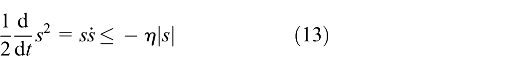
where
To satisfy the sliding condition (13), the following corrective yaw moment is proposed

where
Substitution of equation (14) in equation (12) yields

Therefore, we have

Considering equation (16), when

Then, we have

Similarly, when

Inequalities (18) and (19) imply that to satisfy the sliding condition (13), the control gain
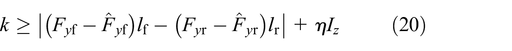
The estimation errors,


where
In practice, the ‘sgn’ function in the control law (14) may cause chattering and jeopardise the control performance. Hence, the ‘sgn’ function is replaced by the ‘sat’ function, and the final corrective yaw moment is written as

where
Finally, the corrective torque command

where
Figure 18 demonstrates the schematic diagram of the proposed left–right torque distribution control system. Similarly, this controller also consists of two controller units – the vehicle velocity controller unit and the torque distribution controller unit. The former unit is the same as the previous one in section ‘Front–rear torque distribution controller’, and the latter unit generates the additional corrective torque
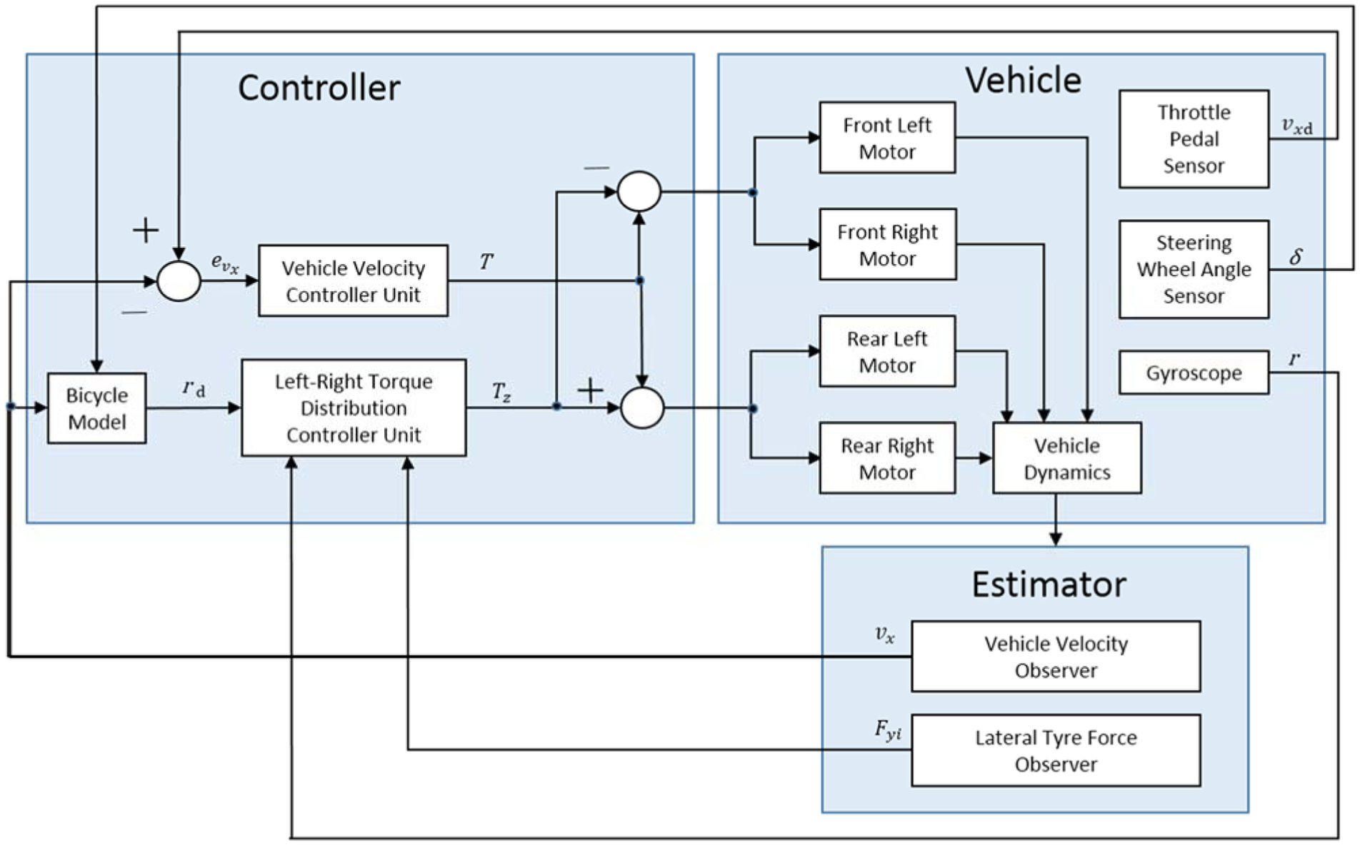
Schematic diagram of the proposed left–right torque distribution control system.
The proposed left–right torque distribution control system model established for CarSim–Simulink co-simulation.
For implementation of the control system, the lateral tyre forces can be estimated by means of the approaches proposed by Doumiati et al. 24 and Baffet et al., 25 and the same methods as in section ‘Front–rear torque distribution controller’ are employed for vehicle velocity observation. Since the estimation techniques are not the focus of this article, accurate signals are fed to the control system in the simulation studies.
Simulation verification
Simulation studies on the front–rear torque distribution controller
As discussed previously, the front–rear torque distribution controller intervenes and enhances vehicle stability in critical conditions. In this case study, the second and third manoeuvres used in section ‘Effects of front–rear torque distribution’ are again employed to simulate dangerously slippery road surfaces and evaluate how the controller performs in such challenging conditions. In the simulation studies, the controlled vehicle response is compared with the responses with different fixed front–rear torque distribution ratios.
Figure 20 shows how the ratio
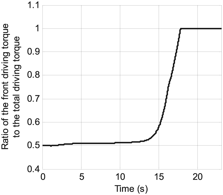
The time history of ratio

The comparison of yaw rate responses with
The comparison of vehicle paths with
Similarly, Figure 23 shows how the ratio
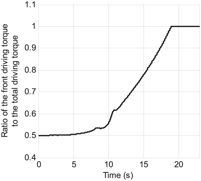
The time history of ratio

The comparison of yaw rate responses with
The comparison of vehicle paths with
Simulation studies on the left–right torque distribution controller
In this section, the same three simulation conditions as in section ‘Effects of left–right torque distribution’ are employed to evaluate the control performance of the left–right torque distribution controller. In the simulation studies, the ideal response is generated from the bicycle model. Besides, the vehicle response without control is compared with the controlled response in the same figure.
Single lane-change manoeuvre
Figures 26 and 27 demonstrate the yaw rate responses and vehicle paths for the single lane-change manoeuvre. On one hand, it is clearly shown that the controlled vehicle tracks very closely the ideal yaw rate response and ideal vehicle path. On the other hand, the uncontrolled vehicle produces remarkable yaw rate error and vehicle path deviation. This yaw rate error results in a lateral deviation of more than 1 m from the ideal course by the end of lane-change manoeuvre.

The comparison of yaw rate responses for the single lane-change manoeuvre.

The comparison of vehicle paths for the single lane-change manoeuvre.
Turning manoeuvre with constant speed
Figures 28 and 29 demonstrate the yaw rate responses and vehicle paths for the turning manoeuvre with constant speed. Similar to the previous manoeuvre, the controlled vehicle closely follows the ideal yaw rate curve; however, the uncontrolled vehicle provides a consistently lower yaw rate response. The effect of the control action suppresses the understeer characteristics, which, in turn, provides a more responsive steering and enhances vehicle handling. This is verified by the vehicle paths shown in Figure 29, where we see that the controlled vehicle completes the turn with a shorter turning radius.

The comparison of yaw rate responses for the turning manoeuvre with constant speed.
The comparison of vehicle paths for the turning manoeuvre with constant speed.
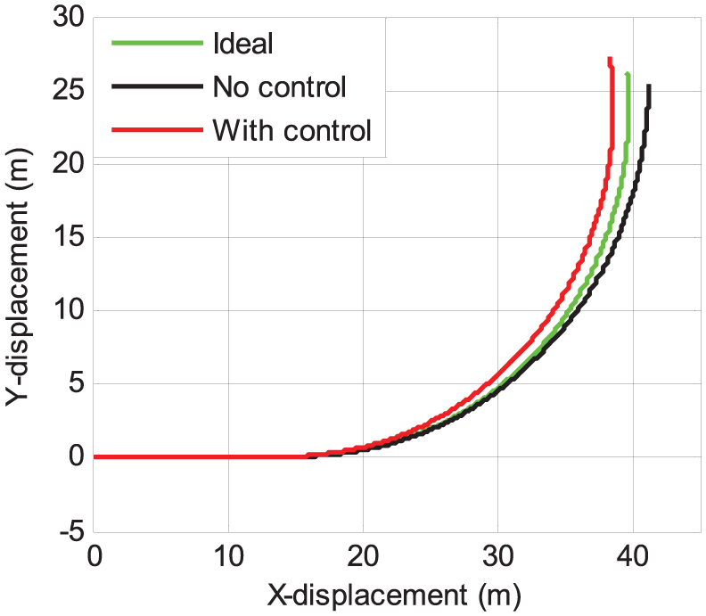
Turning manoeuvre with acceleration
Figures 30 and 31 demonstrate the yaw rate responses and vehicle paths for the turning manoeuvre with acceleration. We see in Figure 30 that the yaw rate of the uncontrolled vehicle diverges and the vehicle loses its stability after t = 13 s. In comparison, the controlled vehicle is able to track the ideal yaw rate response and remain stable. Accordingly, as shown in Figure 31, the path of the uncontrolled vehicle deviates outwards after t = 13 s, while the controlled vehicle successfully completes the turn.
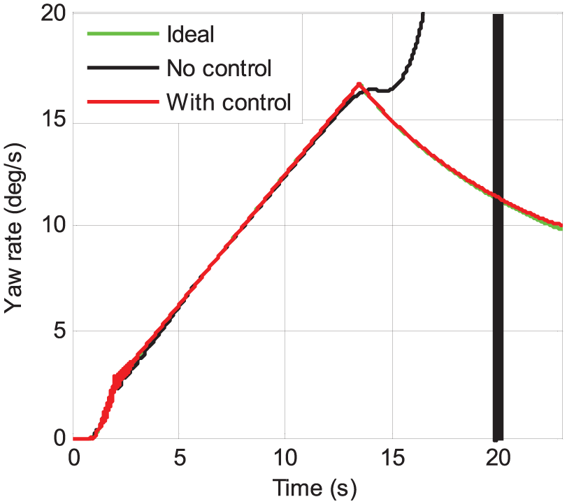
The comparison of yaw rate responses for the turning manoeuvre with acceleration.
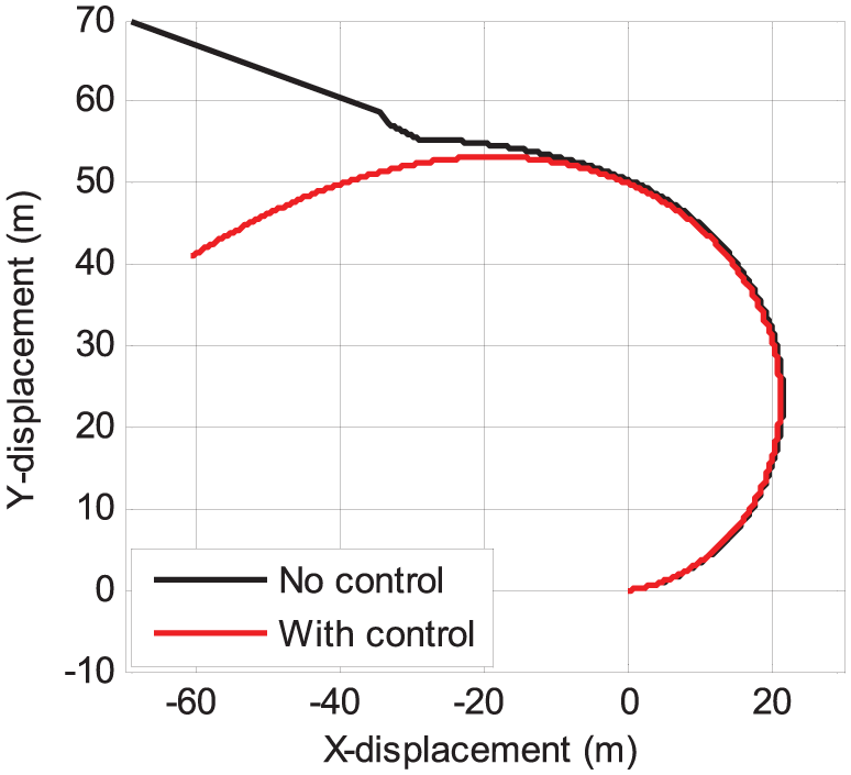
The comparison of vehicle paths for the turning manoeuvre with acceleration.
Note that in Figure 30, the ideal yaw rate (and, in turn, the yaw rate of the controlled vehicle) starts to descend after t = 13 s. This is due to the expression of the ideal yaw rate (see equation (3)), namely, the reference yaw rate (absolute value) decreases as the vehicle speed
The simulation results obtained from the above three manoeuvres indicate that the proposed left–right torque distribution controller is effective in enhancing the handling and stability of electric vehicles in various challenging driving scenarios.
Conclusion and discussion
The independent motor configuration of four-wheel-drive electric vehicles provides advantages for vehicle dynamic control over traditional vehicles. This study establishes a CarSim–Simulink co-simulation model for four-wheel-drive electric vehicles and looks into the stability and handling performances of such vehicles with various torque distribution ratios through CarSim–Simulink co-simulation under several typical driving conditions.
Following the simulation studies, a PID-type controller is devised to tune the front–rear torque distribution, and another sliding mode controller is designed to adjust the left–right torque distribution. The proposed controllers are designed based on the effects of torque distribution on stability and handling of four-wheel-drive electric vehicles. As a result, the operating conditions and control objectives for both controllers are made clear to guarantee better control performance.
The established co-simulation model and the same driving conditions are again employed to evaluate the proposed controllers. The simulation results validate the effectiveness of both controllers in vehicle dynamic control. Particularly, the front–rear torque distribution controller improves the vehicle stability on slippery road surfaces, and the left–right torque distribution controller not only enhances vehicle handling in common driving scenarios but also guarantees vehicle stability in critical conditions.
In our future investigation, a more realistic vehicle model that contains nonlinearities and uncertainties will be taken into consideration for controller design, and more advanced control concepts26–29 which better handle nonlinearities and uncertainties will be employed to further enhance the control performance. Besides, the existing vehicle dynamic control systems for conventional four-wheel-drive vehicles have been experimentally tested and commercialised. In our next study, experimentation will be followed to further verify the effectiveness of the proposed torque distribution controllers, and necessary improvements will be made for implementation on a real four-wheel-drive electric vehicle.
Footnotes
Handling Editor: Hamid Reza Karimi
Declaration of conflicting interests
The author(s) declared no potential conflicts of interest with respect to the research, authorship, and/or publication of this article.
Funding
The author(s) disclosed receipt of the following financial support for the research, authorship, and/or publication of this article: This work was supported by the Fundamental Research Funds for the Central Universities under grant 106112015CDJXY330001 and grant 106112017CDJPT280005.