
Abstract
The objective of this research was an in-depth analysis of energy losses in hydraulic systems. Energy losses were analysed on the basis of the leakage in the annular gap between the spool of hydraulic directional control valves and the hole channel. The impact of various annular gap heights during the different pressure conditions was investigated for two hydraulic fluids with different viscosities: tap water and ISO VG 46 mineral oil. The results were obtained using analytical, simulation and experimental methods. The results of leakage show good agreement between these three approaches. It was shown that grooves with an unusually larger gap (100 µm) led to less leakage in the case of the hydraulic fluid with the lower viscosity. Although the presence of a groove in combination with standard, small gaps (in classic hydraulic systems: 1 µm–5 µm) leads to greater leakage, the grooves are important to reduce the contact pressure along the sealing side of the spool, friction and wear.
Introduction
Hydraulic systems require the use of different types of fluids. Mineral oil is very often used, while tap water is becoming increasingly important because of sustainable development 1 and the latest research findings in science. 2 The use of fluids and the non-ideal geometry of hydraulic components lead to leakage, which represents losses in hydraulic systems. 3 It is very difficult to ensure zero leakage, but it can be minimized with seals. There are moving parts inside hydraulic components (e.g. valves, pumps and motors) that are normally sealed with small annular gaps, without any additional elastic seals. 4 It is generally known that annular grooves reduce the friction and wear between the spool and the hole, but little is known about their influence on the internal leakage through the gap. Moreover, an ecological approach is very important and the use of water as a hydraulic fluid can protect the environment. However, tap water as a hydraulic pressure medium still poses a lot of unanswered questions. 5 This article will attempt to answer some of these questions.
An accurate prediction of the leakage flow rate through a seal is a very difficult challenge due to the great variety of parameters, such as the geometry, pressure differences, temperature and type of fluid. 6 The leakage flow rate affects the system’s stability as well as its response. 7 Even though there are many factors that are related to the leakage flow, 8 there is a tendency to use simple models to estimate the fluid flow. 9 Pressure is one of the most significant factors that influence the leakage in hydraulic systems. 10 There are many types of hydraulic spool valves, which lead to different pressure distributions and affect the volume flow rate, the lateral force and the friction force in various different ways. 11 It has been shown that the shape of the groove strongly influences the flow characteristic of the spool valve and some other factors, such as the flow area, the discharge characteristics, the jet-flow angle, the throttling stiffness and the steady flow force. 12 There are many papers that describe how the geometry of the labyrinth passage influences the pressure and velocity contours. 13 The volume flow rate and leakage are very much related to the flow conditions, with respect to laminar and turbulent flow, 14 which are identified through the Reynolds number. Some leakage is present in almost every hydraulic machine. There are many places where leakage can occur. 15 Kumar and Bergada 16 analysed the influence of grooves, the location of grooves and the number of grooves on the leakage for three different piston diameters in axial piston pumps. It was shown that the grooves have a significant influence on the pressure distribution and the forces. In the same paper, the relations between the leakage and the eccentric position (from 0 to 10 µm), the different groove configurations (five configurations) and the different clearances were investigated. It was proved that the leakage increases in the case of larger clearances. 8 The results refer to two different sizes of clearances (15 and 20 µm). Clearances have an enormous effect on the flow losses and the efficiency of hydraulic systems.17,18 In recent decades, water hydraulics has received greater recognition. There are many challenges in terms of labyrinth seals, due to the very thin lubrication film, 19 when compared with oil hydraulics. Asok et al. 20 investigated the pressure-drop characteristics for the leakage of water through circular, grooved, square- and curved-cavity, static labyrinth seals. Five different square-cavity labyrinth seals were subjected to flow-visualization tests to observe the leakage flow patterns. The leakage flow through labyrinth seals depends on the groove’s dimension. More precisely, the labyrinth height-to-width ratio for the laminar incompressible flow and the number of seals with various shapes were analysed. 3 According to some assumptions, the leakage decreases in the case of unequal clearance sizes at the entrance and exit of the seal. Min et al. 21 simulated the flow field in the fit clearance for a large spool valve. They found the relationships between the leakage and the number of grooves, on one hand, and the leakage and the eccentricity on the other. An analysis of the leakage at different inlet pressures was carried out. The authors proposed some reasons as to why the experimental leakage is usually greater than the simulation values. Due to the higher working pressure, this increases the temperature and decreases the viscosity, and there is an influence of the eccentricity as well. The internal leakage flow significantly affects the valve’s behavior,22,23 while pressure gain and the internal leakage characteristics were introduced. The external leakage was found to be greater than the theoretically predicted value for the leakage. Similar findings were discussed by Min et al. 21
If we focus on the leakage in the spool valve, there are very simple, linear relationships between the leakage and the pressure, but on the other hand, there is a relationship between the leakage and the clearances that follows a cubic function. 19 Similar findings were described in the case of an axial piston pump grooved slipper analysis. 24 Pressure, leakage, force and torque variations were analysed, and different groove dimensions were used. It was shown that the leakage increases if the width of the groove increases. Furthermore, the leakage increases with an increase of the groove depth, although when the depth exceeds a certain value, the leakage was nearly constant and independent of the increase in the groove depth. Two different widths (1 and 2 mm) and three different clearances (6.5, 10 and 20 µm) were analysed. The leakage in spool valves causes flow forces that are most of the time undesirable. It was proven that leakage gain leads to to an increase in the flow force. 22 Another negative consequence is vibration. 25 There are different labyrinth seals in hydraulics. Wang and Lie 26 proved that a stepped seal showed better sealing performance than an interlocking seal. They investigated velocity vector maps of the fluid in the above-mentioned seals, the distribution of the turbulent kinetic energy and the distribution of the pressure along the seals. Many researchers confirmed that the geometrical configuration of the grooves plays a major role in the pressure drop, which then affects the leakage. Some advanced configurations were investigated. 4 Circular, sinusoidal and helical grooved, square-cavity labyrinths were tested. There are also some other aspects that concern friction and wear. 13 In an experimental study of the wear interaction between a piston ring and a piston groove in a radial piston hydraulic motor, it was shown that the form of the groove significantly influences the amount of wear. 27
The main purpose of this article is to investigate the influence of the groove on the leakage for two different gap heights (6.5 and 100 µm) and two different fluids (water, oil), with three kinds of approaches (analytical, simulation, experimental). The remainder of this article is structured as follows. Section ‘Theoretical background’ describes the theoretical background. The methodology is explained in section ‘Methodology’. The results are presented in section ‘Results’. The research findings are discussed in section ‘Discussion’, while section ‘Conclusion’ consists of the conclusion and ideas for further research.
Theoretical background
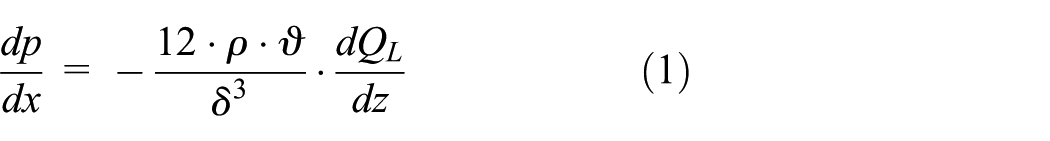
The annular gap is the basic element of hydrostatics. Many parts of hydraulic components (e.g. the piston and the piston rod in hydraulic cylinders) do not have classic elastic sealing between the relative moving parts. The sealing quality in hydrostatic annular gaps depends largely on the gap height. A uniform effective pressure gradient in the x-direction, between two parallel plates, is expressed with equation (1) 28
where

The annular gap height between the spool and the hole can be determined using equation (3)

where

Centric position of the spool in the hole.
The volume flow rate through a smooth annular gap without grooves can be calculated using equation (4), where a Hagen–Poiseuille laminar flow is considered.23,26 This volume flow rate through the gap is normally referred to as the leakage flow (QL)

where Δp is the pressure difference, Dsr is the middle diameter in the gap, s is the height of the annular gap where the spool is centred in the hole, ρ is the fluid density,
Annular grooves or labyrinth seals are channels added to the smooth annular gap. According to the literature,29,30 grooves have triple function. The first function of these annular grooves is the normalization of the pressure in each groove, where the step pressure drop and the centric position of the spool are the consequences. The second function is reducing the radial force on the spool to whole surface. Figure 2 shows the reduction of the contact force depending on the number of annular grooves. It was taken into account that the width of the grooves is always greater than the height. This function is mostly used by the sliding type of directional control valve, where a rapid response without stopping the spool is required.

Reduction of the contact force depending on the number of grooves. 31
The third function of the groove 30 is a reduction of the leakage from the gap. It is generally believed that the turbulence flow in an annular groove (Figure 3) can cause a pressure drop from the inlet to the outlet of the groove. In this way, the annular grooves simply represent a labyrinth sealing.29,30

Turbulence of the fluid flow in the annular groove. 32
The pressure drop due to the volume flow rate through the annular passages of the labyrinth seal can be calculated with equation (5) 19

where

The Reynolds number is calculated using equation (7)

where

Pressure drop of the fluid flow through three annular grooves. 30
Methodology
This article deals with the influence of two different fluids (water and oil), two different gap heights (6.5 and 100 µm) on the leakage observed with three different methods (analytical, simulation, and experimental). Two different spool types were analysed (with grooves and without grooves). A graphical presentation of the applied parameters and the methods of the conducted research are presented in Figure 5. Every parameter or method has its own notation. For example, W means water, G is a spool with a groove, S is a simulation and 6.5 means a gap height with a size of 6.5 µm. The combination of letters W-G-S-100 means that water is used as the fluid, the spool has grooves, the simulation approach is applied and a gap height of 100 µm is analysed.

Methodology of the conducted research.
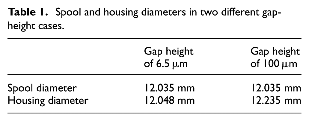
Two different gap heights were investigated (Table 1). The first one is 6.5 µm, and the second one is 100 µm. In both cases, the spool diameter was 12.048 mm. The housing diameters were different. In the first case, it was 12.035 mm and in the second case, it was 12.235 mm.
Spool and housing diameters in two different gap-height cases.
Simulation approach
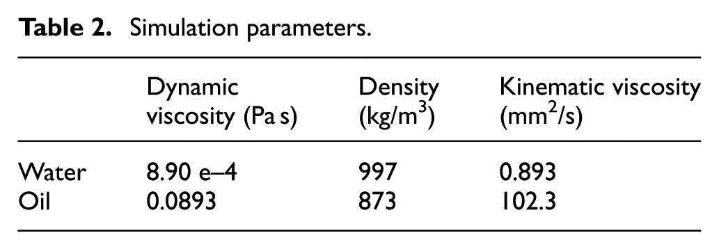
For the simulation research activities, we used two fluids with different physical properties. A fluid temperature of 25°C was considered. The water had a dynamic viscosity of 8.90 e–4 Pa s and a density of 997 kg/m3. If we took into account the equation for kinematic viscosity ν = µ/ρ, we obtained a kinematic viscosity of 0.893 mm2/s. ISO VG 46 oil was used. Its dynamic viscosity was 0.0893 Pa s, its density was 873 kg/m3 and the kinematic viscosity was 102.3 mm2/s (Table 2).
Simulation parameters.
Two types of spools were analysed. The first type did not have any grooves, whereas the second type had five square annular grooves. Regarding the mesh generation, the first type had 4.4 e6 elements in the grid and the second type had 5.1 e6 elements, as shown in Table 3. Detailed simulation grids for both types are presented in Figures 6 and 7.
Number of elements in the grid.


Grid, no groove, a gap height of 6.5 µm.

Grid, groove, a gap height of 6.5 µm.
We applied a commercial CFD software ANSYS CFX. An all quad free face mesh type was chosen. A mesh was generated by the ‘Sweep’ method. Element size was 0.03 mm, whereas the desired number of axial divisions was 20. We used an element-based finite volume method, which involves discretizing the spatial domain using a mesh. The mesh was used to construct finite volumes, which are used to conserve mass, momentum and energy. The set of governing equations solved by ANSYS CFX were the unsteady Navier–Stokes equations in their conservation form. We have taken into account that (1) the mass of a fluid is conserved, (2) the rate of change of momentum equals the sum of the forces on a fluid particle (Newton’s second law) and (3) the rate of change of energy is equal to the sum of the rate of heat addition to and the rate of work done on a fluid particle (the first law of thermodynamics).
The gap investigated in this article is at order of micrometer. According to Hessel et al., 33 the usual macroscopic descriptions can be applied. Genuine micro scale effects mainly appear in gas-phase systems, whereas for many practical applications liquids in micro channels can be described by the usual continuum models.
The grid independence tests were completed. The water and oil leakage flow have been analysed for different sizes of mesh. According to the selected mesh size and the simulation result, we concluded that the flow leakage was independent of the number of elements in a grid. An example of a grid-independence test is shown in Figure 8, where the water leakage with and without grooves for a gap height of 100 µm was presented.

A grid independence test.
Experimental approach
Two different hydraulic fluids demand two different hydraulic test rigs. Figure 9 shows the water hydraulic scheme. The high-pressure water pump (pos. 2) sucks tap water from the reservoir (pos. 1) and pushes it through the high-pressure water filter (pos. 6) using the hydraulic accumulator (pos. 7) through the open ball valve (pos. 8) to the specimen (pos. 9). The leakage flow through the specimen was measured with the help of the test tube (pos. 10). The structure of the oil hydraulic test rig was very similar to the presented water hydraulic test rig. The power pack and tested valve of the water hydraulic test rig are presented in Figure 10.

Water hydraulic scheme.

Experimental setup of the water hydraulic test rig.
Figure 11 shows the 10 different tested (customized) spools that were produced in the company Poclain Hydraulics Slovenia. These spools are part of a standard oil hydraulics directional control valve. On the left-hand side of Figure 11 are five spools with grooves, and on the right-hand side, we can see five spools without grooves. The spools were fixed in position in the hole of the directional control valve. The leakage flow was measured at different pressures, whereas the fluid temperature was constant at 25°C.

Ten different tested (customized) spools.
The diameter, the deviation from cylindricity and the roughness Rz were determined for every tested spool. The spool diameter was 12.035 mm. The average deviation from cylindricity was 1.43, whereas the average roughness Rz was 0.74 µm. The data are shown in Appendix 2 (Table 5).
Results
The results in this section are presented descriptively and graphically. However, due to a reduction in the amount of information, some shortening of the applied parameters and methods was applied (Table 4).
Result presentation-series signs in figures.

Analytical approach
Figure 12 shows the results for an analytical calculation (using equation (4)) of the leakage flow through smooth surfaces without grooves in the case of water, whereas the results for oil are shown in Figure 13. The maximum water-leakage rate was 0.23 L/min, while for oil leakage it was 0.0023 L/min, for the case of a gap height of 6.5 µm and a pressure of 200 bar. The tested oil had an approximately 100-times-larger viscosity than the water. This led to a 100-times-lower oil-leakage rate.
Leakage of water, no grooves, analytical approach, 6.5 µm gap height.

Leakage of oil, no grooves, analytical approach, 6.5 µm gap height.
Simulation approach
Figure 14 shows the results of the simulation approach for the case of water, whereas the results for oil are shown in Figure 15. A gap height of 6.5 µm without grooves was taken into consideration. The maximum water-leakage rate was 0.30 L/min, while the oil-leakage rate was 0.0042 L/min for the case of a pressure of 200 bar. Due to the much lower viscosity of water in comparison to oil, the leakage rate of the water was much greater.

Leakage of water, no grooves, simulation, 6.5 µm gap height.

Leakage of oil, no grooves, simulation, 6.5 µm gap height.
Influence of grooves during the simulation approach
The result of additional simulations shows the influence of grooves on the water and oil leakage flow for the case of a gap height of 6.5 µm. The water leakage flow with grooves was on average 47% greater than the leakage without grooves (Figure 16). According to the simulation results, the grooves also increase the leakage with oil (Figure 17). The oil leakage with grooves was, on average, 110% greater than the leakage without grooves.

Leakage of water, simulation, 6.5 µm gap height.

Leakage of oil, simulation, 6.5 µm gap height.
Figure 18 shows the numerically calculated pressure distribution along the 6.5-µm gap in the oil domain. The pressure difference between the inlet and the outlet was 50 bar. The pressure distribution was much more homogeneous without the grooves. Pressure is smoothly falling from the left to the right side along the gap (Figure 18(a)). In the case of grooves, pressure falls sharply where the groove appears (Figure 18(b)). It is clear in terms of the different colours and the clear boundaries between them. A similar result was achieved with a simulation of the water-pressure distribution.

The profile of pressure distribution (6.5 µm gap, the oil domain): (a) no grooves and (b) grooves.
Figures 19 and 20 show the flow-velocity profile through a 6.5 µm gap height with a 0.5-mm squared groove for a pressure drop of 50 bar. The maximum velocity of the water was 12 m/s (Figure 19), while the maximum velocity of the oil was 0.32 m/s (Figure 20). A greater degree of swirling was observed in the water groove, whereas the velocity profile for the oil groove did not show such a flow intensity.

Velocity conditions in the water domain.

Velocity conditions in the oil domain.
Experimental approach
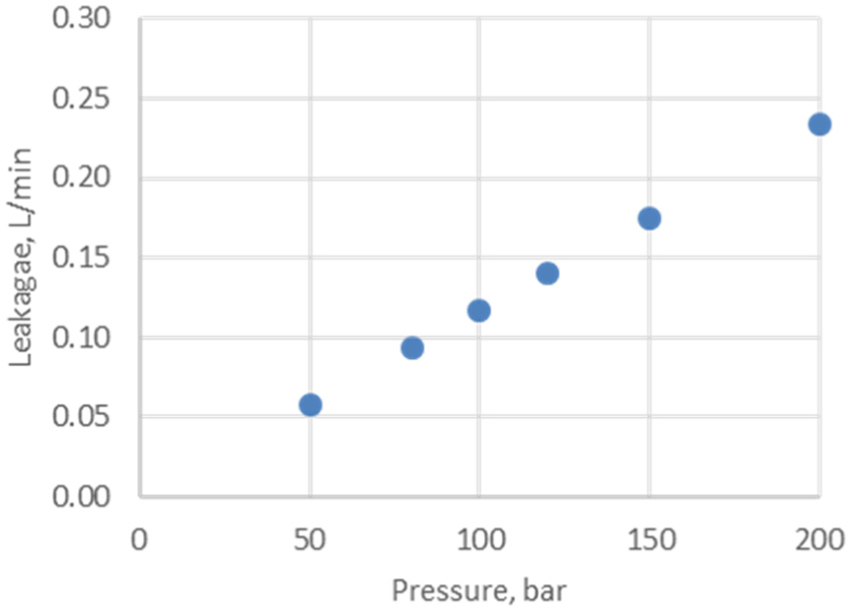
The influence of grooves on the leakage was analysed using an experimental approach for two different hydraulic fluids (water and oil). The applied gap height was 6.5 µm. The maximum leakage flow in the case of water was 0.24 L/min at a pressure of 120 bar (Figure 21) and 0.02 L/min for oil at a pressure of 200 bar. The most important result of the experimental research was the increased leakage flow when the grooves were introduced. The leakage flow of water was 110% greater in the case of grooves, compared to the situation without grooves, whereas the leakage flow of oil was 159% greater (Figure 22).

Leakage of water, experimental approach, 6.5 µm gap height.

Leakage of oil, experimental approach, 6.5 µm gap height.
Discussion
The research consists of three different approaches: analytical, simulation and experimental. The results of the water investigation show good agreements between all the applied methods (Figure 23). The highest values of the leakage were obtained within the simulation approach. The difference between the analytical and simulation approaches was acceptably low. The experimental results were close to the results of the analytical approach. On the other hand, the experimental results for the oil leakage show slightly higher values than the results for the simulation and analytical approaches (Figure 24).

Leakage of water, no grooves, 6.5 µm gap height.

Leakage of oil, no grooves, 6.5 µm gap height.
The main reason for above-described experimental deviation is the non-ideal spool geometry, which is a consequence of a non-ideal manufacturing process. Figure 25 presents the results of an accurate geometrical measurement of the tested spool. The average cylindricity error was 2.74 µm, which affects the accuracy of the measurement. As we can see in equation (4), s is the height of the annular gap and there is cubic correlation between the height of the annular gap (s) and the leakage flow (QL). The second reason for the slightly higher values of the experimental results is the lower local viscosity due to the increased local temperature. A working fluid with a dynamics viscosity of around 100 cSt and more generates heat and easily increases the local temperature of the working fluid during the laboratory experiments of fluid flow between a very narrow gap. During the experiments, we tried to keep the temperature of the working fluid the same as we took into account in the simulation and analytical approach. We observed that the average temperature of the working fluid was 1.1°C higher than expected. The third possible reason is small air bubbles which can be generated in such high viscosity fluid during the laboratory experiments. Air bubbles destroy a laminar boundary layer. 34 Consequently, the shear forces are lower and leakage flow is higher.
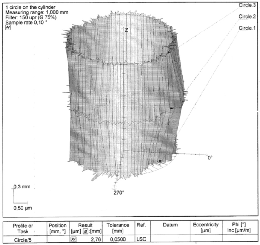
Presentation of the cylindricity error for a randomly selected tested spool.
The numerically calculated leakage of water through the 6.5-µm height gap with grooves was very similar to the experimental approach (Figure 26). The results differ, on average, by 4%. In the case of oil, the experimental leakage had higher values than the leakage obtained with the simulation approach. A possible reason for such a difference is the uncontrolled radial position of the spool in the hole during the experimental research. An up to 2.5-times-greater oil leakage was observed, which is completely consistent with the theoretical background (Figure 27).20,35

Leakage of water, grooves, 6.5 µm gap height.

Leakage of oil, grooves, 6.5 µm gap height.
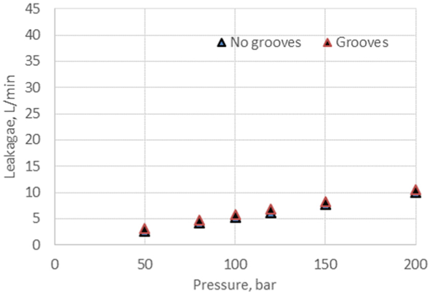
One of the most important contributions of this article is that annular grooves as part of labyrinth sealing only decrease the leakage in the case of larger gaps and a lower viscosity. This was proven through the additional simulation of a 100-µm gap (Figure 28). The presence of grooves with a larger gap led to a lower water-leakage rate in comparison with the same gap height without the grooves. The opposite is true in the case of smaller gaps, whereas the grooves increase the leakage independently of the fluid’s viscosity (Figures 16 and 17). It was assumed that the 100-µm oil gap, in connection with the higher viscosity, was too low to ensure the functioning of the labyrinth sealing (Figure 29).

Leakage of water, simulation, 100 µm gap height.
Leakage of oil, simulation, 100 µm gap height.
In this case for the numerical simulations, no flow swirling was observed. The consequence was a leakage flow through the gaps with the annular grooves that was greater than in the case of the smooth gap without annular grooves. The presented work shows that the annular grooves in the sliding contact with a small gap increase the leakage, although one of the main functions of the annular grooves in hydraulic applications is the pressure relief along the sealing side of the spool and, consequently, centring the spool in the hole to decrease its sliding friction, wear and leakage at the same time.
Further research will involve analysing the leakage through larger gaps up to 200 µm. The results of the simulation will be compared with the experimental results. The leakage for different levels of eccentricity of the spool position in the hole should be investigated carefully. Another hot topic for further research is the relationship between the number of grooves and the leakage. We would like to investigate whether more grooves lead to greater leakage. Additionally, the influence of different groove shapes (square, triangular, semi-circular) on the leakage should be investigated.
Conclusion
The leakage flow through an annular gap in water and oil hydraulics was investigated. The influence of a groove on the leakage was demonstrated with three different methods. Analytical, simulation and experimental approaches were applied and compared. A generally accepted mathematical model for the leakage through a smooth, annular gap was considered in the analytical approach. A CFD analysis was carried out to calculate the leakage flow for the different parameters. The same parameters were used in the frame of the water and oil experimental research. The results of all three analyses led to the following conclusions:
The results for the defined leakage of water were in good agreement for all the applied methods (analytical, simulation and experimental). Some disturbances of the oil leakage were found within the experimental approach due to the geometrical irregularities and higher viscosity. An uncontrolled radial position for the spool has a very important influence on the leakage. The maximum eccentric position of the spool can lead to a 2.5-times-greater leakage.
There is one additional fact that helps us to explain why the experimental results were a little different to the results of the analytical and simulation approaches. During the experimental testing, it is very difficult to measure the local temperatures that influence the local viscosity. This is a very important factor because it is linearly related to the leakage. A lower viscosity leads to greater leakage.
The gap height has a very important influence on the leakage flow in connection with the presence of a groove. The volume flow rate through a small gap is much smaller than the volume flow rate through a larger gap. There is a cubic relation between the gap height and the leakage. Furthermore, a low volume flow rate leads to a lower fluid-streamlines velocity, which means the grooves do not have a sealing function. On the other hand, a larger gap affects the higher fluid-streamlines velocity and, consequently, the grooves gain an appropriate sealing function.
In the case of grooves being present, and with the same gap height and the same pressure difference, viscosity plays a very important role in the functionality of labyrinth sealing. If we put the focus on the 100 µm gap height, the groove decreased the water-leakage rate, but increased the oil-leakage rate.
The gap heights in hydraulics are usually between 1 and 5 µm. It was proven that within this range, the presence of grooves leads to greater leakage in water and oil systems. Although the presence of a groove has some positive consequences, such a pressure relief along the sealing side of the spool and centring the spool in the hole to decrease its sliding friction and wear, the leakage was greater due to the lower friction at the solid/fluid interface.
Footnotes
Appendix 1
Appendix 2
Characteristics of the tested customized spools.

| Spool # | Di (mm) | Deviation from cylindricity (μm) | Rz (μm) | |
|---|---|---|---|---|
| Spools with annular grooves | 1 | 12.035 | 1.33 | 0.63 |
| 2 | 12.035 | 0.84 | 0.524 | |
| 3 | 12.035 | 1.27 | 0.608 | |
| 4 | 12.035 | 1.09 | 1.536 | |
| 5 | 12.035 | 1.25 | 0.802 | |
| Spools without annular grooves | 6 | 12.035 | 1.26 | 0.671 |
| 7 | 12.035 | 0.94 | 0.733 | |
| 8 | 12.035 | 2.36 | 0.627 | |
| 9 | 12.035 | 2.56 | 0.63 | |
| 10 | 12.035 | 1.39 | 0.668 |
Handling Editor: Junwu Wang
Declaration of conflicting interests
The author(s) declared no potential conflicts of interest with respect to the research, authorship, and/or publication of this article.
Funding
The author(s) disclosed receipt of the following financial support for the research, authorship, and/or publication of this article: This work was supported by the company Poclain Hydraulics Slovenia.