
Abstract
Research on tool path planning has been limited to minimize airtime by optimizing tool travel path in one machining plane without obstacles. To address this limitation, a method for tool path optimization that exploits A* and genetic algorithms to find the near-optimal safe cutting tool travel path between each drilling hole location by avoiding the nonmachinable areas is proposed. A series of experiments performed shows an average overall improvement of 38.8% over the cutting tool travel distance value obtained from traditional tool path method.
Keywords
Introduction
The cost of machining has always been a primary interest to researchers. 1 In manufacturing processes, the most commonly used optimization criteria are specific cost of machining which has been used by researchers since the beginning of this branch. 2 Optimization of cutting parameters like feed rate and depth of cut is usually a difficult work where the following aspects are required: knowledge of machining, empirical equations relating to tool life, forces, power, surface finish, and so on. 3 Sometimes, other criteria like machining time, material removal rate, and tool life have also been used in optimization procedure to reduce the machining cost. 4 However, less attention has been paid to reduce the nonproductive airtime, though it too can be quite significant. 5 Hence, the other aspects of the machining processes are the cycle time and airtime of the tool, where intelligent programming could be applied to save time and to reduce the cost of machining, thereby increasing productivity.
The difference could be noticed when there are multiple tools being used to machine small regions at different locations. Generally, tool path planning was done by the computer-aided design (CAD) or computer-aided manufacturing (CAM) programmer or by the machine operator. It has always been a challenge to improve the reliability of computer numerical control (CNC) machines. 6 It is up to the skill of the programmer or machine tool operator to detect accidents and to reduce the cycle time by changing the tool travel path. Currently, a number of CAD/CAM packages that provide automatic numerical control programming have been developed and applied to various processes of machining.
Optimization techniques and methods have been introduced in all the fields of engineering activities and also in CAD/CAM systems. 7 There are quite a number of literatures related to tool path optimization that could be found, and most of them used genetic algorithm (GA), artificial neural network, ant colony optimization, artificial immune systems, Lin–Kernighan algorithm, and particle swarm optimization. 8 There were studies that focused on finding the shortest cutting tool travel path for hole-cutting operation with GA and formulated cutting tool travel path as a special case of traveling salesman problem. 9 Ant colony optimization algorithm was used in minimizing the summation of tool switching time and tool airtime in hole-making operation. 10 It was also used to find the optimum travel path by finding the best sequence for hole-cutting operation. 11 Modified machine ant colony optimization was used in cutting optimization for multi-pass turning operation. 12 Lin–Kernighan algorithm was used in optimizing cutting and welding paths by modifying the coordinate data and finding the near-optimal tour. 13 There was an attempt to use GA for different processing techniques in tool path optimization in order to minimize the unproductive airtime during machining. 14 GA was also used to determine the best sequence of operations for a set of operations that are located in asymmetrical locations and different levels. 15
However, all the above previous works are limited to minimize airtime by optimizing tool travel path in one machining plane without any obstacles or nonmachinable areas. As in the case of drilling holes on a printed circuit board or drilling multiple holes located in the form of a matrix on a sheet of metal. To address this limitation, in this article, we deal with optimizing tool path in one machining plane with obstacles, which is the first attempt to the best of our knowledge in CNC domain. Therefore, we propose a tool path optimization method that exploits A* algorithm and GA to find the near-optimal safe cutting tool travel path between each drilling hole location by avoiding the nonmachinable areas. The proposed method can be applied in commercial CAD/CAM packages to minimize the cutting tool airtime and increase the capability of machine with short tool retraction height for automatic generation of CNC programs.
Proposed A* algorithm and GA for shortest tool path
The CAD models of the component selected for testing are sample work piece of 500 × 500 × 100-mm solid steel with profiles as shown in Figure 1. The components that are used for testing is at the intermediate process of manufacturing and being completed into a mold. A number of holes with higher depth are required to be drilled on the component.

CAD model of the selected components: (a) CAD sample 1, (b) CAD sample 2, (c) CAD sample 3, and (d) CAD sample 4.
Image processing is first processed with the top view of CAD model which converts the acquired color image into gray-scale image using the hue and saturation elimination on the image, followed by noise removal using two-dimensional (2D) median filtering technique. Using Otsu’s 16 method, a global threshold is calculated and then the gray-scale image is converted into a binary image. This image is then further processed using image processing techniques for boundary tracing. 17 The methodology of the image processing algorithm is also explained in Figure 2. The acquired traced boundary is then morphologically thinned using boundary cleaning algorithms. Therefore, the final converted image is shown in Figure 3 and is in the form of black and white image with black representing all the projected parts and edges and white representing the machinable areas.

Methodology for converting image to boundary edges using image processing techniques.
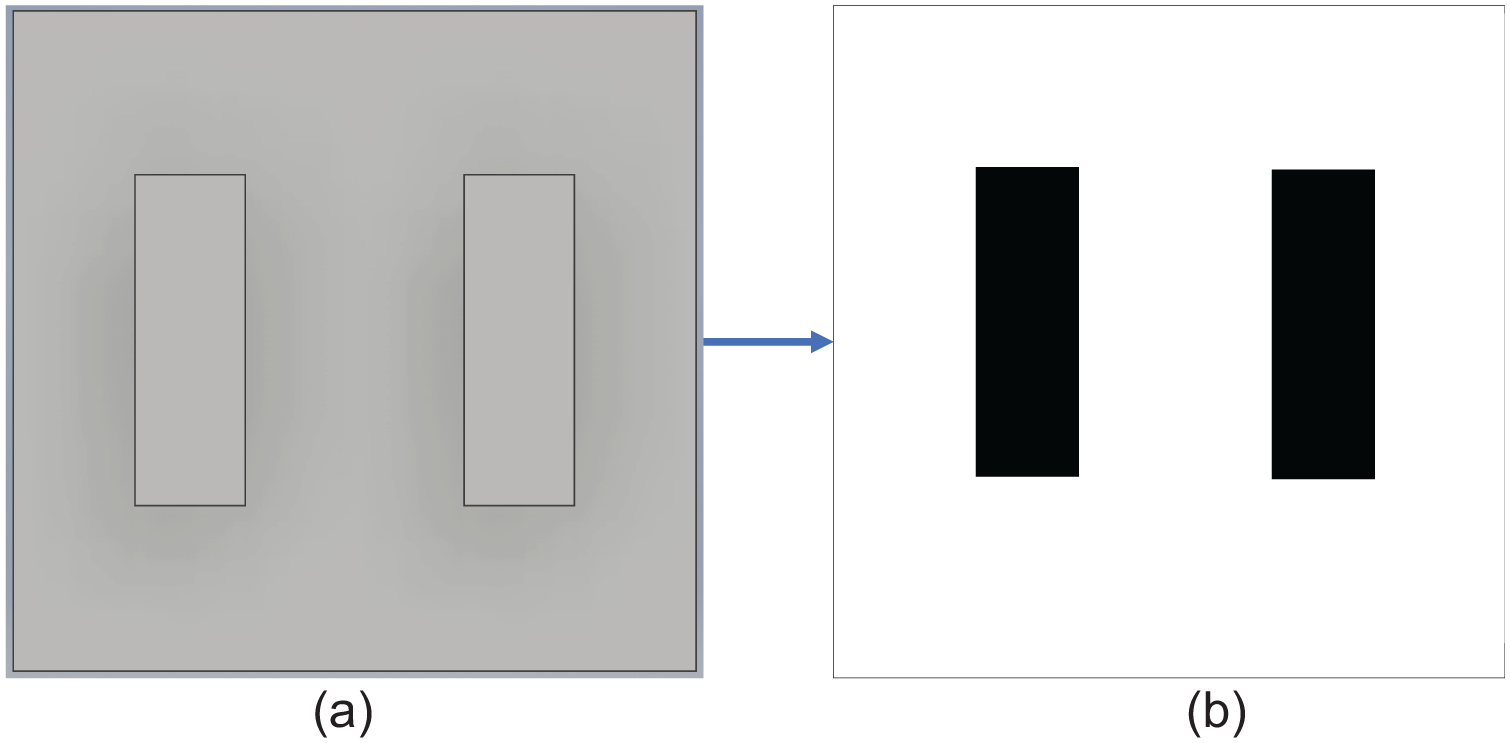
Image conversion of top view of the component: (a) original CAD image and (b) converted image.
The locations where hole must be drilled are known, and all possible pairs of hole combinations are considered. The image is then used as an input for finding the optimal safe cutting tool travel path between each pair using evaluation function to sort the nodes. It finds the best possible path between two hole locations by considering conditions like the least traveled distance and least time for traveling. Therefore, we use A* algorithm that follows best first search method to find the optimum safe cutting tool travel path between two sets of hole locations. The A* algorithm mainly uses an evaluation function as shown below

Here, in equation (1), n is the last node on the path,
In this article, we have considered the input image as a graph consisting of vertices and edges. Each pixel is then taken as a vertex indicated in blue boxes as shown in Figure 4(a). Every single vertex has several collision-free links that act as edges. In this algorithm, the position of the tool is given a weightage of 2. Since a CNC tool can move in all the directions like rectilinear and diagonal, the neighboring pixel matrix is given a weightage of 1 as shown in Figure 4(a). If the tool cannot move along any direction, then a weightage of 0 is assigned to the matrix. This weight matrix could be changed according to the capability of the machine and its allowed movement.
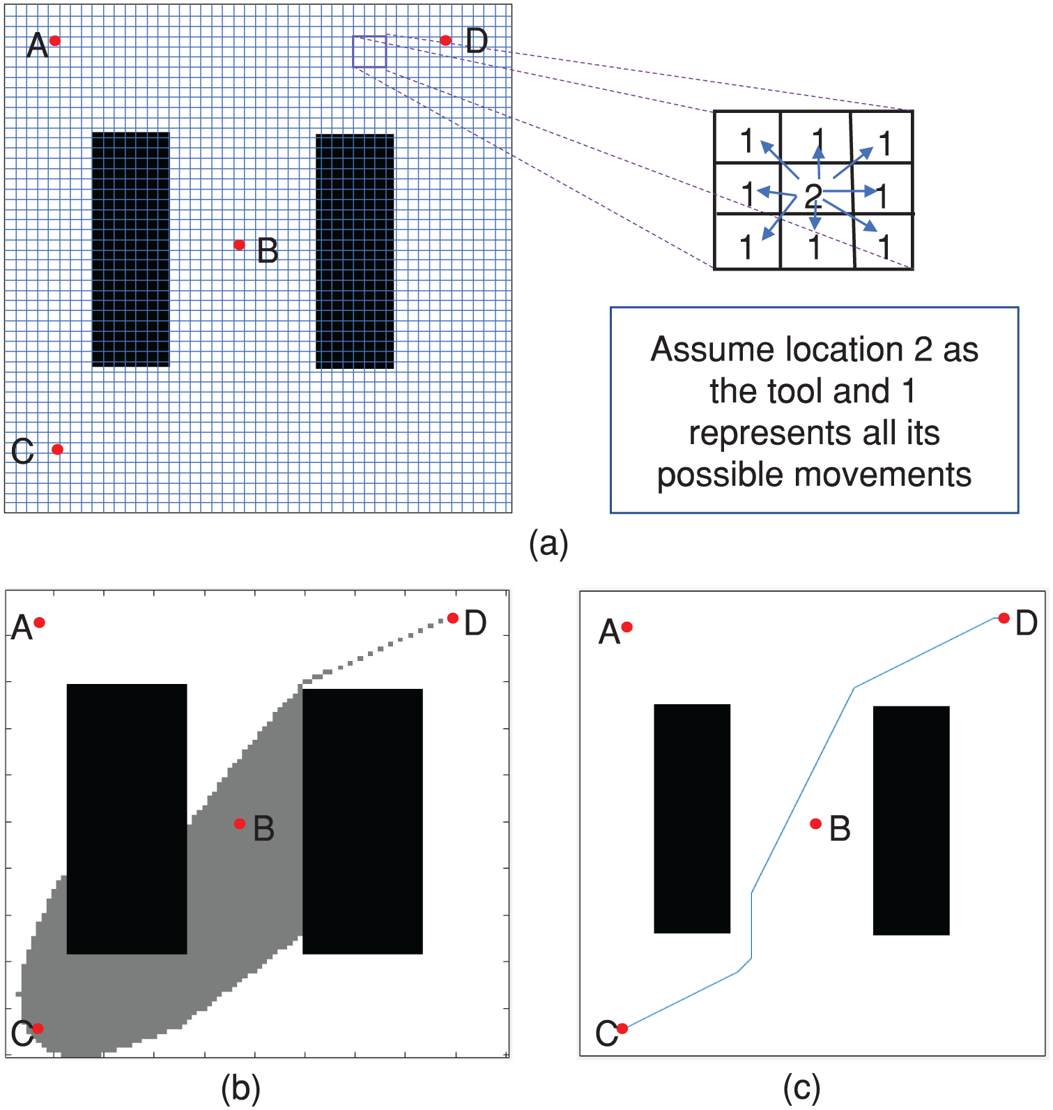
Shortest path calculation between node C and D using A* algorithm: (a) tool movement along with weight matrix, (b) A* algorithm working, and (c) optimum safe cutting tool travel path between two holes.
The cost of movement is calculated by including the weight of the edges which is the Euclidian distance (ED) between connecting points, a heuristic function denoting the nearness of the point, and the ED to the goal. This is shown in Figure 4(c) where A* algorithm is used to find the optimum tool travel path from the initial hole location at C to the goal hole location D. The A* algorithm expands the area of search for every iteration based on the weight matrix which is also indicated in gray color in Figure 4(b), and finally, once it reaches the goal hole location at D, it plots the optimized tool travel path between two hole locations C to D as shown in Figure 4(c), and the distance required by the tool to be traveled is also derived. The same technique is used until all possible combination of holes for this sample such as A to D, A to C, A to B, B to D, and B to C are explored in the area for optimum safe cutting tool travel path as shown in Figure 5(a) represented in color for each pair of holes, and a connection distance matrix is generated as shown in Figure 5(b).

Distance and tool path information between all hole combinations: (a) optimum safe cutting tool travel path between all hole combinations and (b) connection distance matrix.
Finally, based on connection distance matrix, GA is used to generate the near-optimal path of all the holes. For the condition of drilling operation, the drilling tool should start from a predetermined hole location and visit all the hole locations once, in order to complete the operation of drilling before ending at the last hole location with the least total tool traveling distance. The distance information in the connection distance matrix is regarded as a special case of traveling salesman problem where the holes represent the cities and the cutting tool represents the salesman. First, GA generates initial population as B-C-D-A, C-B-A-D, and so on and then calculates the fitness value according to fitness function for each chromosome of the population. Fitness function for this problem is to obtain the minimum path distance for all the holes; hence, it is defined based on the below equation

The path distances for the above-generated initial population are 1360 mm (B-C-D-A) and 1034 mm (C-B-A-D) based on the connection distance matrix shown in Figure 5(b). Clearly, the fitness value for C-B-A-D will be lower based on equation (2). If the optimization criteria are met, then the solution is considered as the best solution, else new population is generated using GA operators of random permutation selection. The best four routes are selected, and random insertion points for crossover are performed. Then, four mutation operators of flip, swap, slide, and do nothing are used in order to generate new population. This process continues for several generations until it converges on optimal or near-optimal solution. Thus, the optimized tool path is acquired where the drilling tool starts from a fixed hole and completes the drilling process at all the hole locations as shown in Figures 6 and 7 with different starting hole locations. The (x, y) coordinates of the tool travel path is then received as an output since each pixel is represented as a node. This will enable CNC machines with less Z-axis travel and higher tool overhang length to use this algorithm and to navigate without collision throughout the machinable areas. The machine selected for this experiment is NHM400 CNC machine which is a student trainer CNC Vertical Machining Center, and the shortest safe cutting tool travel path generated by the algorithm is thus verified in this machine.

Optimized tool travel paths formed by the proposed algorithm for sample 1 with different starting hole locations: (a) starting hole (30, 50), (b) starting hole (250, 250), (c) starting hole (470, 50), and (d) starting hole (30, 450).

Optimized tool travel paths formed by the proposed algorithm for samples 2–4 with different starting hole locations: (a) starting hole (100, 50), (b) starting hole (250, 250), (c) starting hole (400, 50), (d) starting hole (100, 450), (e) starting hole (50, 250), (f) starting hole (140, 70), (g) starting hole (140, 430), (h) starting hole (360, 70), (i) starting hole (150, 112.5), (j) starting hole (350, 112.5), (k) starting hole (250, 40), and (l) starting hole (150, 375).
Experimental results
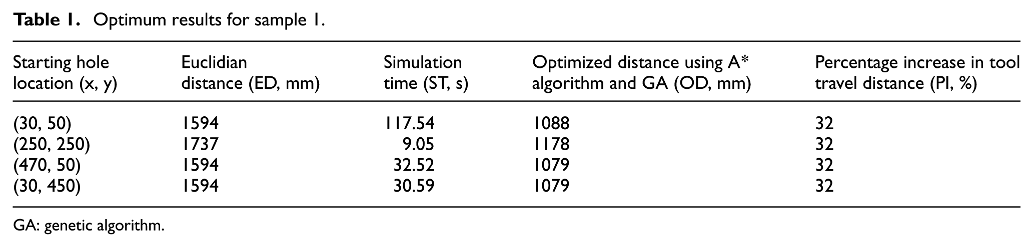
The hole location and tool retraction height of 100 mm are given as input into the system. The hole location is specified in such a way that the origin is set at the top left corner of the image which is explained with sample 2 as shown in Figure 1(b). Sample 1 consists of four holes which are located at different locations. As the previous operation of machining can complete at a location which is near to any of the holes, it is best to fix the starting hole. Hence, the algorithm was tested with different starting hole combinations, and four trials were performed for each starting hole as the GA for each trial gives different simulation time (ST) and different results. Therefore, the average results for each starting hole consisting of ED or the tool travel distance by normal CNC machine, average ST, average optimized distance (OD) using A* algorithm and GA, and average percentage increase (PI) in tool travel distance with respect to the ED are given in Table 1 for sample 1. The results show that when the starting hole for drilling operation is changed, then the distance traveled by the tool ED and distance from the proposed method also changes. The OD from our proposed algorithm is an average value of four trials for each starting hole which was found to be less than ED, and an average of 32% improvement for sample 1 was observed with respect to ED as shown in Table 2. The computational time for each trial is also lower. The resulting optimized tool travel path formed by the proposed algorithm is shown in Figure 6.
Optimum results for sample 1.
GA: genetic algorithm.
Optimum results for all the four samples.

GA: genetic algorithm.
Similarly, the averaged results for all the other three tested samples 2–4 are given in Table 2 which shows an average overall improvement of 38.8%, along with the optimized tool travel path formed by the proposed algorithm as shown in Figure 7, where Figure 7(a)–(d) represents the results generated for sample 2, Figure 7(e)–(h) represents the results generated for sample 3, and Figure 7(i)–(l) represents the results generated for sample 4 which are found to be collision-free optimized travel paths.
In order to test the redundancy of our proposed method, we have tested an extreme case with sample 5 as shown in Figure 8(a) consisting of 108 holes, where the hole locations are generated randomly. These hole locations do not overlap with each other. Sample 5 was tested with three different starting hole locations, and the results are shown in Table 3, where it showed an average overall improvement of 84.66%, and the optimized tool travel path formed by the proposed algorithm is shown in Figure 8(b)–(d). The proposed method reduces airtime, thereby drastically reducing the machining cost. We also found that as the number of holes increased, the average overall improvement also increased. The computational cost of the proposed method was found to be very high compared to the conventional method, and it would require only a few seconds to plot the entire tool travel path. As the proposed method consists of the A* algorithm and GA, they can be processed as a parallel programming model where the computational time would be reduced drastically.

Optimized tool travel paths formed by the proposed algorithm for sample 5 with different starting hole locations: (a) CAD sample, (b) starting hole (196, 319), (c) starting hole (222, 248), and (d) starting hole (374, 143).
Optimum results for sample 5.

GA: genetic algorithm.
Conclusion
The results of the proposed tool path optimization method were compared with the cutting tool travel distance value obtained using the traditional tool path method, whereby the tool travels over the obstacles. On average, an overall improvement was documented in our tested samples. The results were also found to be proportional in such a way that the higher the tool retraction height, the higher the improvement in the reduction of the total tool travel distance. In addition, it was found that the average improvement was directly proportional to the number of holes drilled. The proposed method is expected to be applicable in commercial CAD/CAM packages to minimize the cutting tool airtime and increase the capability of machine tools with short tool retraction heights for automatic generation of CNC machine programs.
Footnotes
Handling Editor: Artde Lin
Declaration of conflicting interests
The author(s) declared no potential conflicts of interest with respect to the research, authorship, and/or publication of this article.
Funding
The author(s) disclosed receipt of the following financial support for the research, authorship, and/or publication of this article: This work was supported by the National Research Foundation of Korea funded by the Korean Government under grant NRF-2016R1A2B4006873.