
Abstract
Many case studies have revealed that rock bursts generally occur in high stress concentration areas where layer-crack structures often exist, especially for brittle coal or rock masses. Understanding the mechanical behavior of layer-crack rocks is beneficial for rational design and stability analysis of rock engineering project and rock burst prevention. This study numerically investigated the influence of vertical fissure geometric configurations on the mechanical behavior of layer-crack rock models through uniaxial compression tests. Results reveal that the deformation and strength behaviors of layer-crack specimens depend on the vertical fissure geometric configurations, which also influence the crack evolution process. In aspect of failure mode, it is splitting failure or shear failure of the whole layer-crack specimen when the fissure length is smaller than 40 mm, but it is splitting failure or shear failure of supporting bodies in other conditions. Among the three factors, the influencing degree in order from strong to weak is fissure number, fissure length, and fissure width. Meanwhile, the influence of fissure geometric configurations on the failure mechanism of layer-crack structure and the occurrence mechanism of rock burst were revealed. In addition, some advices for keeping the stability of layer-crack structure and mitigating rock bursts were given.
Introduction
With the worldwide economic and social development, the shallow mineral resources are gradually depleted, and the depth of mining or tunneling is deeper and deeper.1,2 Under the influence of excavation unloading condition, the deformation and failure modes of deep rock mass is different from that of shallow rock mass, which shows obvious discontinuous and nonlinear characteristics.3,4 Phenomena of layer-crack structure, zonal disintegration, rock burst, and large deformation increase in deep exploitation. The layer-crack structures refer to spalling and slabbing structures of surrounding rock before the occurrence of rock bursts in this article. Case studies have revealed that lots of rock bursts occur in high stress concentration areas where layer-crack structures exist,5–9 as shown in Figure 1. Figure 1(a) is the phenomena of layer-crack structures in brittle rock mass, and Figure 1(b) is the phenomena of layer-crack structures in brittle coal mass. In general, layer-crack structures are closely related with the occurrence of rock bursts in brittle rock or coal mass.

Regarding research on brittle rock mass, theoretical analysis, numerical modeling, laboratory test, and field monitoring methods have been used to study the layer-crack structure and rock burst. In aspect of theoretical analysis, Stacey 10 proposed a simple and empirical criterion for fracture initiation in brittle rock and explained the phenomenon of layer-crack structure formation; Hou et al. 11 theoretically discussed the occurrence mechanism of layer-crack rock bursts; Qiu et al. 12 proposed a comprehensive velocity assessment method to evaluate the rock burst wall-rock velocity evoked by rock slab flexure sources; Weng et al. 13 analyzed the occurrence mechanism and time-dependency effect of layer-crack rock bursts based on the three-parameter viscoelasticity constitutive relationship and the slabbing thin plate mechanical model. In aspect of numerical modeling, Cai 14 concluded that the generation of tunnel surface parallel fractures and micro-cracks was attributed to material heterogeneity and the existence of relatively high intermediate principal stress, as well as zero to low minimum principal stress confinement; Zhang et al. 15 analyzed the influence of intermediate principal stress, stress path, and principal stress axes rotation on the failure mechanism of layer-crack structure using numerical simulation. In aspect of laboratory test, numerous studies investigated the mechanical response of rocks to various loading and unloading conditions, and many layer-crack phenomena before rock bursts in different rocks were reported. For example, He et al.16,17 divided process of granite rock burst into four stages and analyzed the acoustic emission (AE) characteristics during the burst process of limestone through single-face dynamic unloading tests; Gong et al. 5 found that the process of rock burst and the layer-crack failure phenomenon of experimental rock samples were in good accordance with field observations; Zhao et al. 18 studied the influence of unloading rate on the characteristics of strainburst, and test results showed that the layer-crack phenomenon was influenced by the unloading rate; Du et al. 19 summarized the main triaxial loading and unloading tests methods for determining the mechanical behavior of rock materials and researched the layer-crack phenomenon and rock burst induced by true-triaxial unloading and local dynamic disturbance.
Regarding research on brittle coal mass, scholars also have conducted significant work on the layer-crack phenomenon and rock burst. For example, Zhang et al.20,21 found that the occurrence of rock burst in Sanhejian Coal Mine was local instability related to the layer-crack structure and analyzed the formation of layer-crack structure through fracture mechanics and laboratory tests; Peng and Lu 22 studied the formation and failure of layer-crack structure of surrounding rock under the influence of stress waves using LS-DYNA software; Bai et al. 23 presented three numerical models, that is, intact coal wall and coal wall including vertical discontinuities and criss-cross discontinuities, to investigate the failure mechanism of layer-crack structure of the coal wall based on extensive field surveys; Mohamed et al. 7 found that there exist obvious layer-crack structures in the coal wall face through analyzing the current rib support practices in 20 coal mines in the United States.
Obviously, scholars have reached a consensus that layer-crack structures make an essential contribution to rib spalling or rock burst in brittle coal or rock masses.7,24–30 As shown in Figure 2, the occurrence mechanism can be described as follows:31,32 first, the layer-crack structure forms under the compression stress concentration of surrounding rock induced by the excavation unloading, as shown in Figure 2(a) and (b); second, the compression stress concentration further leads to the buckling deformation of layer-crack plates and to the continuous accumulation of strain energy stored in layer-crack plates, as shown in Figure 2(c); third, when the strain energy stored in layer-crack plates reaches the storage limit, dynamic instability might take place under the influence of external disturbance, as shown in Figure 2(d).

Schematic diagram of the occurrence mechanism of rock burst: 31 (a) crack initiation and propagation, (b) formation of the layer-crack structure, (c) strain energy accumulation, and (d) occurrence of dynamic instability.
As a consequence of the above researches, the meaningful results provide a good reference for understanding the mechanism of layer-crack structure formation. Above researches mainly focus on the formation of layer-crack structure and the related influencing factors. Although the viewpoint that layer-crack structure often exists before the occurrence of rock burst is widely accepted by scholars, there are few literatures trying to study the influence of vertical fissure geometric configurations on the mechanical properties of layer-crack specimens. In addition, the process shown in Figure 2(c) and (d) still needs to be further detailed research. Therefore, a systematic numerical simulation by PFC2D was performed to research the mechanical properties of layer-crack specimens with different vertical fissure geometric configurations under uniaxial compression tests. Before this simulation process, the micro-parameters simulated for the layer-crack specimen are first confirmed based on the experimental results of rock-like specimen. At last, the influence of vertical fissure geometric configurations on the failure mechanism of layer-crack structure was discussed based on the numerical results, and then, the occurrence mechanism of rock burst related to the layer-crack structure was revealed. At the same time, some advices for keeping the stability of layer-crack structure and mitigating rock bursts were given.
Discrete element model and micro-parameters
Discrete element model
Micro-bond model
In PFC2D, there are two kinds of failure modes between particles, including shear failure and tension failure. It has two different bond models contact-bond model (CBM) and parallel-bond model (PBM) generally used for simulating granular materials and compact materials, respectively. There are two advantages for PBM: first, parallel bonds can transmit both forces and moments between particles; second, bond breakage can lead to immediate decrease in macro stiffness. Thus, PBM can be more realistic for simulating rock material because the bonds can break in either tension or shearing as the stiffness reduces.33,34 In this article, we chose PBM to carry out the numerical simulation.
Numerical layer-crack specimen and simulation procedure
The height and width of numerical specimen were 100 and 50 mm, respectively. The numerical specimen was discretized into 11,693 particles. The particle size followed a uniform distribution varying from 0.3 to 0.4 mm. The average unit of rock-like material was about 1600 kg/m3. After generating the specimen, we established layer-crack rock models by deleting ball particles. The vertical fissure geometry is mainly described by three parameters, including fissure length, fissure width, and fissure number (Note that the term “fissure” is used to describe the artificially created flaw or crack, and the term “crack” is adopted to describe the new fracture or failure in the loading process), because the research object of this article is the layer-crack rock model, which means the fissure angle is 90°. As shown in Figure 2, during the formation of rock bursts induced by the layer-crack structure, these vertical fissures first initiated and propagated and then formed the layer-crack structure. During this process, the fissure length, fissure number, and fissure width might vary greatly. Thus, in order to investigate the influence of vertical fissure geometric configurations on the strength, deformation, and failure mechanism of layer-crack specimens in detail, we designed three kinds of test schemes, that is, scheme I considering the influence of fissure length, scheme II considering the influence of fissure width, and scheme III considering the influence of fissure number, as shown in Figure 3. In scheme I, the fissure width and fissure number are set to 1 mm and 1, respectively, while the fissure length varies from 20 to 80 mm, as shown in Figure 3(a). In scheme II, the fissure length and fissure number are set to 80 mm and 1, respectively, while the fissure width varies from 0.5 to 2.5 mm, as shown in Figure 3(b). In scheme III, the fissure width and fissure length are set to 1 and 80 mm, respectively, while the fissure number varies from 1 to 4, as shown in Figure 3(c). Detailed description of layer-crack specimens with different vertical fissure geometric configurations under uniaxial compression tests is listed in Table 1.

Layer-crack specimens with different vertical fissure geometric configurations: (a) layer-crack specimens with different fissure lengths, (b) layer-crack specimens with different fissure widths, and (c) layer-crack specimens with different fissure numbers.
Layer-crack specimens with different vertical fissure geometric configurations.

An external displacement was applied on the top of the specimens in the axial direction. The loading rate must be low for ensuring the specimen remained in a quasi-static state throughout the simulation process. Zhang and Wong 35 researched the influence of loading rate on the mechanical behavior of specimens containing pre-fissures, which showed that the crack initiation stress and uniaxial compressive strength remained steady when the loading rate increased from 0.005 to 0.08 m/s. Therefore, the loading rate of 0.05 m/s was chosen in this numerical simulation, and the loading was applied until the failure occurred.
Confirmation for micro-parameters of rock-like material
Confirming method for micro-parameters
Determining the micro-parameters for numerical simulation is difficult by experiment. However, it is very essential to establish a correlation between macro-behavior and micro-parameters for validating the particle properties used in numerical specimens. The macro-behavior includes the axial strain curve, the peak stress, the elastic modulus, and the failure mode. The trial and error method was used in confirming the micro-parameters. 36 The macro-behavior of rock-like material obtained by experiment was used to calibrate the micro-parameters. After each trial, the macroscopic results obtained by numerical simulation were used to compare with the experimental results. This process was repeated until the numerical results were similar to the experimental results.
The micro-parameters used in PFC2D model are listed in Table 2. The elastic modulus of the particle is 1.4 GPa. The ratio of normal to shear stiffness of the particle and the parallel bond is 2.5. The particle friction is 0.5. The values of parallel-bond normal strength (σn) and parallel-bond shear strength (τn) are 12.5 and 15.0 MPa, respectively.
Micro-parameters used in the PFC2D model.

Calibration of micro-parameters by experimental results
The comparison between experimental and numerical stress–strain curves under uniaxial compression is shown in Figure 4. It can be seen that both the numerical curve and the experimental curve include elastic deformation stage, crack initiation and growth stages, and unstable failure stage. However, the experiment specimen also has the stage of compaction and nonlinear deformation at low stress levels, which are not observed in the numerical specimen. This is because the experimental specimen contains primary cracks, pores, and voids.

Comparison between experimental and numerical stress–strain curves under uniaxial compression.
The comparison of mechanical parameters between the experimental results and numerical results is listed in Table 3. In Table 3, σc is defined as the uniaxial compressive strength, and E refers to the slope of the linear part of the stress–strain curve. In accordance with Table 3, it shows clearly that the simulated peak stress and elastic modulus are almost equal to those obtained by the experiment.
Comparison between the experimental and numerical mechanical parameters.

The comparison between the experimental and numerical failure modes is depicted in Figure 5. Figure 5 illustrates that the failure mode of rock-like specimen is axial splitting under numerical simulation, which is similar to that obtained by experiment. The comparisons shown in Figures 4 and 5 calibrate the rightness and reasonability of micro-parameters used in Table 2.
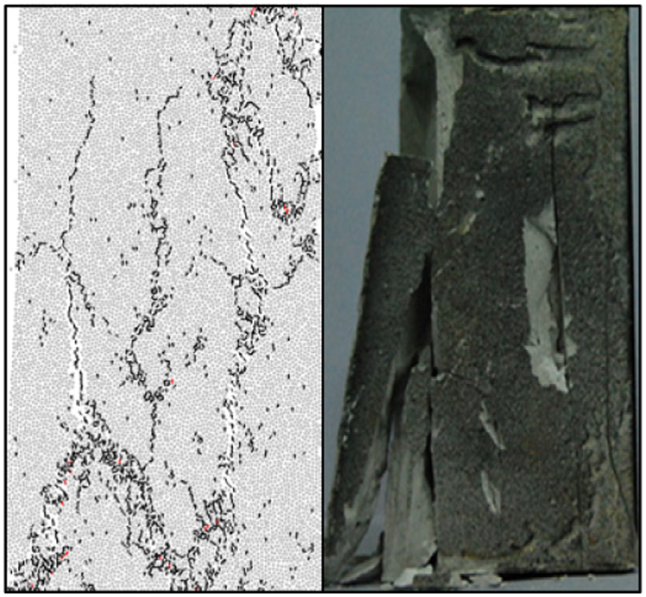
Comparison between experimental and numerical failure modes of rock-like material under uniaxial compression test (the black and red dots represent the tensile micro-crack and shear micro-crack, respectively).
Numerical results of layer-crack rock models with different vertical fissure geometric configurations
Overall stress-strain curves
Stress–strain curves of layer-crack specimens with different vertical fissure geometric configurations under uniaxial compression are shown in Figure 6. In accordance with Figure 6, we can conclude that the yield stress and compression strength of layer-crack specimens decrease gradually as the fissure length or the fissure number except the fissure width increases, which will be analyzed in detail in the following.

Stress–strain curves of layer-crack specimens with different vertical fissure geometric configurations under uniaxial compression: (a) different fissure lengths, (b) different fissure widths, and (c) different fissure numbers.
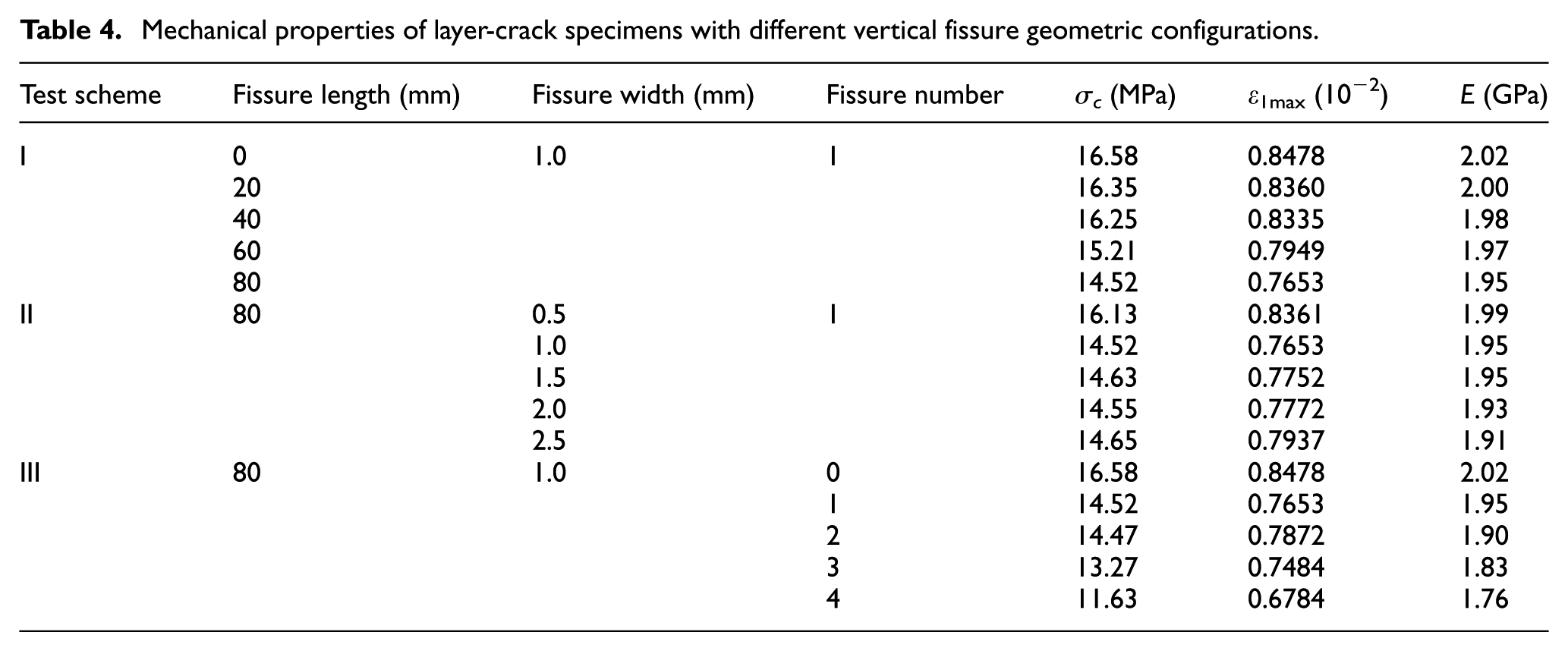
Table 4 lists the mechanical properties of layer-crack specimens, that is, peak stress (σ1max), the elastic modulus (E), and the peak axial strain (ε1max) corresponding to the strain at peak stress. In accordance with the numerical results listed in Table 4, generally, the deformation and strength behaviors of layer-crack specimens are found depending on the vertical fissure geometric configurations, especially the fissure number.
Mechanical properties of layer-crack specimens with different vertical fissure geometric configurations.
Influence of fissure length
Figure 7 shows the influence of fissure length on the mechanical properties of layer-crack specimens, and number zero means intact specimen. From Figure 7, it can be seen that the elastic modulus and peak strain almost keep stable with the increase in fissure length. Specifically, when the fissure length increases from 20 to 80 mm, the elastic modulus varies from 1.95 to 2.00 GPa and the peak strain varies from 0.8360 to 0.7653 × 10⁻², respectively. However, the uniaxial compressive strength shows a different trend. The uniaxial compressive strength keeps stable when the fissure length increases from 20 to 40 mm, but decreases rapidly from 16.25 to 14.52 MPa when the fissure length increases from 40 to 80 mm. This result shows that the fissure length does not influence the deformation parameters of layer-crack specimens obviously, but influences the strength parameter, especially when the vertical fissure length is larger than 40 mm.
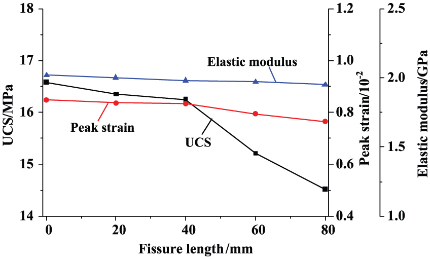
Influence of fissure length on the mechanical properties of layer-crack specimens.
To understand the influence of fissure length on the failure process of layer-crack specimens, the crack evolution of layer-crack specimens with different fissure lengths is given in Figure 8. From Figure 8, we can find that the process of crack evolution for these specimens can be divided into four stages, that is, quiet stage, minor stage, major active stage, and stable stage. Take the crack evolution process of layer-crack specimen with fissure length 80 mm as an example for explaining the four stages, as shown in Figure 8(b). In the quiet stage corresponding to the elastic deformation stage, no cracks could be recorded. However, the number of cracks increases slowly in the minor stage, which means the loading process comes into the yield stage. The cracks continue growing rapidly after the minor stage, which means that the crack evolution comes into the major active stage. In this stage, the inner damage of the specimen develops until reaching the unstable failure and then following the stable stage. From Figure 8(a), it can be found that the fissure length mainly influences the time when coming into the major active stage, especially for fissure lengths 60 and 80 mm. When the fissure length increases from 20 to 40 mm, the starting strain of major active stage remains stable, which is 0.8334 × 10⁻². However, the starting strain of major active stage decreases from 0.8334 to 0.7404 × 10⁻² as the fissure length increases from 40 to 80 mm.

Influence of fissure length on the crack evolution of layer-crack specimens: (a) crack evolution of specimens with different fissure lengths and (b) crack evolution of specimen with fissure length 80 mm.
Overall, the results above reveal that the mechanical properties of layer-crack specimens will be influenced strongly if the fissure length is larger than 40 mm. As the fissure length continues increasing from 40 mm, both the bearing capacity and the starting time of major active stage decrease rapidly. In other words, when the fissure length is smaller than 40 mm, the mechanical properties of layer-crack specimen are similar to intact specimens. Therefore, choosing the fissure length 80 mm in test schemes II and III is reasonable.
Influence of fissure width
Figure 9 shows the influence of fissure width on the mechanical properties of layer-crack specimens. From Figure 9, it can be seen that the elastic modulus and peak strain almost keep stable with the increase in fissure width, whose variation law is similar to the influence of fissure length. For example, when the fissure width increases from 0.5 to 2.5 mm, the variations in elastic modulus and peak strain are 1.91–1.99 GPa and 0.7937–0.8361 × 10⁻², respectively. The uniaxial compressive strength is only influenced when the fissure width increases from 0.5 to 1.0 mm, and the uniaxial compressive strength decreases from 16.13 to 14.52 MPa. As increasing the fissure width from 1.0 to 2.5 mm, the uniaxial compressive strength keeps stable. This result shows that the fissure width only influences the strength parameter of layer-crack specimens when the fissure width is smaller than 1.0 mm.

Influence of fissure width on the mechanical properties of layer-crack specimens.
To understand the influence of fissure width on the failure process of layer-crack specimens, the crack evolution of layer-crack specimens with different fissure widths is given in Figure 10. The process of crack evolution for these specimens also includes four stages, which is similar to Figure 8(b). The fissure width also mainly influences the starting time of major active stage, especially when the fissure width is smaller than 1 mm. For example, the starting time of major active stage decreases from 0.8295 to 0.7529 × 10⁻² as increasing the fissure width from 0.5 to 1 mm, but as the fissure width continues increasing, the starting time remains stable.
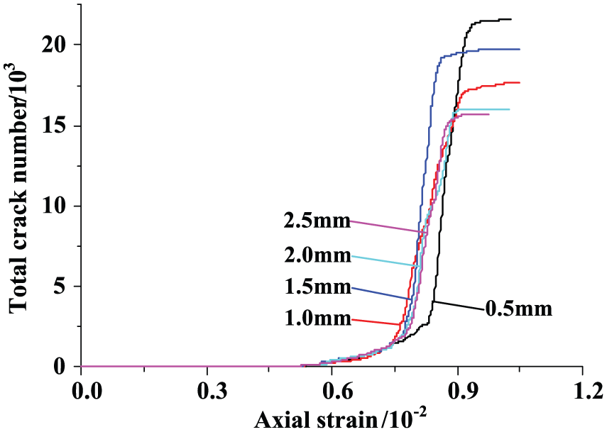
Influence of fissure width on the crack evolution of layer-crack specimens.
The results above reveal that the mechanical properties of layer-crack specimens will be influenced if the fissure width is smaller than 1 mm. As the fissure width continues increasing from 1 mm, the mechanical properties of layer-crack specimens remain stable. Therefore, choosing the fissure width 1 mm in test schemes I and II is suitable.
Influence of fissure number
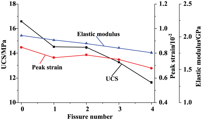
Figure 11 shows the influence of fissure number on the mechanical properties of layer-crack specimens, and number zero means intact specimen. From Figure 11, it can be seen that both the deformation and strength parameters are obviously influenced by the fissure number. On the whole, the elastic modulus, the peak strain, and the uniaxial compressive strength all decrease as increasing the fissure number. When the fissure number increases from 0 to 4, the elastic modulus, the peak strain, and the uniaxial compressive strength all decrease from 2.02 to 1.76 GPa, 0.8478 to 0.6784 × 10⁻², and 16.58 to 11.63 MPa, respectively. This result reveals that the bearing capacity of layer-crack specimens decreases, which means that the instability probability is higher for layer-crack structure, as increasing the fissure number.
Influence of fissure number on the mechanical properties of layer-crack specimens.
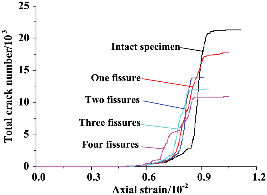
To understand the influence of fissure number on the failure process of layer-crack specimens, the crack evolution of layer-crack specimens with different fissure numbers is given in Figure 12. From Figure 12, it can be seen that the fissure number strongly influences the crack evolution process of layer-crack specimens. When the fissure number increases from 0 to 4, the starting time of major active stage decreases from 0.8334 to 0.6771 × 10⁻² and the total crack number decreases from 2102 to 1072. From the point of crack evolution, it again illustrates that the risk of dynamic instability for layer-crack structure increases as the number of vertical fissure increases.
Influence of fissure number on the crack evolution of layer-crack specimens.
Discussions
Although significant work has been done on the formation process of layer-crack structure and rock burst, there is little work trying to explain the influence of vertical fissure geometric configurations on the stability of layer-crack structure in detail. Therefore, this part first tries to reveal the influence of fissure length, fissure width, and fissure number on the failure mechanism of layer-crack structure based on the numerical results. Figure 13 gives the failure modes of layer-crack specimens with different fissure geometric configurations. Then, the occurrence mechanism of rock burst related to the layer-crack structure is also discussed.
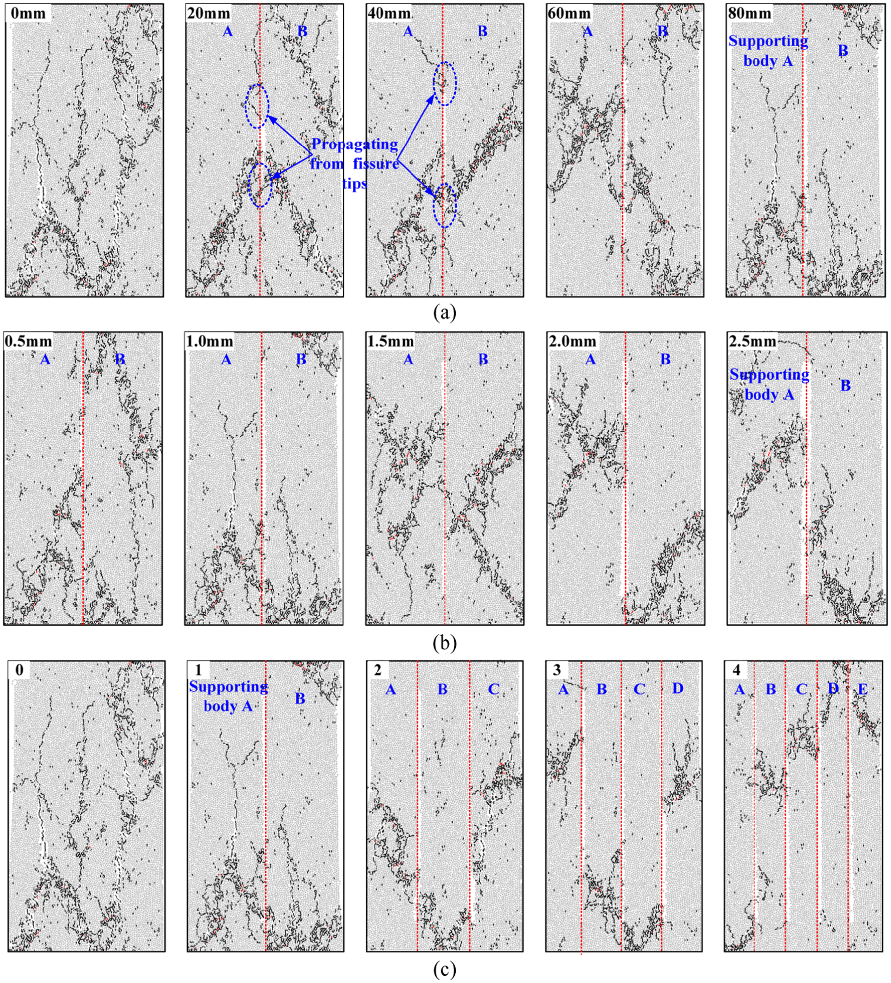
Failure modes of layer-crack specimens with different fissure geometric configurations: (a) layer-crack specimens with different fissure lengths, (b) layer-crack specimens with different fissure widths, and (c) layer-crack specimens with different fissure numbers.
Influence of fissure length on the failure mechanism
Figure 13(a) shows that when the fissure length is smaller than 40 mm, the failure mode of layer-crack specimens is splitting failure or shear failure of the whole specimen, which is similar to intact specimens, while when the fissure length is larger than 40 mm, the failure mode is splitting failure or shear failure of the supporting bodies (i.e. the part of the specimen is divided by the vertical fissure). In addition, we can also find that when the fissure length is smaller than 40 mm, cracks mainly propagate from the fissure tips, which is not seen when the fissure length is larger than 40 mm. The two phenomena illustrate that the fissure length influences not only the failure mechanism of layer-crack structure but also the crack propagation.
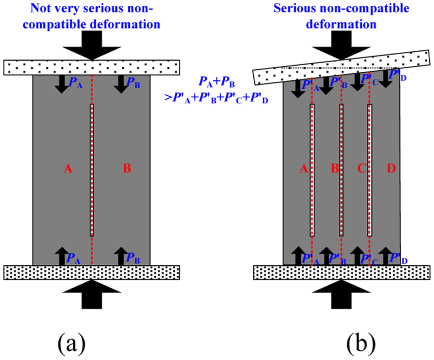
Therefore, the influence of fissure length on the failure mechanism of layer-crack structure is as follows: when the fissure length is smaller than a certain value, it is still integral bearing of the whole layer-crack structure, as shown in Figure 14(a); but when the fissure length is larger than a certain value, the integral bearing of the whole translates into the common bearing of supporting bodies A and B, as shown in Figure 14(b). However, the bearing capacity (P) of the whole layer-crack structure is larger than the common bearing capacity (PA + PB) of supporting bodies A and B, which is proved in section “Influence of fissure length.” That is to say, the unstable stability of layer-crack structure might occur if the vertical crack growth is not controlled in time, which indicates that controlling the crack growth can enhance the bearing capacity of layer-crack structure.

Schematic diagram of the bearing of layer-crack structures with different fissure lengths: (a) fissure length smaller than a certain value and (b) fissure length larger than a certain value.
Influence of fissure width on the failure mechanism
Figure 13(b) shows that the failure mode of layer-crack specimens with different fissure widths is splitting failure or shear failure of the supporting bodies. The splitting failure exists among the two supporting bodies when the fissure width is smaller than 1.0 mm, but disappears when the fissure width is larger than 1.0 mm. Results in section “Influence of fissure width” show that the bearing capacity and mechanical properties of layer-crack specimens remain stable as the fissure width is larger than 1.0 mm. In other words, the compatible deformation ability of supporting bodies decreases as the fissure width increases to a certain value and then remains stable.
Therefore, the influence of fissure width on the failure mechanism is as follows: when the fissure width is smaller than a certain value, the common bearing ability of supporting bodies A and B is good, as shown in Figure 15(a); but when the fissure width is larger than a certain value, the common bearing ability of supporting bodies A and B is really bad, inducing the sharp decrease in the bearing capacity of layer-crack structure, as shown in Figure 15(b). This result illustrates that when the crack width reaches a certain value, it might be impossible for enhancing the bearing capacity of layer-crack structure. Although controlling the crack width can also enhance the bearing capacity of layer-structure in some conditions, but seems unsatisfactory compared with controlling the crack growth.

Schematic diagram of the bearing of layer-crack structures with different fissure widths: (a) fissure width smaller than a certain value and (b) fissure width larger than a certain value.
Influence of fissure number on the failure mechanism
Figure 13(c) shows that the
failure mode of layer-crack specimens with different fissure numbers is the splitting
failure or shear failure of supporting bodies. The splitting failure exists among the two
supporting bodies when the fissure number is smaller than 2, but disappears when the
fissure number is larger than 2. Moreover, results in section “Influence of fissure
number” show that the bearing capacity of layer-crack specimen decreases rapidly as
increasing the fissure number, indicating that the bearing capacity
Schematic diagram of the bearing of layer-crack structures with different fissure numbers: (a) fissure number smaller than a certain value and (b) fissure number larger than a certain value.
Therefore, the influence of fissure number on the failure mechanism is as follows: when the fissure number is small, the degradation of the common bearing ability of supporting bodies is not serious, as shown in Figure 16(a); but when the fissure number continues increasing, the degradation of common bearing ability of supporting bodies becomes more and more serious, inducing the risk of unstable instability for increase in layer-crack structure, as shown in Figure 16(b). In other words, if the number of supporting bodies in the layer-crack structure is not controlled, the risk of unstable instability will increase greatly. Obviously, controlling the fissure number is an excellent way for keeping the stability of layer-crack structure.
Occurrence mechanism of rock burst
The influence of vertical fissure geometric configurations on the failure mechanism of layer-crack structure has been discussed above. This section mainly discusses the occurrence mechanism of rock burst related to the layer-crack structure.
First, the rock or coal wall can be simplified into two major parts, such as layer-crack structure and intact structure, as shown in Figure 17(a), because layer-crack structures often exist in rock burst areas. Then, based on the results in section “Numerical results of layer-crack rock models with different vertical fissure,” the stress curves of layer-crack structure and intact structure (under lateral constraint of layer-crack structure) can be depicted as shown in Figure 17(b) corresponding to Figure 17(a). So far, Figure 17(a) and (b) gives the simple combination system of layer-crack structure and intact structure for rock or coal wall before the occurrence of rock burst. As shown in Figure 17(a) and (b), when a vertical strain ε, which is smaller than ε0, acts on the system, it can be assumed that the stresses acting on the layer-crack structure and intact structure are σA and σB, respectively. Before the dynamic instability, obviously the stress σA is smaller than the peak stress σL of the layer-crack structure, and the whole combination system is in a dynamic balancing state.
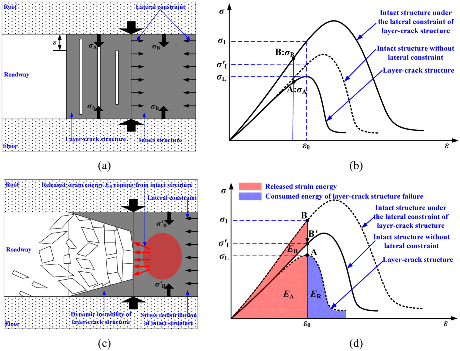
Schematic diagram of the occurrence mechanism of rock bursts related to the layer-crack structure: (a) combination system of the layer-crack structure and intact structure (under lateral constraint of layer-crack structure) of roadway before the occurrence of rock burst, (b) stress curves of the layer-crack structure and intact structure before the occurrence of rock burst, (c) dynamic instability of the layer-crack structure and the rock burst, and (d) stress redistribution of the intact structure after the occurrence of rock burst.
As the vertical strain ε continues increasing, both the stress σA and σB increase until reaching the peak stress σL of the layer-crack structure, as shown in Figure 17(d). When the stress σA acting on the layer-crack structure is larger than σL, the layer-crack structure will experience the dynamic instability, as shown in Figure 17(c). At the same time, the lateral constraint of layer-crack structure acting on the intact structure is relieved, inducing the stress redistribution of the new system. As shown in Figure 17(d), the stress point of intact structure moves from B to B′, leading to the release of some strain energy EB stored in the intact structure. Therefore, when a rock burst related to the layer-crack structure occurs, the impact energy EI can be calculated by

where EA is the energy stored in the layer-crack structure and ER is the energy consumed by the layer-crack structure failure. One thing needs to be pointed is that the instability of layer-crack structure means the instability of roadway, which means we should not decrease the bearing capacity of the layer-crack structure. Thus, the only way is to reduce the strain energy EB stored in the deep rock or coal wall based on equation (1).
Overall, the occurrence mechanism of rock burst related to the layer-crack structure is given in Figure 17. Based on this mechanism, we can conclude that there are two basic guidelines for mitigating rock bursts related to the layer-crack structure. First, enhancing the bearing capacity of the layer-crack structure, as illustrated in sections “Influence of fissure length on the failure mechanism,”“Influence of fissure width on the failure mechanism,” and “Influence of fissure number on the failure mechanism”; second, decreasing the bearing capacity of the intact structure and reducing the strain energy storied in the deep rock or coal wall.
Conclusion
In this article, the micro-parameters simulated for layer-crack specimens are first confirmed based on the experimental results of rock-like specimen. By comparing the simulated results with the experimental results, we found that the numerical results were in good agreement with the experimental results. Then, a systematic numerical simulation by PFC2D was performed to research the mechanical properties of layer-crack specimens with different vertical fissure geometric configurations under uniaxial compression tests. Based on the simulated results, the influence of vertical fissure geometric configurations on the failure mechanism of layer-crack structure and the occurrence mechanism of rock burst related to the layer-crack structure were discussed. The following conclusions can be summarized.
The elastic modulus and peak strain almost keep stable for layer-crack specimens with different fissure lengths, and the uniaxial compressive strength also keeps stable when the fissure length increases from 20 to 40 mm, but decreases from 16.25 to 14.52 MPa when the fissure length increases from 40 to 80 mm. In addition, the fissure width also influences the starting time of the major active stage during the crack evolution process, especially when the fissure length increases from 40 to 80 mm, the starting strain decreases from 0.8334 to 0.7404 × 10⁻².
The elastic modulus and peak strain almost keep stable with the increase in fissure width. However, the uniaxial compressive strength decreases from 16.13 to 14.52 MPa when the fissure width increases from 0.5 to 1.0 mm and then remains stable when the fissure width continues increasing, which is similar to the variation law of starting time of major active stage during the crack evolution process.
On the whole, the elastic modulus, the peak strain, the uniaxial compressive strength and the starting time of major active stage for layer-crack specimens all decrease as the fissure number increases. Specifically, when the fissure number increases from 0 to 4, the elastic modulus, the peak strain, the uniaxial compressive strength and the starting time decrease from 2.02 to 1.76 GPa, 0.8478 to 0.6784 × 10⁻², 16.58 to 11.63 MPa, and 0.8334 to 0.6771 × 10⁻², respectively.
In the aspect of failure mode, it is splitting failure or shear failure of the whole specimen when the fissure length is smaller than 40 mm, which is similar to intact specimens. The failure mode, however, is all splitting failure or shear failure of supporting bodies for layer-crack specimens in other conditions.
Based on the research about the influence of vertical fissure geometric configurations on the mechanical properties of layer-crack specimens, we can conclude that the bearing capacity of layer-crack structure decreases as increasing the fissure length, fissure width, or fissure number. Among the three factors, the influencing degree in order from strong to weak is fissure number, fissure length, and fissure width. Controlling the vertical crack number and crack growth is a good way for keeping the stability of layer-crack structure.
The occurrence mechanism of rock burst related to the layer-crack structure can be described as follows. First, the rock or coal wall can be simplified into two major parts, that is, layer-crack structure and intact structure. The intact structure is under the lateral constraint of layer-crack structure before the occurrence of rock burst. Second, when the layer-crack structure experiences dynamic instability, the lateral constraint of layer-crack structure acting on the intact structure is relieved, inducing the stress redistribution of intact structure. At the same time, some strain energy stored in the intact structure is released to participate in the dynamic instability of layer-crack structure. At last, a rock burst occurs due to the dynamic instability of layer-crack structure and the energy release of intact structure.
Although the above-mentioned analysis results all were obtained by numerical simulation, it still reveals some variation laws about the influence of fissure length, fissure width and fissure number on the mechanical properties and failure mechanisms of layer-crack specimens. The homogeneity of rock or rock-like materials is often hard to be controlled, but in the PFC2D numerical simulation process, the material is homogeneous during the testing process. Thus, the variation laws of mechanical properties of layer-crack specimens with different geometric configurations could be revealed without the influence of other factors, especially the material differences. Therefore, the results obtained in this article can also provide references for rock bursts control related to the layer-crack structure. Of course, we will continue to do laboratory tests in the future to enrich the researches about the stability of layer-crack structure.
Footnotes
Handling Editor: Jianqiao Ye
Declaration of conflicting interests
The author(s) declared no potential conflicts of interest with respect to the research, authorship, and/or publication of this article.
Funding
The author(s) disclosed receipt of the following financial support for the research, authorship, and/or publication of this article: The research described in this article was financially supported by State Key Research Development Program of China (No. 2016YFC0801401), National Natural Science Foundation of China (Nos 51674160, 51474137, and 51604165), Taishan Scholar Engineering Construction Fund of Shandong Province of China, and Taishan Scholar Talent Team Support Plan for Advantaged & Unique Discipline Areas, and Open Fund Research Project of State Key Laboratory Breeding Base for Mining Disaster Prevention and Control (No. MDPC201711).