
Abstract
To solve problems associated with the processing of PC steel bars, such as continuous cutting, fracture oil, and low sizing precision, an online sizing cutting scheme using an oscillating follower cam and based on mechanical electro-hydraulic integration is proposed. The technique structure of the oscillating follower cam cutting system is outlined. The motion law of the oscillating follower was analyzed with a cam mechanism to inform the design of a conjugate cam. A parameter selection principle for the conjugate cam cutting mechanism with oscillating follower is proposed and employs the parametric proportional coefficient method. A dynamic model with clearance is established, and the dynamic performance is analyzed. A three-dimensional entity model of the cam cutting mechanism with oscillating follower is built, and dynamic simulation and prototype testing are conducted on this model. The results show that the mechanism meets the engineering requirements and has the advantages of simple structure and high cutting precision. This research forms the theoretical basis for online sizing cutting cam mechanisms and outlines effective design methods for the development of new products.
Introduction
Steel bars are widely used in pre-stressed concrete components, such as high strength pre-stressed concrete pipe piles, centrifugal poles, viaduct piers, and railway sleepers. With the improvement of automaticity, new technical requirements for the shearing machining of PC steel bars, including high accuracy of sizing cutting and reliability of online work performance, 1 have been proposed, and the defining factor of the shear mechanism design is the repetition accuracy of the shear action. The conjugate cam belongs to the closed cam mechanism and has small impact, high rigidity, precise motion control, and compact structure.2,3 The conjugate cam can be used in a rotary reciprocating oscillating arm mechanism, 4 which is a reliable, continuous, dynamic, and high precision derivative of the cam cutting mechanism with oscillating follower with a simple drive input. 5
Recent achievements in the study of the conjugate cam mechanism have led to improvements in the design of its mechatronics. In actual working conditions, abrasion causes the gap between the friction pair of conjugate cam mechanisms to widen, which leads to decreased cutting accuracy, the production of an additional dynamic load, increased vibration and noise, and even malfunction or failure. The influence of surface roughness, assembly, and gap size of each component on the dynamic characteristics of a cam system was analyzed in Song et al. 6 The design flow was reorganized and arranged, and a cam dynamic optimization method for a parametric prototype using the parametric modeling technology MSC.ADAMS was proposed in Tsai. 7 Considering the flexibility and friction of the cam shaft between the cam and push rod, the dynamic equation of an eccentric cam mechanism was established using the finite element method and the Lagrange equation in Zhang and Zhang. 8 While cam mechanism models tend to be accurate and practical, and theories concerning complex factors, such as damping and clearance, have gradually been developed, such theories and their application to engineering problems warrant further investigation.
In this article, an online sizing cutting scheme of oscillating follower cam for PC steel bars was proposed based on mechanical electro-hydraulic technology. The key factor of repeated positioning accuracy of the shear action was investigated. Based on conjugate cam transmission theory, a parameter selection principle of the conjugate cam cutting mechanism with oscillating follower was outlined using the parametric proportional coefficient method. Dynamic simulation and prototype testing were conducted, and the design method of the cam cutting mechanism with oscillating follower was developed. Online sizing cutting of large PC steel bars was realized.
Working principle of online sizing cutting system
The cutting mechanism of an oscillating follower cam relies on impact shear introduced via a periodic system of “start and stop,” starting from when the steel bars move to the setting length. The cutting mechanism automatically and accurately returns to the initial position and waits for the next working period after the steel bars are cut off, and this process meets the requirements of standard automation technology for cutting steel bars. To solve the continuous cutting problem associated with hammer cutting and to avoid oil contamination from the structure during hydraulic cutting, the cutter is controlled by a cam lever pair and a hydraulic system in the cutting mechanism. The working principle of the sizing cutting system is shown in Figure 1. The flywheel on the main shaft rotates continuously and is driven by a motor. After the sizing device is initiated by the steel bar, the positioning switch sends cutting signals to the PLC and later to an electromagnetic directional valve controlled by a PLC-connected conversion valve. High-pressure oil flows through the rotary joint to the hydraulic clutch brake, releasing the brake pads and clutch disc mesh. The main shaft is driven by a flywheel so that the mechanism can achieve the cutting action. The traction roller produces a short skid during the entire cutting process of the steel bars, and after the cutter is switched off, the steel bar continues to move on. A photoelectric position detector with two synchronization loops is applied, and the two loops are connected to the main shaft and rotated with a phase difference of 15°. The left synchronization loop passes through the proximity switch first, sending a separation signal to the PLC, which controls the solenoid valve and loosens the clutch disc. When the right synchronization loop passes through the proximity switch, the brake signal is sent to the PLC, and the brake friction plate mesh and main shaft both stop turning. After one cutting period is completed, the next working period commences. The repeated positioning accuracy of the cutting mechanism is guaranteed, since the continuous high-frequency reciprocating swing of the conjugate cam mechanism is converted to a single swing in the cutting period; thus, high cutting precision is achieved.
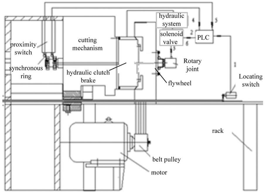
Working principle of the sizing cutting system.
Parameter design of conjugate cam mechanism
To meet the technical requirements of the production line and realize the online sizing cutting of PC steel bars, the plate type of the conjugate cam mechanism with roller follower is applied. A schematic diagram of this mechanism is shown in Figure 2. The cutter is needed to accomplish quick-return motion after the cutting action is completed for the purpose of reducing the impact of the steel bars on the cutter. Any sort of impact needs to be avoided at the starting and ending point of the motion, and this is crucial for selecting the combination type motion law curve in the design of the cam mechanism. The process of shearing, quick-return and suspension for the upper cutter correspond to the rise, return, and inner dwell of the main cam, respectively.

Disk conjugate cam mechanism with roller follower.
Selection of cam curve
The characteristic of the cam curve directly affects the cam mechanism’s dynamic performance, efficiency, and operational life span. The single-dwell-modified sine curve possesses excellent characteristics, such as small maximum dimensionless speed, smooth curve changes, a terminal degree of 0, small residual vibrations, compact structure of the cam mechanism, and high transmission efficiency.
9
In the motion curve of the cam follower, the angle of the stroke of the swing rod is
In the push period


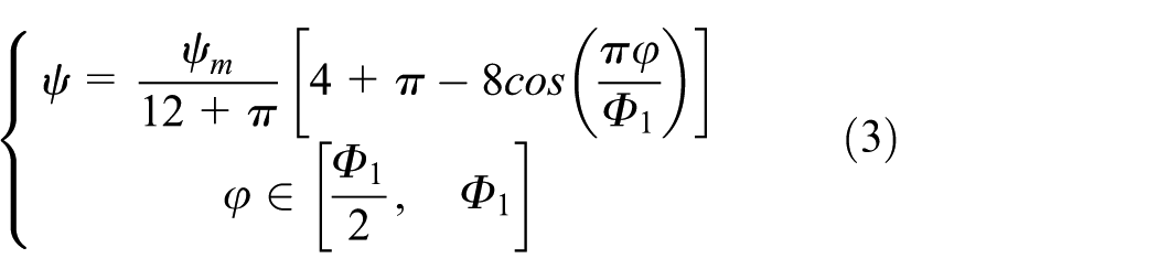
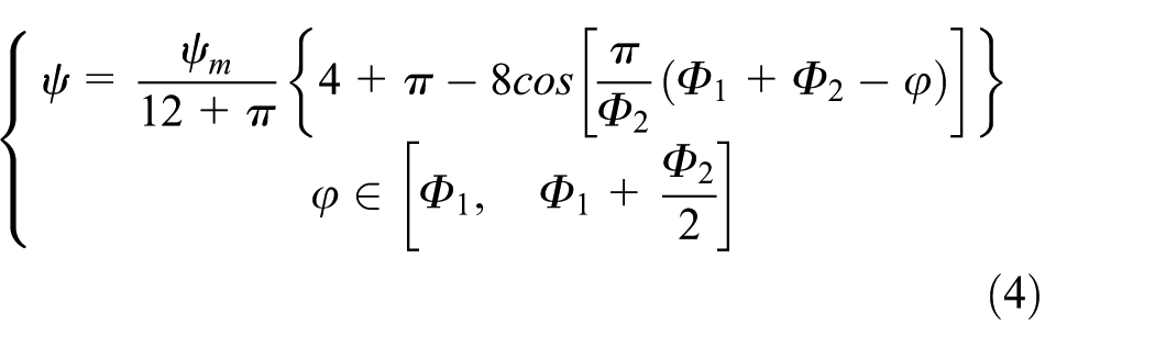
In the return period


In the inner dwell period,

Cartesian coordinates are established and shown in Figure 2, and the conjugate cam profile is deduced from equations (1) to (7). 10
Basic dimensions of the cam mechanism
The basic dimensions of the cam mechanism with roller follower include the follower roller radius r, the radii of the principal and deputy base circle Rb1, Rb2, respectively, the length of upper and lower followers LAB1, LAB2, respectively, and the center distance LAO. The radius of the base circle, the center distance, and the length of the follower have a significant effect on the cam profile and directly determine the motion performance of the mechanism. The pressure angle is used to characterize the working performance of the cam mechanism. To ensure excellent mechanical transfer performance of the conjugate cam mechanism, the pressure angle of the principal cam should be kept small during the return period based on the premise that the maximum pressure angle is reduced during the rise period.
Derivation of the maximum pressure angle
The relationship between the pressure angle and the basic dimensions of the cam mechanism is shown in Figure 2, where the maximum pressure angle of the cam mechanism is primarily influenced by the motion law of follower and the basic dimensions. After determining the motion of the follower, the pressure angle is constant regardless of the radius of the base circle, and the length of the follower and the center distance both increase or decrease with the same proportion coefficient. Therefore, the factors that affect the pressure angle depend only on the relative length between them. The proportion coefficients

where

where
For different relative lengths, the curves of the maximum pressure angle of the principal and deputy cam are shown in Figures 3 and 4, respectively.

Maximum pressure angle of the principal cam.
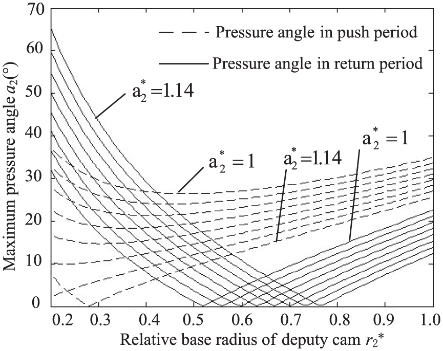
Maximum pressure angle of the deputy cam.
The curves of the principal cam’s maximum pressure angle versus relative base radius are shown for the rise and return periods by the solid and broken lines, respectively, in Figure 3. The curves from top to bottom in the rise period correspond to the curves from left to right the in return period, the ratios between the base radius of the principal cam and the lengths of the corresponding follower are represented on the horizontal ordinate, and the maximum pressure angle is represented on the ordinate. Each curve represents the equivalent line of the center distance and length of the corresponding follower which start from
By comparing Figures 3 and 4, it can be shown that the maximum pressure angle decreases with increasing
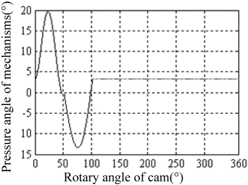
Relationship between the pressure angle and the rotary angle of the mechanism.
Dynamic modeling and analysis of mechanism with clearance
Clearance exists between the roller and the profile of the cam due to errors in manufacturing and installation of the geometry locking cam mechanism. The normal direction of the contact surface at the two contact points varies during the motion of the cam mechanism. This model belongs to the cam follower system of geometric locking, and the simplified dynamic model is shown in Figure 6.

Dynamics model of mechanism.
In Figure 6, yc is the induced vibration equivalent displacement of the working side, y is the output displacement of the working side, m is the equivalent quality of the model, k is the equivalent stiffness of the model, and c is the working damping coefficient. In this model, the kinematic pair gap composed of roller and cam profiles is assumed to describe the dynamic behavior of the kinematic pair mechanism.
The differential equation of motion of the cam follower mechanism is as follows

where δ is the distance between the follower roller center and the cam theory profile (mm), and α is the pressure angle of the cam mechanism (rad).
The theoretical output curve (engagement pair clearance δ = 0 mm) and prototype testing curve (engagement pair clearance δ = 5 mm) are compared in Figure 7. The curves in Figure 7 are generally continuous and smooth, and the slight distortion is produced by clearance, causing residual vibrations to persist during the rest stage. The change of speed is relatively stable, corresponding to the previous rule, and this transmission stability meets design requirements.
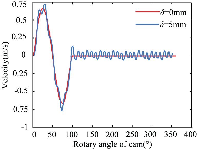
Dynamic velocity curve of the working part.
Results and discussion
The key components of the cam cutting mechanism with oscillating follower for PC steel bars include the cam, oscillating follower, spindle, and shaft. The performance of the component is directly related to the accuracy of the simulation results; thus, modeling the components accurately is crucial. The oscillating follower is one of the important parts in the cutting system, and its structure affects the work performance significantly. One end of the oscillating follower is designed with a cutter, and the cutting of the PC steel bars is realized through an up-and-down swinging motion. On the other end of the oscillating follower is two rollers, which are in contact with the outer contour of the two cams, thus realizing the oscillating traverse motion of the rotation axis. The transmitted force during the cutting process is large, and so ZG35 is chosen as the material of the follower to provide sufficient strength. The Herringbone institutions of the follower can realize its function with advantages of reasonable force and long working life. The integral assembly of the mechanism is shown in Figure 8.

Integral assembly of the cam mechanism.
The curves of the oscillating follower movement parameters in the cutting mechanism are shown in Figure 9. The maximum angular displacement of the oscillating follower is slightly larger than the theoretical value of 3.57° because of the inertial force. The upper roller continues to swing after separating from the profile of the cam at the ending point. Compared with the theoretical curve, the angular velocity only changes slightly. The clearance in the inner dwell part is approximately 0.45 mm, and concussion occurs in the acceleration curve because of this clearance. The mutation of the concussion is small during the course of the work; therefore, the stability of the cutting mechanism meets the design requirements.
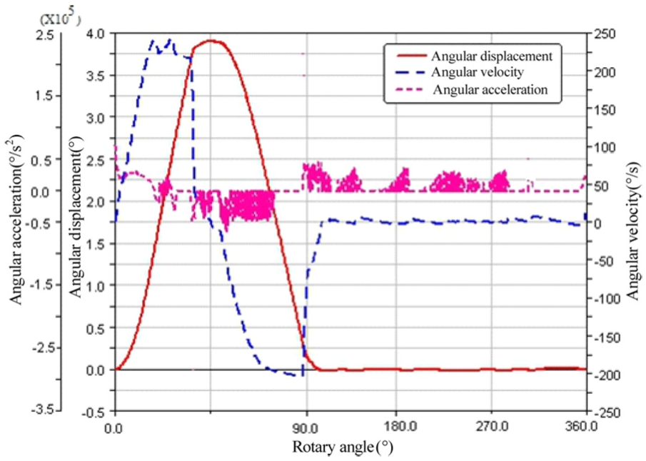
Curves of the follower movement parameters.
The change of main shaft torque is shown in Figure 10. The maximum torque to overcome is 2338 N m to finish cutting. Because of the change of clearance during the cutting process, the torque of main shaft is subject to a slight mutation at the end of the rise and return periods, but the variation range is very small, so the mechanism works normally. The main shaft torque is disturbed because of the clearance without an additional periodic force and torque. The horizontal vibration of the main shaft is avoided during normal operation, thereby ensuring normal operation of the cutting mechanism.

Torque curve of the main shaft.
The cam cutting mechanism with oscillating follower is designed based on the analysis results above. Online sizing cutting tests were carried out as shown in Figure 11. The diameter of the PC steel bar was ∅9–∅13 mm. The traction speed of steel bar was 70 m/min, and the error of the cutting length was less than or equal to ±1 mm; therefore, the overall performance of the mechanism reaches expected targets and meets technical requirements of production.

Cam cutting mechanism with oscillating follower.
Conclusion
According to requirements of the cam cutting mechanism in working condition, the action of the cutter is analyzed. A single-dwell-modified sine curve is chosen as the motion law of the oscillating follower. The relative proportion model between the radius of the base circle, the length of the follower, and the center distance is established. The design parameters of the conjugate cam mechanism are determined based on the relationship between the basic parameters of the cam mechanism and its pressure angle:
The cam cutting mechanism is designed based on the specific parameters above. Dynamic performance is studied by rigid body kinematics and mechanical system dynamics theory, thereby accounting for the existence of clearance.
Simulation and prototype experiments show that the motion performances of the cam cutting mechanism meet design requirements. The impact force between the cam and oscillating follower is small, and the stability of mechanism can be effectively guaranteed. The research results provide a basis for the design and application of this cutting device.
Footnotes
Handling Editor: Fakher Chaari
Declaration of conflicting interests
The author(s) declared no potential conflicts of interest with respect to the research, authorship, and/or publication of this article.
Funding
The author(s) disclosed receipt of the following financial support for the research, authorship, and/or publication of this article: This project is supported by the National Natural Science Foundation of China (Grant No. 51605416), the Colleges and Universities in Hebei Province Science and Technology Research Youth Fund (Grant No. QN2016095), and the Hebei Province Science Technology Research and Development Program (No. 12215604D).