
Abstract
In this article, an adaptive cruise control algorithm with braking energy recovery is proposed. First, the influence of the working characteristics of motor and battery on the energy recovery is analyzed in the braking energy recovery system. Considering the requirements of the braking regulations, the genetic algorithm is used to optimize the economy and safety during the braking energy recovery process. Braking force allocation strategy results can be obtained by offline lookup table. Based on the model predictive control theory with particle swarm optimization algorithm, an adaptive cruise control strategy is constructed to recover the braking energy as much as possible under the premise of satisfying vehicle tracking, safety, and comfort performance. Use Carsim as the simulation platform, and then co-simulate it with MATLAB/Simulink which is embedded with control algorithm. Simulation results show that distance error ratio and speed error ratio are mostly within 10%, braking energy recovery rate can up to 43.65% or more.The stability and comfort performance can also meet the control requirement.
Keywords
Introduction
In recent years, the rapid development of economic has resulted in the increase of car ownership. The growth rate of car has exceeded the growth rate of road resources, which led to serious traffic congestion problems. The adaptive cruise control system can realize the effective perception of surrounding environment of vehicle by relying on the accuracy and stability of the electronic control system.1–5 To avoid the possibility of rear-end accident and improve vehicle safety effectively, the safety distance should be kept by controlling the vehicle driving and braking system. During the tracking process, considering how to effectively recover the braking energy in the process of vehicle braking will significantly improve the economy of vehicle.6–9
For adaptive cruise control (ACC) controller design, various control algorithms such as proportional–integral–derivative (PID) control strategy, 10 fuzzy control algorithm, 10 sliding mode control algorithm, 11 and neural network learning algorithm 12 have been applied. Model predictive control (MPC) algorithm is widely used because it can predict the future state of ACC system. Analysis of the application of MPC in place of standard cruise control for passenger cars with the goal of maximizing fuel economy in urban traffic is given in Kamal et al. 13 and Koch-Groeber and Wang. 14 Bageshwar et al. designed mode-switching ACC using MPC, which shifted controllers between two modes, that is, speed control and distance control. The cost function was built using the distance error and relative speed, and the constraint was realized by limiting longitudinal acceleration. 15 Li et al. adopted MPC theory in ACC system. Fuel economy, tracking capability, and the driver desired response are considered in cost function. A constraint-softening method is employed to enlarge the feasible region. 16 An ACC controller was designed for a smart car. Eight different control methods, which are based on PI and MPC in different flavors, are proposed in Corona and De Schutter. 17
For regenerative braking system, Bera et al. 18 designed sliding mode controller to balance the braking force distribution between regenerative and antilock braking. Considering the desired yaw moment and road friction coefficient, a genetic algorithm (GA) is developed to increase recuperation energy while satisfying the vehicle stability. 19 The regenerative braking system integrated with fuzzy logic controller structure is presented and simulation results under ADVISOR environment are analyzed in Zhang et al. 20 A fuzzy-logic-based regenerative braking strategy considering braking stability and energy recuperation efficiency is developed. To ensure the braking stability, the braking force distribution is designed to accord with the ideal distribution curve. The vehicle states and battery states are taken into account for increasing energy recuperation efficiency. 21
It is rarely studied that the braking energy recovery technology is introduced into ACC system. This article will study on this technology. Optimized by GA, braking energy recovery technology takes vehicle safety, motor efficiency, battery efficiency into account. Taking the vehicle tracking, safety, comfort, economic performance indicators into account, ACC system will use MPC algorithm with particle swarm optimization (PSO) algorithm to control tracking ability.
Regenerative braking system
Vehicle platform
A single-shaft driven pure electric vehicle equipped with adaptive cruise control system and regenerative braking system is used in this article. The vehicle layout is shown in Figure 1.

The structure of pure electric vehicle.
The adaptive cruise control system obtains the surrounding environment information of the vehicle through radar or camera.22,23 By analyzing environmental information and vehicle information, the vehicle can safely follow the lead vehicle. 24
The regenerative braking system (RBS) is mainly composed of battery, motor, and hydraulic brake system with pedal stroke simulator. Motor and battery can work together to recover the braking energy during regenerative braking. Electronic stability program (ESP) hydraulic control unit which can generate high-pressure brake fluid with hydraulic pump is an important part of hydraulic brake system. 25
When driver steps on the brake pedal, adaptive cruise control system is off, the brake fluid from master cylinder can flow into pedal simulator to get the feedback of pedal feel which is similar to the traditional braking system. When driver turns on adaptive cruise control system, active pressurization control of ESP can realize the target deceleration without driver intervention.
The system is divided into three levels: Highest level, second level, and third level. The highest level contains vehicle controller and adaptive cruise control system controller, whose main task is to obtain vehicle state and control the host vehicle to follow the lead vehicle. The braking controller, battery controller, motor controller are put in the second level, which can coordinate regenerative and hydraulic braking torque. Driving and braking system without controller are included in the third level, whose task is to realize driving and braking process under the controller’s supervision.
Electric braking system
Battery model
Li-ion battery is chosen as the power source. As shown in Figure 2, the battery model is simplified as an internal resistance model, which was described in Li et al.
26
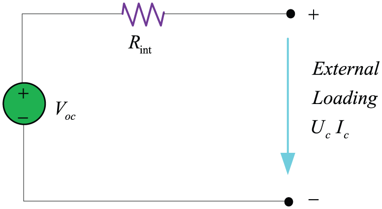
The internal resistance model of battery.
Motor model
The permanent magnet motor is selected in this article. The motor efficiency
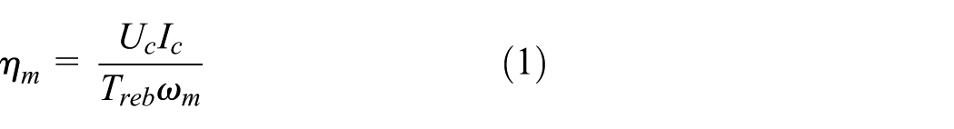
where
Motor efficiency is more sensitive to speed variation than to torque. The motor efficiency is highest in the vicinity of the base speed and relatively high in motor constant power region. When motor speed is lower than a certain value, motor efficiency is extremely low, so the motor braking torque should be reduced. 6
As depicted in Figure 3, the maximum regenerative braking torque

where

Motor regenerative braking region.
Regenerative braking control strategy
The braking force distribution is the key point of regenerative braking control strategy. The braking force distribution mainly consists of two parts:
Part 1: front and rear axle braking force distribution;
Part 2: hydraulic braking force and motor regenerative braking force distribution.
Part 1 mainly affects braking stability; Part 2 mainly affects vehicle braking energy recovery efficiency. The braking stability and braking energy recovery efficiency is a contradictory target which should be balanced.
Braking stability
In order to exert motor braking ability to gain braking energy as much as possible, more braking torque should be allocated on driving axle. Unreasonable braking force distribution of front and rear axle can cause the vehicle to lose stability. The best braking safety can get when front and rear wheels are locked at the same time. This situation can be expressed as

where
The ratio of front axle braking force to the total braking force is defined as braking force distribution coefficient

When front and rear wheels of vehicle are locked at the same time, combining formulas (3) and (4), the ideal braking force distribution coefficient
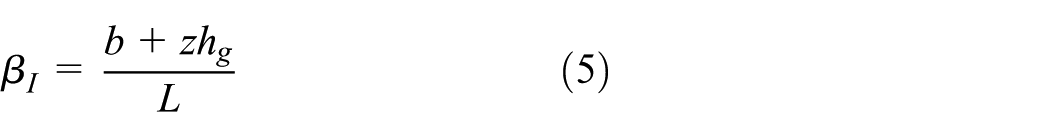
where
To make braking force distribution more reasonable,

Braking energy recovery efficiency
Electric motor can work as a generator during the regenerative braking procedure which can transfer mechanical energy from the wheels to an electrical load. The energy flow is generated by the electric motor and charged into the power battery. Therefore, braking energy recovery efficiency is related with motor power-generating efficiency and battery charging efficiency.
The motor power-generating efficiency is associated with motor speed and regenerative braking torque. Generating power of motor

The battery charging efficiency

Combining formulas (7) and (8), the effective power stored in battery during regenerative braking procedure can be expressed as

Considering the braking strength
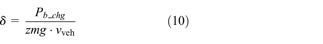
where
Application of GA for braking force distribution
Braking energy recovery efficiency and braking stability is a contradictory problem. To increase braking energy recovery efficiency, brake stability performance will be reduced. How to perform a delicate balance between the targets in competitive relationship is the key to solving the multi-objective optimization problems, which means seeking non-dominated solution set in the decision space.
GA has great superiority in solving global multi-objective optimization searching problems. It is not subject to the constrains of the problem and can effectively maintain population diversity and evenness.
Objective function
As stated,

where
Constraint conditions
Regenerative braking torque
Regenerative braking torque

where
Taking Economic Commission of Europe (ECE) regulations into account on the requirements of braking force distribution, the adhesion coefficient utilization
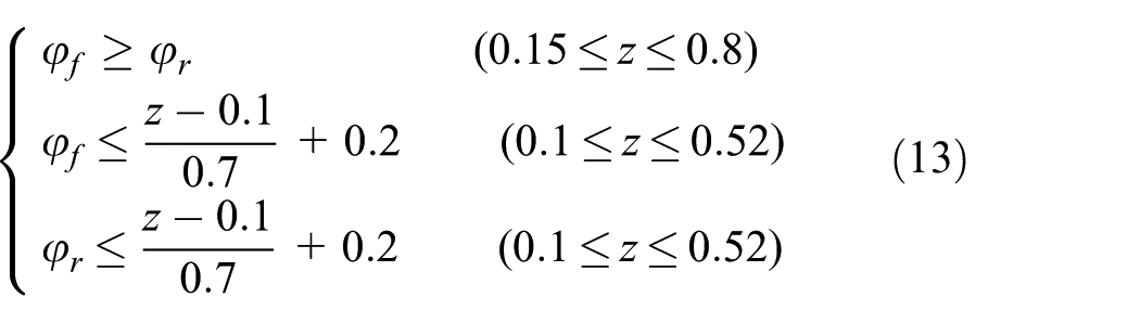
The definition of

Where,
Combining formulas (13) and (14), the limitation of

Simulation
As depicted in Figure 4, GA starts from a population of randomly generated individuals, which can be called a generation. In each generation, the fitness of every individual in the population is evaluated. The more fit individuals are modified to form a new generation. Commonly, the algorithm terminates when a maximum number of generations has been produced. Given that the objective function and the constraints are clear,when motor speed, SOC, braking strength are given,GA will calculate the optimal value of regenerative braking torque and braking force distribution coefficient. As shown in Figure 5, GA calculation results are made into a table which could be obtained offline.

The flowchart of GA.

Coordination control table of motor and battery.
Adaptive cruise control strategy
Adaptive cruise control systems are used to automatically maintain the speed of a vehicle at a desired speed set-point. It has been shown that fuel economy while in cruise control can be improved using advanced control methods. The objective of this article is to validate a model predictive controller implemented in a vehicle.
Based on MPC framework, 28 PSO is introduced into solving an open-loop optimization problem for the prediction horizon with constrains at each time step. 29 The concrete control process of adaptive cruise control system is shown in Figure 6.

The flowchart of ACC based on MPC.
The controller takes longitudinal dynamic model of host vehicle as the control object. Based on the movement sate of host vehicle and lead vehicle,with consideration of the tracking, safety, comfort and economic index during the vehicle follow-up process, MPC algorithm can predict the state of host vehicle in a finite time-horizon dynamically, and the particle swarm optimization algorithm is used to optimize the target acceleration. The first value of the optimization results is applied to control target acceleration of host vehicle.
Lead vehicle prediction model
The current control action of MPC optimization algorithm is obtained by solving the optimal control problem in a finite time domain

where
Safe intervehicle distance model
The safe intervehicle distance of adaptive cruise system is influenced by vehicle safety, road utilization, and driver acceptance. If the intervehicle distance is too small, driver will have insecurity and cause a collision accident. If the intervehicle distance is too large, the road utilization rate is low and other lane vehicles can insert. At present, the vast majority of car manufacturers adopt constant time headway as intervehicle distance algorithm, as shown

where
From formula (17) we can see, the faster the host vehicle is, the greater the safety distance can be. This trend is in line with the actual driving feeling.
Host vehicle predictive model
Through the establishment of predictive model, MPC can use the historical information of the research object to predict future information. When the predictive model is established, predictive model is required to be accurate and simple.
Because of the delay characteristics of vehicle driveline system, the input and output characteristics of vehicle longitudinal dynamic system can be described by the first-order inertia link

where a is the actual acceleration, u is the desired acceleration, K is the system gain, and T is the time constant
Combined with the longitudinal kinematic characteristics of vehicle, the vehicle prediction model of longitudinal motion is established as follows

Discretization of the established state equation by the zero-order preserving method
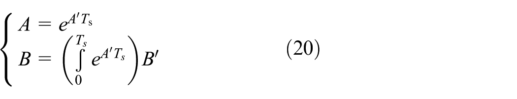
Therefore

where

Taking battery status changes into account during vehicle braking energy recovery process, formula (23) can be expressed

The Euler method is used to discretize formula (23)

where
Combining formulas (21) and (24), the discretization state of model can be obtained.
Performance index
The performance index is the quantified form of system control target. Therefore, the tracking, safety, comfort, and economic performance index of host vehicle are the design basis of system control target during the design of adaptive cruise control system. The system control goal is the synthesis of each performance index.
Tracking index
The adaptive cruise system needs to follow the lead vehicle stably, including speed follow and distance follow. In this article, velocity error and distance error are selected as tracking index, and then the tracking index of

where
Safety index
To avoid collision risk of two vehicles, the host vehicle should keep a safe intervehicle distance from the lead vehicle. At the same time, the speed error of vehicle tracking process should be limited to a reasonable range. Therefore, velocity error and distance error of

where
Comfort index
As an important function of active safety, ACC should ensure that the driver has a good driving feeling when it is turned on. An unreasonable longitudinal acceleration can make driver discomfort. The square of the longitudinal acceleration is used as the evaluation index of comfort that can be calculated as follows

where
Economic performance index
The economic performance index is mainly reflected by regenerative braking energy recovered in a finite time domain. According to the previous analysis, it is found that the recovery of braking energy is affected by the charging efficiency of battery and the power generation efficiency of motor under the premise of ensuring vehicle braking safety. At the sampling time of

Therefore, economic performance index can be expressed as

where
Application PSO for MPC
Based on current vehicle state and previous input variables, the PSO algorithm is adopted in MPC strategy to look for optimal control laws at every time step (Figure 7). The optimization process is divided into five steps as follows:
Step 1. To prevent PSO from reaching a local optimum, the initialized particles should be distributed in rational area averagely. Richard and Ventura proposed a population initialization method based on centroidal Voronoi tessellations (CVTs); 30 Campana et al. 31 rewrote the standard PSO iterative formula into a linear dynamic system, based on which they research the initial position of particle swarm, making them have orthogonal trajectories.
Step 2. By introducing the braking energy recovery technology into the ACC system, state variables
Step 3. Combined with the quantized values of tracking, safety, comfort, and economic performance index, cost function is designed as

Based on the cost function of every combination, the global and individual optimal particles in its history can be selected.
Step 4. Judge whether the ending condition is satisfied. If it is, the first step of optimal control sequence should be output. If not, in order to optimize the performance of every particles, every particles should update their velocity and position with consideration of the best position of its history state and global state.
Speed update formula of particle i of d dimension is given by

Location update formula of particle i of d dimension is given by

where t is number of iterations; w is the inertia weight, adjusting the search space for the solution space;
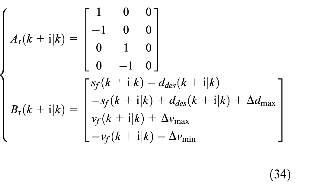
Step 5. According to the performance requirements of the vehicle, the state variables and control variable are constrained to meet the following requirements
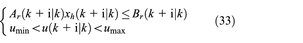
where

Application PSO for MPC.
Judging whether or not the updated particle satisfies the constraint condition. If the constraint condition is satisfied, the process proceeds to Step 2. If the constraint condition is not satisfied, the particle value is modified by the constraint condition, and then the process proceeds to Step 2.
Simulation results and analysis
The control strategy proposed in this article is compared with the regenerative braking control strategy using the fixed braking force distribution coefficient by simulation. The simulation platform is built as follows: Carsim is used as the vehicle simulation platform, and the control algorithm is designed on MATLAB/Simulink. Through joint simulation, the simulation results can be analyzed.
Basic parameters of host vehicle are shown in Table 1. The driving cycle of lead vehicle is shown in Figure 8. Lead vehicle is starting at 30 m from the starting point and the vehicle speed is between 20 and 60 km/h. Three different braking strengths (0.1, 0.2, and 0.3) are used to test the vehicle’s tracking performance and energy recovery performance.
Basic parameters of host vehicle.


Driving cycle.
The simulation results of distance and speed tracking performances are shown in Figures (9)–(12).

Distance tracking.

Distance error.

Speed tracking.

Speed error.
In order to facilitate data analysis, the distance error ratio and speed error ratio are defined. These are respectively shown in formulas (35) and (36)

For the distance error ratio, as shown in Figures 9 and 10, 90% of distance error rate can be mostly maintained within 10%. Influenced by the initial valve of simulation, the large distance error ratio which exceeds 20% accounts for a smaller proportion. In general, the distance tracking performance can meet driving needs.
During the tracking process, speed error ratio is more sensible than distance error ratio, as shown in Figures 11 and 12; 81% of speed error rate can be maintained within 10%. Less than 1% of speed error rate which exceeds 30% often occurs in some extreme cases. The initial simulation parameter and a large braking strength which is suddenly forced on lead vehicle can lead to extreme cases. The simulation results of recuperation energy are shown in Figures 13 and 14.

SOC state.

Battery power change.
With the braking energy recovery function of vehicle, as shown in Figure 13, the recuperation energy can be used to increase battery SOC during the braking process. In order to quantify the braking energy recovery effect, the braking energy recovery rate is defined

where
Through the analysis of Figure 14, the braking energy recovery rate under three different braking strengths is calculated in Table 2.
Braking energy recovery performance.

The distribution relationship of front and rear braking force influences the braking stability, and the braking stability can be higher if the curve on behalf of the distribution relationship gets closer to curve I. As shown in Figure 15, the front axle braking force accounts for a large proportion during small braking strengths. With the increase of the braking strength, the proportion of the rear axle braking force is gradually increased. The braking stability can be calculated by the ratio of the average braking force distribution coefficient and the ideal braking force distribution coefficient, and the results are shown in Table 3.

Front and rear axle braking force distribution.
Braking stability performance.

The comfort performance can be obtained by the acceleration analysis. As shown in Figure 16, the acceleration does not show a drastic change during the driving and the braking process. Acceleration is controlled within 1.5 m/s2 during the driving process, and deceleration is controlled within 4 m/s2 during the braking process. With a satisfied driving comfort, the host vehicle can follow the lead vehicle.

Acceleration change.
Conclusion
This article introduces the braking energy recovery function into ACC system. According to the influence of braking energy recovery and braking safety, the regenerative braking torque and the braking force distribution coefficient are optimized by GA. For the ACC system, with consideration of the tracking, safety, comfort and economic index, based on MPC, control algorithm builds up a theoretical platform and uses the PSO algorithm to optimize the target acceleration. Simulation test is carried out under different braking strengths with the joint simulation of Carsim and MATLAB/Simulink. The results show that distance error ratio and the speed error ratio are mostly within 10%; braking energy recovery rate can up to 43.65% or more. The vehicle stability can be improved as the braking strength increases and acceleration is limited to a reasonable range during the driving and the braking process. At the same time, the proposed control strategy is compared with the regenerative braking control strategy using the fixed braking force distribution coefficient. Compared with the contrast control strategy, the proposed control strategy has a higher braking energy recovery ability. The vehicle stability under the control strategy proposed in this article will be closer to the contrast control strategy as the braking strength increases
Footnotes
Handling Editor: Seung-Bok Choi
Declaration of conflicting interests
The author(s) declared no potential conflicts of interest with respect to the research, authorship, and/or publication of this article.
Funding
The author(s) received no financial support for the research, authorship, and/or publication of this article.