
Abstract
Functionally graded material is a new class of composite materials with gradually varying material contents. In this article, a two-dimensional axisymmetric time-domain spectral finite element method is proposed for the analysis of elastic wave propagation in functionally graded cylinders. The stiffness and mass matrix of an arbitrary quadrilateral axisymmetric spectral element is developed. The element nodes are collocated at Gauss–Lobatto–Legendre points. High-order Lagrangian polynomials are used as shape functions and the Gauss–Lobatto–Legendre quadrature rules are applied. They provide the capability to model spatial varying material properties and lead to a diagonal mass matrix. The effectiveness of the proposed model is verified by comparing with published data. Elastic wave propagation in a functionally graded cylinder subjected to an impulsive loading is studied detailed. The effect of material grading pattern is analyzed. The results demonstrate the effectiveness of the present method for the analysis of elastic wave propagation in functionally graded solids with axial symmetry and the material composition variation has an important effect on structural wave propagation behavior.
Keywords
Introduction
Functionally graded material (FGM) is a new kind of composite materials with gradually varying material properties tailored to specific applications. Compared with the common layered composite material, one of the superior properties of FGM is that the continuous gradation in material content can overcome the interfacial problem arisen from sudden change in material properties at the interfaces of different phases. 1 FGMs have been increasingly used in aerospace, nuclear, automotive and defense industries. In many of these applications, FGM structures usually serve as critical parts in the whole assemble. However, on the other hand, these FGM structures are often subjected to extreme loadings and prone to becoming damaged. To effectively detect damages in FGM structures which is critical to enable system reliability and safety, many damage detection methods have been proposed in recent years, such as vibration-based methods, and ultrasonic-based methods. Among these current methods, the guided wave damage detection method has attracted much attention due to its capability for online and long range interrogation of the structures. This method is based on the active or passive elastic wave stress propagation in the structures. To better implement the method, it is important to analyze and understand the wave propagation phenomenon in various structures. Therefore, the analysis of wave propagation in FGM structures is issued in this article.
A number of analytical studies have been carried out to study elastic wave propagation in functionally graded (FG) structures.2–7 An infinite FG plate subjected to a point impact was studied by Sun and Luo. 2 High-order shear deformation plate theory (HSDT) and Hamilton principle were used to obtain approximate analytical solutions in their work. Dispersion and power flow solutions for a FGM plate were given using the extension of Legendre polynomial approach by Lefebvre et al. 3 Lamb wave propagation in a FGM plate was studied based on the power series technique by Cao et al. 4 A semi-analytical method, which combines the state space method and the one-dimensional (1D) differential quadrature method, was developed to obtain the dynamic responses of FG circular plates by Nie and Zhong 5 A simplified 1D model is proposed to develop insight into the stress wave propagation in FGMs by Bruck 6 The free and forced vibrations of a FGM annular sector plate with simply supported radial edges and arbitrary circular edges were analyzed by Nie and Zhong 7 Although these analytical works can give some insight into the elastic wave propagation in FGM structures, they are limited to very simple boundary and loading conditions.
In recent years, many works on the analysis of wave propagation in complex FG structures by the conventional finite element method have been reported.8–11 For example, a beam element based on first-order shear deformation theory was proposed to study wave propagation behaviors of FGMs by Chakraborty et al. 8 The analysis of a FG hollow cylinder under dynamic impact was carried out in Shakeri and colleagues,9,10 where the FG cylinder was assumed to be made of many sub-cylinders. Each sub-cylinder was considered as an isotropic layer and the material properties in each layer were either constant 9 or assumed to vary linearly in the thickness direction. 10 Thus, FGM properties were resulted by suitable arrangement of layers in multilayer cylinder. The axisymmetric finite element model was applied to study the wave propagation in a thick hollow cylinder with finite length made of two-dimensional (2D) FGM subjected to impact internal pressure by Asgari et al. 11 Although it is validated that the conventional finite element method (FEM) has the ability to simulate the elastic wave propagation in FGM structures with arbitrary geometry and boundary conditions, the computational cost is often very high. The reason is that at high frequency, extremely precise finite element discretization in time and space domain is required to yield a converged dynamics solution. Hence, alternatives to the conventional FEM have been considered.
Recently, the time-domain spectral finite element method (SFEM), which was first proposed by Patera 12 in fluid dynamics, has been extended to analyze the problems of structural wave propagation.13–19 This method can be viewed as a special type of finite element methods and bears some similarity with the p-version FEM. The key idea of time-domain SFEM is the adoption of specific high-order shape functions. Local element nodes are distributed non-uniformly at the Gauss–Lobatto–Legendre (GLL) points. The Lagrangian interpolation polynomials pass through the GLL points. The GLL quadrature rules are applied to deduce element mass and stiffness matrices. As a result, high interpolation accuracy is achieved. Besides, the element mass matrix is diagonal due to the orthogonality of approximation functions. Hence, the time-domain SFEM is more effective compared to the conventional FEM for wave propagation problems. It is also noted that using high-order shape functions in SFEM can give better approximation of gradually varying material properties. Therefore, the time-domain SFEM is particularly suitable for the wave propagation analysis of complex FGM structures. However, the related works are few except that in Hedayatrasa et al., 20 a 2D plane strain time-domain SFEM was proposed to analyze the lamb wave propagation in FGMs. In addition, it is noted that beside the above time-domain spectral element methods, the transformed-domain SFEM methods have also been proposed to effectively solve the problems of elastic wave propagation.21,22
The main objective of this article is studying the elastic wave propagation in functionally grade cylinders by an efficient time-domain SFEM. An axisymmetric solid time-domain spectral finite element model is developed. The proposed SFEM, which combines the geometrical flexibility of the conventional FEM and the rapid convergence of spectral method, is capable to accurately analyze axial and radial oscillations with high-order approximation functions. This article is organized as follows. In section “Theoretical background,” the related theoretical background is introduced. In section “Spectral finite element modeling,” the axisymmetric solid spectral finite element formulations for the wave propagation in FG cylinders are deduced. The main purpose of section “Model validation” is to validate the proposed method by comparing with published data. In section “Numerical example and discussions,” elastic wave propagation in a FGM cylinder is studied in detail. In the last section, the conclusions are addressed.
Theoretical background
Basic equations
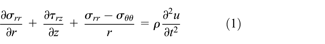
Consider a FG cylinder as shown in Figure 1. A cylindrical coordinate system (r, θ, and z) is applied to describe the cylinder geometry and deformation. The thickness of the cylinder is L and the radius is R. The cylinder is made of 1D FGM. The geometry of the cylinder and the loading considered here are not the functions of circumferential coordinate θ. It is known that there are an infinite number of guided wave modes in a cylindrical waveguide. Torsional waves can also be created under axisymmetric conditions. In this article, however, only axisymmetric wave modes are considered. In this case, the deformation becomes symmetrical with respect to the z-axis and the wave propagation problem can be considered as a plane axisymmetric problem. Thus, by neglecting the body force, the equilibrium differential equations written in 2D cylindrical coordinate (r, z) are 23
and

where t is time;

where

where the coefficients of elasticity is

In equation (5), E is Young’s modulus and

Geometry of a functionally graded cylinder.
Material properties
The cylinder is made of a combined ceramic–metal material and the material composition is graded continuously along either its thickness direction (z-direction) or its radial direction (r-direction). Let Vm and Vc denote the volume fraction of the metal phase and the ceramic phase, respectively. According to the homogenization scheme in Reddy and Chin, 24 Vm and Vc are related as

For the case of the cylinder’s material is graded through the z-direction, it is assumed that the top surface of the cylinder is pure ceramic and the bottom surface is pure metal. The variation of the volume faction of the ceramic can be defined by the well-known power law

where z denotes the z-coordinate of the cylinder and n is a non-negative constant. Using the classical rule of mixture, the distribution of the material properties can be expressed as

where P is the material properties such as Young’s modulus, Poisson’s ratio, and the mass density
Equation (8) indicates that at the top surface boundary (z = L) of the cylinder, a typical material property takes on the value P = Pc. Similarly, at the bottom surface boundary (z = 0) of the cylinder, a typical material property takes on the value P = Pm. Figure 2 shows the influence of power law index n on volume fraction. It is noted that in the case of n = 1, the material property is linear variation along the thickness direction.

The influence of compositional gradient exponents on volume fraction variation.
For the case of the cylinder’s material is graded through the r-direction, the grading pattern can be modeled similarly as equation (8), in which the variable z is substituted by variable r and the thickness L is substituted by the cylinder’s radius, R.
Spectral finite element modeling
Due to axisymmetry, the FG cylinder is approximated by finite elements in the plane of revolution (r-z plane). A 2D arbitrary quadrilateral spectral element is proposed to mesh the structure. The element is based on the high-order Lagrange polynomial interpolation. Figure 3 shows a typical 2D spectral element of fourth order in local and global coordinate system. It is noted that unlike the conventional finite element, the nodes of the spectral element are non-uniformly spaced. It is very important to avoid Runge’s phenomenon, which refers to a problem of oscillation near the edges of an interval that occurs when using polynomial interpolation with polynomials of high degree over a set of nodes spaced in a uniform grid. 25 For the proposed spectral element, the local nodes are located at the GLL points, which are the roots of the following equations

where

Typical 2D spectral element of fourth order in local (a) and global (b) coordinate system.
The interpolation of the displacement component u in the local coordinates

where

where k = 1,…, m; i, j = 1,…, n + 1. Therefore, the element displacement field can be written in the form of matrix as

with
Substituting equation (12) in equation (3), the element strain matrix can be obtained and defined as

where

The element stress matrix can be deduced by combining equations (4) and (13)

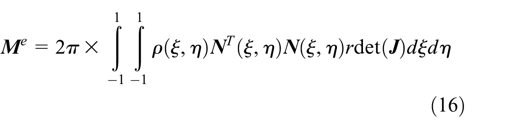
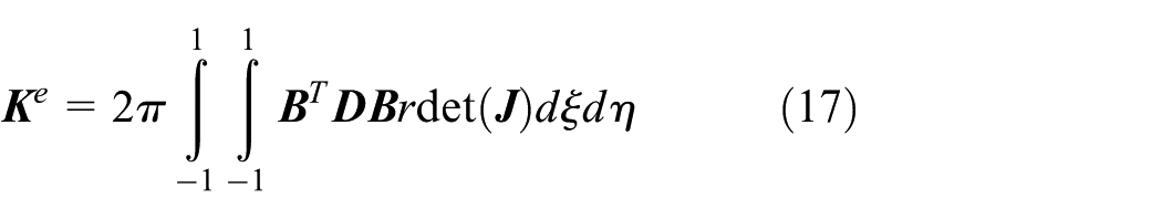
The resulted element mass and stiffness matrix
where
The element matrices


where
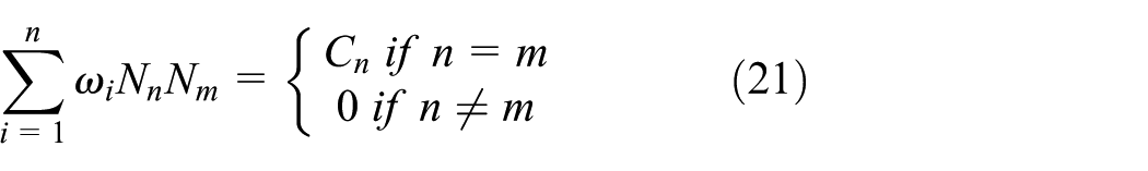
This significant orthogonality can result in a diagonal mass matrix when implementing the GLL integration. It is also noted that using GLL integration can decrease the complexity and improve the computation efficiency, but this integration scheme will typically result in “under-integration,” which may underestimate values of computed eigenfrequencies of the analyzed systems, when compared with other more accurate integration scheme like the Gauss integration.
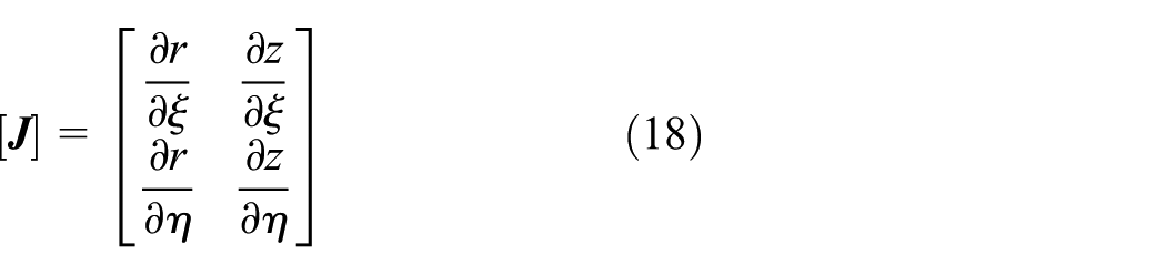
It is noted that the radial distance r in matrix
It can be found from equation (14) that when r becomes very small, the matrix
For the stiffness matrix calculation, the singularity can be eliminated by imposing exact boundary conditions. In plane axisymmetric problem, the ideal boundary conditions can be expressed as

The boundary condition is introduced to the stiffness matrix during calculation. The rows and columns of stiffness matrix corresponding to the r = 0 boundary degrees of freedoms are imposed as zero value, except for elements on the diagonal of the matrix, which should be fixed as one. 13 By this means, the effect of r = 0 are removed and the singularity of stiffness matrix can be solved.
For the mass matrix calculation, according to equation (16), the elements of mass matrix relative to r = 0 are zeros. For example, an element whose left boundary coincides with the symmetry axis is shown in Figure 4. The elements of this element mass matrix which are related to the green integration points are zeros. This will bring singularity when using the mass matrix for the process of direct numerical integration. In this article, an average mass distribution method is proposed. As shown in Figure 4, consider the blue integration points near the green integration points. The half of the mass concentrated at the blue points is given to the green integration points. Thus, the mass at the green points are not zeros. This method can eliminate zero elements in the main diagonal elements of mass matrix.
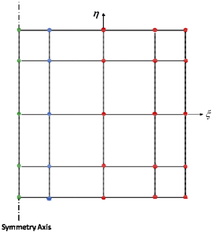
The illustration of the element mass distribution method.
Now by assembling the element matrixes, the global dynamic equilibrium equations for the FG cylinder can be obtained as

where the matrix

where

where
Model validation
This section is to validate the proposed axisymmetric time-domain spectral element model. Transient response in a FGM cylinder calculated by the conventional finite element method by Hosseini et al.
10
is used as a model problem. As shown in Figure 5, a thick hollow cylinder with material gradually changed along the radial direction is subjected to dynamic inner pressure. The inner radius of the cylinder is

The functionally graded hollow cylinder subjected to inner pressure.
It can be seen from equation (26) that the pressure increases until t = 0.005 s and transient wave propagation will occur after the end of the loading. In this example, the inner and outer wall of the cylinder is pure ceramic and pure metal, respectively. The properties of each material used in the FGM cylinder are listed in Table 1.
Material properties of ceramic and metal phase.

In Hosseini et al., 10 the FGM cylinder is assumed to be made of many sub-cylinders. Each sub-cylinder is considered as an isotropic layer. The material properties within a layer vary linearly in the layer thickness direction. The FGM cylinder is assumed to be in plane strain condition and is subjected to axisymmetric dynamic loading. Therefore, only 1D wave responses were solved by the conventional finite element method.
The time history and the frequency spectrum of the excitation loading are given in Figure 6. It can be seen that the excitation load has a frequency content of around 3 kHz. This frequency content is low. Generally, for the finite element method, about 20 elements are required per wavelength of the highest effective.25,26 In this validation example, the highest effective frequency results in the maximum element size of about 0.080 m. In this article, the cylinder is meshed by the proposed spectral finite elements with

The time history (a) and the frequency spectrum (b) of the excitation loading.
Figure 7 shows the comparison of the time histories of the radial displacement component at the middle of the thickness for n = 0.5 obtained by the present method with those published data in Hosseini et al. 10 A very good agreement is observed. This validates the effectiveness of the proposed spectral element method. The differences between the current results with those published in Hosseini et al. 10 are mainly from the 2D axisymmetric analysis is performed in this paper, while only 1D wave propagation equation was solved in Hosseini et al. 10 The effect of the Poisson ratio can be considered by the proposed method. Besides, the present high-order spectral element can give better approximation of the varying material properties than low-order linear finite element. Therefore, it is believed that the proposed axisymmetric time-domain spectral element model can give better results for the analysis of elastic wave propagation in FG cylinders.

The comparison of the time histories of the radial displacement at the middle point.
Numerical example and discussions
Model description
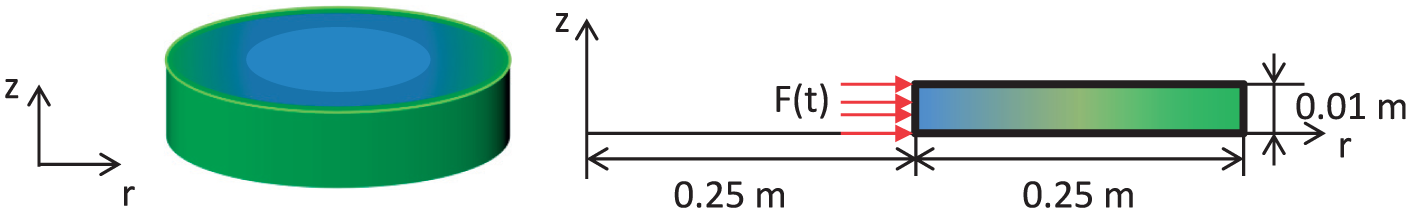
As shown in Figure 8, a FG cylinder with thickness L = 0.05 m and the radius r = 0.036 m is considered. Its top surface is pure ceramic (Al2O3) and the bottom is pure metal (Ni). The properties of two material phases are listed in Table 2.

Functionally graded cylinder under the axial impact.
Material properties of top and bottom surfaces.

To study the elastic wave propagation in the FGM cylinder, an impulsive loading is applied to the region with radius

where
To investigate wave propagation in the FG cylinder with a reasonable accuracy and computational cost, convergence study was carried out. It was observed that using sixth-order spectral element and meshing the structure with 6 elements in the radial direction and 16 elements in the axial direction can give results with a reasonable accuracy and acceptable time and source costs. The time step of integration is chosen as
As shown in Figure 9, three evaluation points are chosen to output displacement and stress time-history results. Point K is close to the loading area and near the ceramic surface (z = 0.05 m). Point L is located at the middle of the cylinder, and Point M is near the metal surface (z = 0 m).

The coordinates of the chosen observation points and boundary points.
Results and discussions
Figures 10 and 11 show the distribution of the axial displacement component

Distribution of the axial displacement component

Distribution of the radial displacement u(r, z) (m): (a) t = 5 µs, (b) t = 7.5 µs, and (c) t = 10 µs.
In Figure 10(a), the distributions of the axial displacement component
Figure 11(a) shows the distribution of the radial displacement component u(r, z) for n = 0.1, n = 1, and n = 10 at
The distributions of the radial stress component

Distribution of the radial stress
Figure 13 shows the distributions of the axial stress component

Distribution of the axial stress
Figure 14 shows the distributions of the shear stress component

Distribution of the shear stress
Figure 15 shows the distributions of the hoop stress component

Distribution of the hoop stress
The time histories of the radial u and axial w displacement components at the evaluation points K, L, and M are illustrated in Figures 16 and 17. The time history of the radial displacement at point K is plotted in Figure 16(a). After the loading is applied, the wave reaches to the point K at about
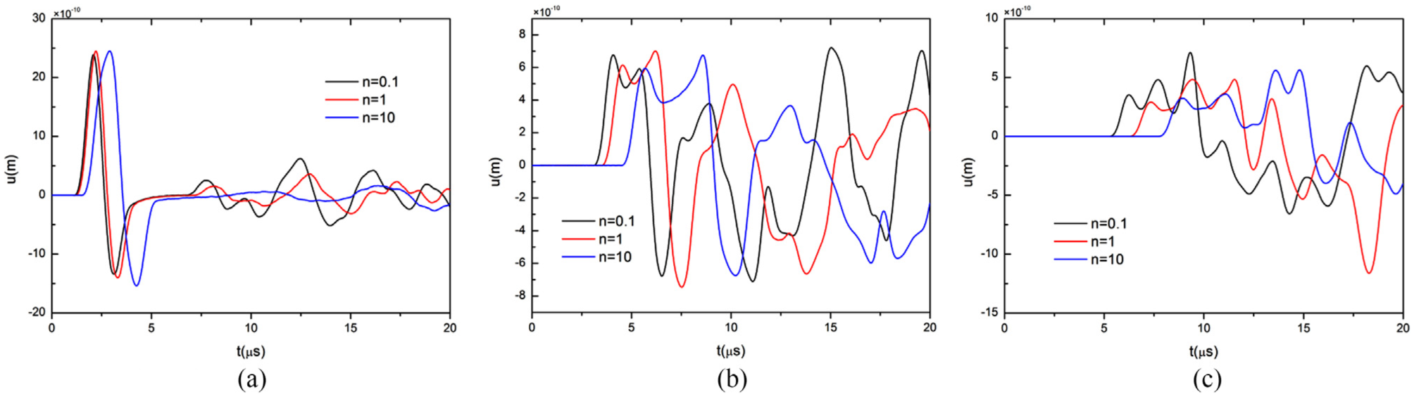
Time histories of the radial displacement at points K, L, and M: (a) K(0.006,0.04), (b) L(0.018,0.025), and (c) M(0.03,0.01).

Time histories of the axial displacement at points K, L, and M: (a) K(0.006,0.04), (b) L(0.018,0.025), and (c) M(0.03,0.01).
The time histories of

Time histories of the stress components at point K.

Time histories of the stress components at point L.

Time histories of the stress components at point M.
Conclusion
The axisymmetric solid time-domain spectral element method is proposed to study the elastic wave propagation in FG cylinders. The cylinder’s material is graded either in the radial direction or in the thickness direction. The time-domain SFEM based on the high-order interpolation functions and the GLL node collocation and integration is attractive because it can avoid Runge’s phenomenon and needs lower computational costs compared to the conventional finite element method. In addition, using high-order interpolation function can give better approximation of gradually varying material properties. The validation of the proposed method is carried out by comparing with published data.
A FG cylinder with material graded in the thickness direction subjected to an impulsive shock loading is studied detailed by the present method. The displacement and stress distributions and the time histories of displacement and stress components are obtained for various grading patterns. The results show that the compositional gradient exponent n does not have a distinct effect on the displacement or stress profiles but has an obvious influence on the wave traveling speed as well as the displacement and stress levels. The proposed method can be used to other types of axisymmetric FG structures like thick truncated cones and hollow cylinders, and also various loading and boundary conditions can be considered to these problems.
Footnotes
Handling Editor: Luís Godinho
Declaration of conflicting interests
The author(s) declared no potential conflicts of interest with respect to the research, authorship, and/or publication of this article.
Funding
The author(s) disclosed receipt of the following financial support for the research, authorship, and/or publication of this article: The present work was partially supported by National Science Foundation of China (no. 11372246).