
Abstract
A generalized finite element dynamic model of helical gear system considering time-varying mesh stiffness and loaded composite mesh error is developed. Bias modification is introduced into this model, and the corresponding time-varying mesh stiffness and loaded composite mesh error are determined based on improved loaded tooth contact analysis model. By introducing vibration exciting force, the time-variant differential equations of the system are transformed into time-invariant differential equations which can be solved faster by Fourier series method. Meanwhile, the internal excitation of the system can be captured clearly. Aiming to reduce vibration of the system, optimization method of bias modification is proposed with the objective of minimizing fluctuation of the vibration exciting force. The global optimal modification parameters are obtained using brute force optimization method. The sensitivity of dynamic response of the modified helical gear system to gear misalignment is then investigated. Simulation results suggest that bias modification has little effect on time-varying mesh stiffness but reduces system vibration significantly. Increasing gear misalignment will decrease time-varying mesh stiffness and increase the system vibration. Bias modification shows a well robustness in reducing vibration of helical gear system when gear misalignment is not too large.
Keywords
Introduction
Due to higher contact ratio, larger load carrying capacity, lower vibration, and noise, helical gear transmission systems are widely used in many industry applications, such as automotive, wind turbine, mining, marine, and industrial power transmissions. With the increasingly tight restrictions on the vibration and noise of gear systems, the prediction and control of gear vibration and noise are a crucial issue in the design of the gear systems. It is well known that gear modification is an advanced technology in reducing vibration and noise of gear transmission. To obtain reasonable modification parameters for the gear design and processing is of great importance.
Since the profile modification method was proposed by H Walker 1 for involute gear pair at first in 1938, numerous researches focused on the profile modification for spur gear system. Some of research works were related to the quasi-static contact analysis of spur gear system with profile modification,2,3 aiming at minimizing the amplitude of static transmission error,4,5 while others were devoted to investigate the effect of profile modification on dynamic behaviors of spur gear system,6–11 aiming at minimizing the dynamic response of the system. 12 Meanwhile, some of published literature focused on tooth surface modification for reduction of vibration and noise of helical gear system. Unlike spur gears, the calculation of mesh stiffness and load distribution are a complicated three-dimensional contact problem for a helical gear pair under load because the applied loads are not evenly distributed along the line of contact. Conry and Seireg13,14 proposed a universal contact model of two elastic bodies based on compliance analysis method to the calculation of load distribution and elastic deflection of gear tooth and developed gear modification method for spur and helical gear. Simon 15 presented a method for the calculation of optimal tooth modifications for spur and helical gears aimed at minimizing load distribution factor. Umeyama et al. 16 developed a transmission error calculation model for cylindrical gear based on the finite element method and Hertzian contact analytical formula and studied the influences of gear-dimensional parameters and tooth surface modification on the transmission error. Rao and Yoon 17 presented a method of computing the three-dimensional variation in transmission error of helical gears on the basis of the analysis of the plane of action generated by a pair of mating teeth and used cubic splines to determine the optimal helical tooth profile. Wang and Zhang 18 proposed an analytical model for calculating time-varying mesh stiffness of helical gears with tooth profile error based on potential energy method and thin slice theory and analyzed the effects of tooth errors and gear modification on the loaded tooth contact characteristics of helical gears. Bruyère and colleagues19,20 proposed a perturbation method to obtain approximate closed-form expressions for profile relief that minimize the amplitude of quasi-static transmission error under load and presented two original analytical formulations which give the amount and length of profile modifications minimizing the amplitude of quasi-static transmission error in narrow-faced spur and helical gears. Maatar and Velex 21 investigated the effects of profile modification and lead modification on static transmission error, load distribution, and dynamic transmission error of narrow-faced helical gears. Wu et al. 22 established a static contact finite element model of helical gear pair in ANSYS software to provide a profile modification scheme based on elastic deformation of gear teeth along the line of action and used dynamic contact finite element model to investigate the effect of profile modification on dynamic responses of the system.
In addition, some current researches are devoted to study robust optimization method for gear modification design of cylindrical gears. Park 23 proposed a method to determine optimal lead curve and robust tooth surface design, using the response surface method and multi-objective optimization. Ghribi et al. 24 combined analytical results and numerical simulations to design a robust profile modification to spur and helical gears. Artoni et al. 25 proposed optimization method of tooth surface modification for cylindrical gear to achieve low sensitive of loaded static transmission error to applied torque and misalignment.
With published literature mentioned above, numerous researches have been carried out to investigate the effect of profile modification and lead modification on the quasi-static and dynamic characteristics for spur and helical gear system. However, as an effective method to reduce vibration and noise for helical gear system, bias modification has not been studied a lot at present, especially the loaded tooth contact characteristics of helical gear pair with bias modification and the effect of bias modification on reduction of vibration and noise of helical gear system have not been analyzed in detail. Meanwhile, the current researches lack the comprehensive and thorough investigation of the effects of gear misalignment on loaded tooth contact characteristics and dynamic behaviors of helical gear system with bias modification.
The main motivation of this study is to investigate the effect of bias modification on loaded tooth contact characteristics of helical gears, obtain the optimal bias modification parameters quickly, and analyze the sensitivity of dynamic responses of helical gear system with bias modification to gear misalignment based on a more precise generalized finite element dynamic model of the system. After this introduction, the rest of this article is organized as follows: section “Bias modification and dynamic model” gives the design of bias modification for helical gears and the calculation method of corresponding time-varying mesh stiffness and loaded composite mesh error based on the improved loaded tooth contact analysis (LTCA) model. Section “Vibration exciting force” develops a more precise generalized finite element dynamic model of helical gear system based on the finite element method and Timoshenko beam theory in order to consider shaft deflection, bearing location, and the direction of power flow. By introducing vibration exciting force, the time-variant motion differential equations of system are transformed into time-invariant equations and the dynamic responses can be obtained faster by Fourier series method. Section “Numerical results and discussion” gives a comparison of solution method in order to validate the proposed approximate transformation in section “Vibration exciting force.” Aiming to minimize the fluctuation of vibration exciting force, the optimal bias modification parameters are obtained by global brute force optimization method in potential ranges, and the effects of gear misalignment on dynamic responses of helical gear system with bias modification are investigated. Section “Conclusion” draws the main conclusions of the numerical simulation results of helical gear system with bias modification. The detailed simulation flowchart is shown in Figure 1.

Flowchart of the simulation.
Bias modification and dynamic model
Description of bias modification for helical gear
As removing material from the bias of gear tooth along the contact line, bias modification consists of three basic parameters: the modification curve, the amount of modification, and the length of modification. Schematic diagram of bias modification of helical gears on tooth surface and plane of action are displayed in Figure 2, where the shaded region is the bias modification region, and B1B2B3B4 is the plane of action. The X1OY1 is the Cartesian coordinate system to define the plane of action, and O-X2Y2Z2 is the Cartesian coordinate system for calculation. L is the normal length of bias modification, and La is the maximum potential length of bias modification. In this section, the symmetric bias modification on plane of action is adopted because tip modification of the pinion is equivalent to root modification of the wheel.
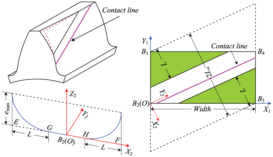
Schematic diagram of bias modification for helical gears.
The equation of bias modification curve in the X2OZ2 coordinate system can be written as

where ei is the modification amount of potential contact point i; xi is the coordinate of contact point i along X2-axis in the O-X2Y2Z2 coordinate system; emax is the maximum modification amount; n = 1 denotes that the modification curve is a straight line; and n = 2 denotes that the modification curve is a parabola curve, respectively. Parabola curve is adopted for bias modification in this article.
Mesh stiffness and loaded composite mesh error
The dynamic engagement process of a gear pair can be regarded as the quasi-static loaded contact process of two elastic bodies, as shown in Figure 3. When the external force P is applied, the two elastic bodies will be close to each other and contact. After the continuous contact lines are discretized into a series of contact points, the contact condition of possible contact point i for each engagement position will be described as

where

Schematic diagram of loaded tooth contact of gear pair with errors.
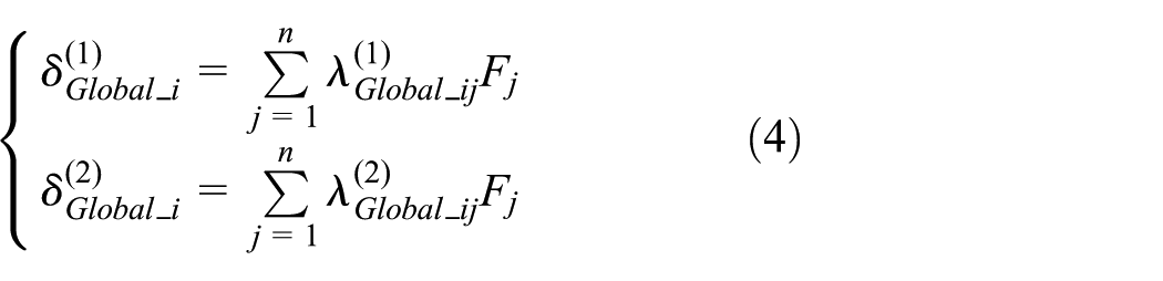
The deformation of gears can be divided into two categories: global deformation which changes linearly with the applied force and local deformation which changes nonlinearly with the applied force. Thus, the equations can be rewritten as

where
As global deformation of pinion and wheel is related to applied force P linearly, they can be expressed as
where
The global deformation compliance of gears can be obtained as

where the global compliance matrix of each contact position can be obtained by finite element method and substructure method. 26 Considering the nonlinear relationship between local contact deformation and the applied force, the Hertzian contact deflection of interested contact point can be calculated by 27

where Fi is the applied force and dz refers to the gear width. k1 and k2 are the distances on the pinion and the gear between the contact point and the tooth center line along the direction of applied force; E and ν are Young’s modulus and Poisson’s ratio, respectively; and a refers to the half width of contact zone along the profile direction, which can be determined by

where ρ1 and ρ2 are the curvature radius of the pinion and gear, respectively.
The deformation compatibility condition of contact points can be written as

Each contact point can be coupled using LSTE, the contact equation of each engagement position will be written as

In above, the matrix form of loaded tooth contact equation can be written as

where [λ] Global is the compliance matrix of global deflection of contact point, {F} is the external load vector, {u} Local is the contact deflection of interested contact point, {d} is the odd clearance vector of contact point, and {ε} is the initial clearance vector of contact point.
The load distribution F and loaded static transmission error LSTE can be obtained using the iteration algorithm 26 to solve the nonlinear matrix equations.
The time-varying mesh stiffness of helical gears with certain errors can be written as

The static load balance equation can be written as

Here, the loaded composite mesh error of helical gears can be defined as

Therefore, the static load balance equation (12) can be rewritten as

Obviously, the loaded composite mesh error is related to mesh stiffness, distribution form of gear errors, and the applied force.
Dynamic model of helical gear system
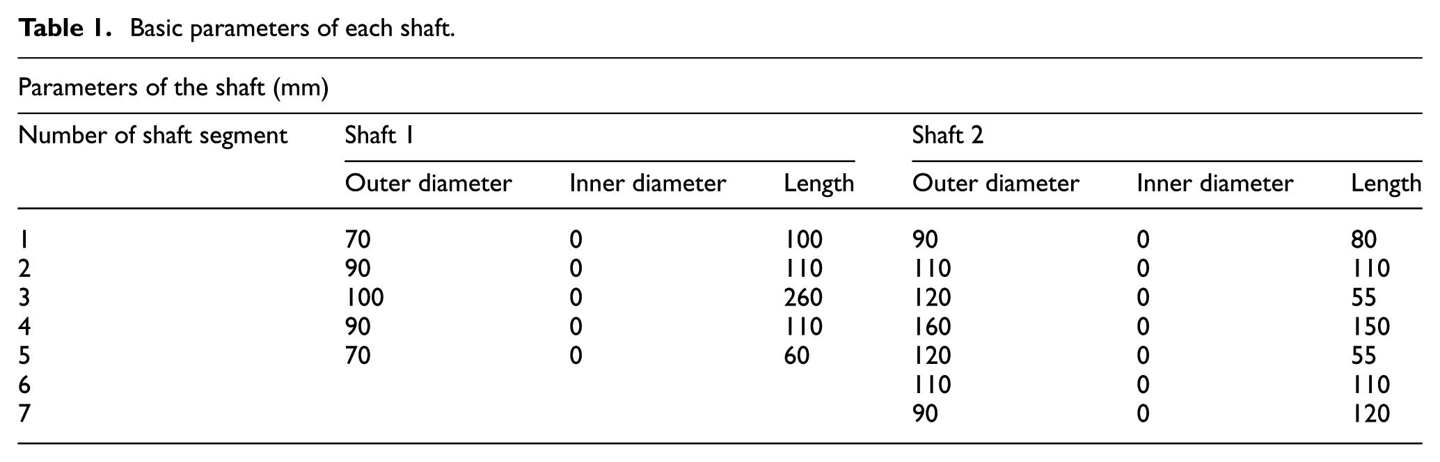
A simplified illustration of helical gear system and the corresponding generalized finite element model, which consists of three type nodes, namely, shaft node, bearing node, and power node, are shown in Figure 4. The parameters of each shaft are listed Table 1. In order to consider the effects of structure of shaft, the direction of power flow, and the supporting location of bearing on the dynamic responses of system, the helical gear system is divided into three elements: shaft element, mesh element, and bearing element. First, the dynamic model of shaft element is established by Timoshenko beam element. Second, the dynamic model of mesh element is developed by spring–damping–error element. Here, the stiffness of spring denotes time-varying mesh stiffness, and the error is loaded composite mesh error. In addition, the dynamic model of bearing element can be established by the stiffness and damping matrix theory of bearing. Finally, dynamic model of the system can be obtained by assembling dynamic model of each element based on the finite element method.

Schematic diagram of helical gear system.
Basic parameters of each shaft.
Modeling of shaft element
The dynamic model of shaft element is established by Timoshenko beam element with 2 nodes and 12 degrees of freedom, as shown in Figure 5. The generalized coordinate of Timoshenko beam element is defined as
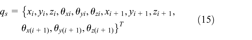
where xi, yi, zi, xi+1, yi+1, and zi+1 denote the translational displacement of each node along coordinate axes, and θxi, θyi, θzi, θx(i+1), θy(i+1), and θz(i+1) are the rotational displacement of each node around each coordinate axis.

Schematic diagram of shaft element.
Damping matrix of shaft element Cs can be calculated by Rayleigh damping

where α0 and α1 denote the mass coefficient and stiffness coefficient, respectively, and Ms and Ks are the mass matrix and stiffness matrix of shaft element, respectively.
When the mass matrix, stiffness matrix, and damping matrix are obtained, the motion differential equation in matrix form for shaft element can be written as

where stiffness matrix Ks and mass matrix Ms can be obtained based on basic theory of elastic mechanics. 28
Modeling of mesh element
The dynamic model of mesh element with 12 degrees of freedom is modeled by spring–damping–error element, as shown in Figure 6. The pinion and wheel are considered as two rigid disks that are connected by spring–damping at base circle, where β is the base helix angle; Op and Og denote the running center of pinion and wheel, respectively; rp and rg refer to the base circle of pinion and wheel; α is the mesh angle; ψ is the installation phase angle; xi, yi, zi(i = p, g) denote the translational displacement of pinion and wheel along each coordinate axis; and θxi, θyi, θzi(i = p, g) denote the rotational displacement of pinion and wheel rotating around each coordinate axis (Table 2).

Dynamic model of mesh element.
Basic parameters of the pinion and wheel.

The generalized coordinate vector of mesh element is defined as
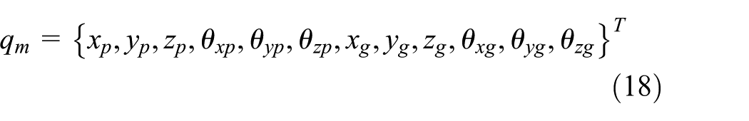
The relative displacement of pinion and wheel along the line of action can be expressed as

where the vector V refers to the projective vector from the coordinate of gear node to the line of action, which can be given as

where the plus sign in “±” and minus sign in “∓” are for anticlockwise rotation of pinion and the minus sign in “±” and plus sign in “∓” are for clockwise rotation of pinion.
Considering time-varying mesh stiffness and loaded composite mesh error, the motion differential equation of mesh element can be given as

where
The time-varying stiffness matrix Km and damping matrix Cm of mesh element can be expressed as


The motion differential equation in matrix form for mesh element can be written as

where Mm is the mass matrix, e(t) is the loaded composite mesh error vector of each degree of freedom, and qm is the displacement vector of shaft node connected with gears.
Modeling of bearing element
Gear system is usually supported by gear housing and connected to foundation, ignoring the coupling effect between the flexibility of gear housing and gear system, and the bearing element can be considered as a spring–damping element which connects shaft node with foundation. The general stiffness matrix of bearing Kb can be given as

Actually, the stiffness of each degree of freedom of bearing is time varying and coupled with each other. Here, ignoring the time-varying characteristic of bearing stiffness and the coupling relationship of different degrees of freedom, namely, the nonmain diagonal element of stiffness matrix, is zero.
The motion differential equation in matrix form for bearing element can be written as

where Mb denotes the mass matrix of bearing, Cb is the damping matrix of bearing which is identical with stiffness matrix of bearing, and qb is the displacement vector of shaft node connected with bearings.
Modeling of gear system
Based on the basic theory of finite element method, the global dynamic model of the system can be obtained by assembling dynamic model of each element. The global motion differential equation in matrix form for the system can be written as

where M is the global mass matrix; C is the global damping matrix; K(t) is the global stiffness matrix; x(t) is the generalized coordinates of finite element nodes; e(t) refers to the vector of loaded composite mesh error, which is equal to zero at each degree of freedom except degrees of freedom of mesh element; and F is the external force vector.
The static balance equation of the system can be written as

where xs(t) is the static displacement vector considering the deformation of shaft and bearing.
Vibration exciting force
Approximate transformation
The matrix form of motion differential equation (27) for the system can be rewritten as

Denote K(t) as the summation of mean value and fluctuation, which is

Substituting equation (30) into equation (29) and combining with equation (28) yields

As x(t) is not known yet, and the difference between x(t) and xs(t) is small enough to be ignored for helical gears, replace x(t) on the right side of the equation by xs(t). Then, the motion differential equation for the system can be written as

With the deduction above, the original time-variant differential equation (29) has been transformed into time-invariant differential equation (32). The right side of the equation K0xs(t) is time varying. Obviously, the K0xs(t) determines the vibration degree of gear transmission. Here, the K0xs(t) is defined as vibration exciting force.
The dynamic displacement x(t) can be expressed as Fourier series as

where ωm is the mesh frequency and n denotes the maximum order of Fourier series.
As same as x(t), the vibration exciting force K0xs(t) can be denoted as Fourier series as

Substituting equations (33) and (34) into equation (32) yields linear equations as

where ωk = iωm (i = 1, 2, …, n). Substituting Ai and Bi into equation (33) after solving equations (35), the dynamic displacement x(t) of each node can be obtained.
The dynamic transmission error of the system can be determined as

The dynamic bearing force of the system can be calculated as

where DBFx, DBFy, and DBFz are dynamic bearing forces in the x, y, and z directions, respectively. kb and kr denote the radial stiffness and tangential stiffness of bearing. cb and cr are the radial damping and tangential damping of bearing. xb, yb, and zb are dynamic displacements of bearing node along corresponding coordinate axis, respectively.
Comparison of solution methods
With the analysis and deduction above, the origin time-variant differential equation (29) is transformed into time-variant differential equation (32) by approximate transformation in order to improve calculation efficiency by Fourier series method. In order to validate the accuracy of approximate transformation, the dynamic responses of helical gear system with 10 µm of parabolic tip relief in three-tooth engagement zone are calculated by Newmark-β method and Fourier series method, respectively.
The root mean square (RMS) values of dynamic transmission error of the system in different speeds of pinion which are solved by the two methods are shown in Figure 7. It can be seen that the calculation result of the proposed method is very close to that of Newmark-β method, and the maximum relative error in all speeds of pinion is less than 4.2%. It indicates that the approximate transformation is feasible, and the precision of calculation is ensured perfectly.

Comparison of Newmark-β method and proposed method.
Numerical results and discussion
Global brute force optimization
Traditional optimization algorithm has the problem of local convergence, and the effect of design variables on the trend of the objective function cannot be captured. However, the improved LTCA model is of high efficiency because the global deformation compliance of interested tooth surface needs to be calculated only once. Therefore, the optimal solution of bias modification can be obtained by the direct calculation of the global sweep in the potential range of the modification parameters.
It can be known that the degree of vibration of gear system is determined by vibration exciting force from section “Vibration exciting force.” Thus, the optimization method of bias modification parameters aiming to minimize the fluctuation of vibration exciting force is proposed in order to reduce vibration and noise of the system. The region of amount of modification is from 0 to Ca, and the region of length of modification is from 0 to La. Here, Ca denotes two times of the deformation of helical gears in mesh-in position. The schematic diagram of optimization of bias modification for minimizing the fluctuation of vibration exciting force is shown in Figure 8. It can be seen that there is a narrow zone in which each modification parameter can reduce the fluctuation of vibration exciting force significantly. It is easy to select the optimal bias modification parameters for the helical gear system from Figure 8. The optimal amount of modification is 0.85Ca, namely, 10.1 µm. The optimal length of modification is 0.75La, namely, 17.1 mm.

Optimization of bias modification for minimizing the fluctuation of vibration exciting force.
The time-varying mesh stiffness and loaded composite mesh error of helical gears with bias modification are shown in Figure 9, and the corresponding load distributions are displayed in Figure 10. It can be observed that the load distributions of modified helical gears at mesh-in and mesh-out positions are smaller than that of unmodified helical gears but not equal to zero. That is to say, the tooth surface is still under fully contact condition. Therefore, the time-varying mesh stiffness curve of helical gears with bias modification is very close to that of unmodified gears. With the nonlinearity of contact deformation and change of load distribution, the maximum reduction of time-varying mesh stiffness in a mesh cycle is less than 0.8%. It is also observed that the shape of loaded composite mesh error is consistent with that of time-varying mesh stiffness, and the fluctuation of loaded composite mesh error 1.4 µm is far less than the maximum amount of bias modification, which is 10.1 µm. This is because loaded composite mesh error is not only related to amount of bias modification but also to the number of mating gear teeth and loaded tooth contact condition.
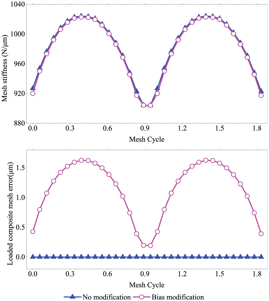
Effect of bias modification on time-varying mesh stiffness and loaded composite mesh error.

Effect of bias modification on load distribution of helical gears: (a) unmodified and (b) modified.
Dynamic responses analysis
The dynamic transmission error of the helical gear system and dynamic bearing force of bearing 2 in operating speed of pinion with 2000 r/min are shown in Figure 11. The results show that bias modification has significant effect on reduction of vibration of the system. As a result of intentional gear errors introduced by bias modification, the mean value of dynamic transmission error increases from 11.3 to 12.4 µm, about 9.8%, but the fluctuation of that decreases from 3.1 to 0.05 µm, about 98.5%. Meanwhile, the fluctuations of dynamic bearing force along the x and z directions reduce about 98.8% and 97.7%, respectively.

Effect of bias modification on dynamic responses of helical gear system: (a) dynamic transmission error, (b) dynamic bearing force in the x direction, and (c) dynamic bearing force in the z direction.
Figure 12 shows the RMS values of dynamic transmission error in regions of speeds of pinion from 0 to 6000 r/min. It can be observed that the torsional resonance speed of the system is about 4000 r/min. Harmonic resonances of the system occur in many times when the speed of pinion is less than 4000 r/min, and the corresponding amplitudes of harmonic resonance are much less than that of torsional resonance. The RMS values of dynamic transmission error of helical gear system will reduce remarkably in all speeds of pinion owing to optimal bias modification.
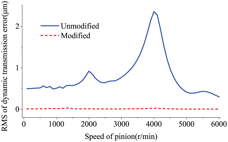
RMS of dynamic transmission error of helical gear system at different speeds of pinion.
Sensitivity to gear misalignment
It is well known that gear misalignment is a common and inevitable problem in gear transmissions that has an important influence on the contact condition of mating gear teeth and dynamic response of gear system. Some gear misalignments are caused directly by manufacturing and assembling errors, but others may be mainly related to bending and torsional deformation of shafts, deformation of gearbox during power transmission, or bearing clearances. It is obvious that the cause of gear misalignment is complicated, and it is difficult to predict and measure precisely.
Although the cause of gear misalignment is various, it can be divided into three categories: parallel misalignment due to center distance change, angular misalignment parallel to the plane of action (LOA misalignment), and angular misalignment perpendicular to the plane of action (OLOA misalignment).25,29 LOA misalignment refers to relative angular displacement between the meshing tooth surfaces of pinion and wheel around an axis which is perpendicular to the plane of action, the effect of which on contact condition of mating gear teeth and dynamic response of gear system is most significant. Therefore, only LOA misalignment is considered in this section, and it can be modeled as helix deviation,30,31 as shown in Figure 13.

Definition of gear misalignment.
In total, four cases of gear misalignment which is from 0 to 36 µm with step of 12 µm are designed in order to investigate the effect of gear misalignment on quasi-static and dynamic behaviors of modified gear system. The effects of gear misalignment on time-varying mesh stiffness and loaded composite mesh error of modified helical gears are shown in Figure 14. The results show that both time-varying mesh stiffness and loaded composite mesh error curves are changed due to gear misalignment. With the increase in gear misalignment, the time-varying mesh stiffness will decrease, but loaded composite mesh error will increase notably. The mean values of time-varying mesh stiffness reduce about 3.8%, 17.9%, and 30.5% for 12, 24, and 36 µm gear misalignment, respectively, and the corresponding mean values of loaded composite mesh error increase about 478.1%, 788.1%, and 982.1%.

Effect of gear misalignment on time-varying mesh stiffness and loaded composite mesh error (the corresponding straight dot line denotes mean value of time-varying mesh stiffness).
The effect of gear misalignment on the fluctuation of vibration exciting force is shown in Figure 15. It can be seen that the fluctuations of vibration exciting force increase nonlinearly with the increase in gear misalignment. The fluctuations of vibration exciting force of unmodified helical gear system increase about 4.1%, 7.9%, and 40.4% for 12, 24, and 36 µm gear misalignment. For modified helical gear system, the fluctuations of vibration exciting force increase 951.7%, 2824.4%, and 5122.7%, respectively. Compared with unmodified helical gear system, the fluctuations of vibration exciting force of modified helical gear system reduce 98.0%, 79.5%, and 45.0% for 0, 12, and 24 µm gear misalignment. When gear misalignment is 36 µm, the reduction is only 24.5%. This is because gear misalignment will change the load distribution of mating gear teeth, as shown in Figure 16. It can be observed that increasing gear misalignment will lead to appearance of a partial contact loss through the face width. When gear misalignment is larger than 24 µm, the actual length of contact line of mating gear teeth will reduce remarkably, and the contact loss will become very serious.

Effect of gear misalignment on the fluctuation of vibration exciting force.

Effect of gear misalignment on load distribution of modified helical gears: (a) without gear misalignment, (b) 12 µm gear misalignment, (c) 24 µm gear misalignment, and (d) 36 µm gear misalignment.
The effects of gear misalignment on dynamic transmission error of helical gear system with and without bias modification are displayed in Figure 17. It can be seen that increase in gear misalignment will bring larger vibration of both unmodified and modified helical gear systems. Due to decreased mesh stiffness, the lower resonance speed of pinion will become lower with the increase in gear misalignment. Bias modification has a well reduction of vibration and noise of system when gear misalignment is relatively small, namely, less than 12 µm. The corresponding RMS value of dynamic transmission error reduces more than 80% in operating speed of pinion. The bias modification has little effect on reduction of system vibration when gear misalignment is larger than 32 µm. In operating speed of pinion, the corresponding RMS value of dynamic transmission error decreases only less than 17%.
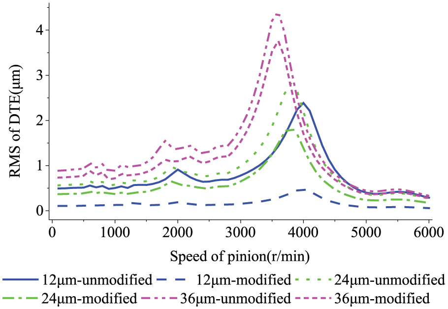
RMS of dynamic transmission error of helical gear system.
Conclusion
The influence of optimal bias modification on quasi-static and dynamic behaviors of helical gear system and the sensitivity of vibration of the system with optimal bias modification to gear misalignment have been studied in this article. The dynamic model of the system is developed using the finite element method and Timoshenko beam theory, and the vibration exciting force is separated through approximate transformation which was validated by comparing with numerical integration method. Aiming to minimize the fluctuation of vibration exciting force, the optimal modification parameters are determined using global brute force optimization method based on improved LTCA model. The effects of optimal bias modification on time-varying mesh stiffness, loaded composite mesh error, and load distribution of helical gear system with and without gear misalignment are investigated. The influences of gear misalignment on the effectiveness of reduction of vibration of helical gear system with optimal bias modification are also analyzed. The main conclusions are summarized as follows:
The time-variant differential equations of dynamic model of helical gear system are transformed into time-invariant differential equations which can be solved faster by Fourier series method. The approximate transformation provides sufficient precision and greatly increases the computation efficiency. Meanwhile, the internal excitation of helical gear system, defined as vibration exciting force, can be observed clearly.
Optimal bias modification has little effect on time-varying mesh stiffness of helical gears. Owing to full contact of tooth surface of helical gears with optimal bias modification, the time-varying mesh stiffness curve of modified helical gears is very identical with that of unmodified ones. The corresponding RMS values of dynamic transmission error and fluctuation of dynamic bearing force will decrease remarkably.
Gear misalignment will increase the vibration of helical gear system and result in lower resonance speed because of decreased mesh stiffness. Bias modification shows a well reduction of vibration of helical gear system when gear misalignment is relatively small. When gear misalignment is too large, more serious contact loss will be observed, and robust optimization should be considered.
Footnotes
Handling Editor: Yunn-Lin Hwang
Declaration of conflicting interests
The author(s) declared no potential conflicts of interest with respect to the research, authorship, and/or publication of this article.
Funding
The author(s) disclosed receipt of the following financial support for the research, authorship, and/or publication of this article: This work was supported by the National Natural Science Foundation of China (grant nos 51535009 and 51605040) and 111 Project (grant no. B13044), China.