
Abstract
Dynamic performance is an important index of high-speed on/off valve in the digital hydraulic field. Optimizing the control algorithm is an effective method to improve the dynamic performance of existing high-speed on/off valves. Usually, a high-voltage excitation method is used to realize fast switching of the high-speed on/off valve, but this also leads to a high temperature rise, large energy consumption, and long delay times when switching off. In this article, an intelligent pulse-width modulation control algorithm is proposed to improve dynamic performance while minimizing temperature rise and energy consumption of high-speed on/off valves. A high-frequency voltage source with full positive, low positive, full negative, and zero duty ratios is applied to drive the high-speed on/off valve in opening, maintaining opened, closing and maintaining closed states, respectively. The adaptive switching of these four duty ratios is realized by real-time current feedback which can estimate the operational state of the high-speed on/off valve, so that the current in the loop is always in the optimal state. A mathematical model of the high-speed on/off valve is built, and based on it, the theoretical formulas for the delay time, temperature rise, and energy consumption of the high-speed on/off valve are deduced. Simulation results indicate that the intelligent pulse-width modulation control algorithm has a better performance in dynamic characteristics than normal high-voltage excitation methods. Moreover, experimental results from a test system indicate that the intelligent pulse-width modulation control has the potential to shorten the opening time by 23.6% and closing time by 17.0%, which confirms the simulation results. Results also showed the ability to extend the controllable working duty ratio by 83.3%, to reduce temperature rise by 69.9%, and reduce energy consumption by 88.8% when compared to the matched controller of the tested high-speed on/off valve. This article presents an effective and practical method to improve the performance of high-speed on/off valves.
Keywords
Introduction
The high-speed on/off valve (HSV) is a typical digital component and is widely used in hydraulic and pneumatic systems because of its advantages, such as excellent switching performance, compact structure, anti-pollution abilities, and low cost. Operation frequency and rated flow are two important indexes to evaluate the performance of a HSV. Therefore, improving the dynamic performance of an HSV to extend its operation frequency is always a research hotspot. The methods to enhance the dynamic performance of HSVs mainly include optimizing the control algorithm and valve structure, and improving the performance of the actuator. To improve the control algorithm, Florian and Rudolf 1 proposed a valve current boost method to keep current at different levels, which was actually realized by voltage square waves with different duty ratios, so as to shorten the switching time. In the study of Lee, 2 a fast HSV response was achieved using three power sources driving circuit, but the excitation time of each power source was preset, which needed accurate calculations and tests to determine an optimal excitation time of each power source. In valve structures, Stockner et al. 3 presented a hollow spool structure to decrease the spool mass so as to improve dynamic performance. Tu et al. 4 designed a rotary on/off valve, which spun its spool to switch the operational state, and the prototype spool had reached selfspinning over 90 Hz. Ruan et al. 5 designed a two-dimensional (2D) valve whose spool has 2 degrees of rotary and sliding freedom, which can realize a fast response. As to the actuator of the HSV, a lot of work has been done. As early as 1979 and 1981, some special solenoid structures were proposed to accelerate the armature.6,7 In the literatures,8–10 the finite element method was used to optimize the solenoid actuator to achieve faster responses. Man et al. 11 used a permanent magnet shield in the electromagnetic actuator to improve dynamic performance for high-pressure applications. In the study of Takahiro 12 and Goodfriend et al., 13 a giant magnetostrictive material was used to make the electromagnetic actuator, which improves its maximum output force to achieve a faster response.
However, with the increasing importance of energy efficiency, the topics in reducing temperature rise and energy consumption of HSVs have also gradually become a research focus. In order to realize low energy consumption, Pellikka et al. 14 combined computation of finite element methods with genetic optimization to design a solenoid actuator, which has a better energy-saving performance. Sheng-Nian et al. 15 employed a soft switch to constitute a driving control scheme for HSVs and achieved a good energy characteristic. Ling et al. 16 discussed the parameters of pulse-width modulation–holding solenoid drive mode, which decreased the holding current. Goraj 17 studied the influence of the pulse-width modulation (PWM) method on the temperature distribution in the armature of HSVs. Cheng et al.18,19 studied the effects of four different driven strategies on the power losses of high-speed solenoid injector. It was found that driven circuit optimization was one of the most efficient methods to reduce the power loss. Zhao et al. 20 investigated the effects of different boost voltage on the dynamic response and energy losses of HSVs and pointed out that there was an optimal boost voltage to reach the highest energy utilization efficiency of HSVs. In the study of Giousouf and Kovacs 21 and Hill et al., 22 dielectric elastomer (DE) membrane actuators which have a low energy consumption were used to drive the switching valves; compared with the solenoid valve, the DE valve can effectively decrease the energy consumption from 2.25 J to 5.7 mJ.
Improving the valve structure and actuator has to be done in the design stage of the HSV and cannot improve existing HSVs. Therefore, using a high voltage to drive the solenoid to achieve a large magnetic force is an effective and frequently used method to improve the dynamic performance of the existing HSVs but will also lead to higher cost and higher temperature rise. In the above papers,1–22 methods can improve either the dynamic performance or temperature rise characteristics but still have some limitations when combining both. In order to solve this contradiction, an intelligent and practical method for both improving dynamic performance and reducing temperature rise of high-speed on/off solenoid valves is presented in this article. A voltage source with an adjustable duty ratio is used to drive the HSV but different from the literatures.1,2 The active time of each excitation voltage with a different duty ratio can be adaptively changed according to the control signal from the controller and the current signal from the circuit. The ideal operation state for the HSV at each state will follow the following rules: a voltage with full positive duty ratio drives the HSV rapidly, a voltage with low positive duty ratio keeps the HSV opened, a voltage with full negative duty ratio closes the HSV quickly, and a voltage with zero duty ratio keeps the HSV closed. Each switching of the duty ratio is realized by signal triggering and the current feedback principle.
This article is organized as follows. First, a mathematical model of a tested HSV is built and then the theoretical delay time of switching processing is deduced. Based on them, the method to improve switching performance and reduce temperature rise is concluded. Second, the intelligent PWM control method is introduced, and the numerical simulation of the dynamic performance of the HSV switching process is carried out. Finally, a special hydraulic test HSV system is built to measure dynamic performance and temperature rise, and a set of experiments are carried out to verify the improvements on dynamic performance and energy efficiency by the intelligent PWM control.
Structure of the HSV
In this article, an HSV-3203S7 HSV is used as the study object. It is a two-position, three-way, resting state closed HSV and is jointly developed by Guizhou Honglin Machinery Company, China and BKM Company, America. A schematic structure is shown in Figure 1. According to manufacturer’s specifications, the rated pressure is 20 MPa, and the rated flow rate is about 2.5 L/min.

Structure of the tested high-speed on/off valve. (1) Supply ball, (2) separating pin, (3) returning ball, (4) valve housing, (5) push rod, (6) pole shoe, (7) armature, and (8) coil.
Instead of the traditional spring structure, this HSV operates without a reset spring but relies on the hydraulic pressure from the inlet P. When the coil is energized, the supplying ball, returning ball, and separating pin are moved to the right by the electromagnetic force. As a result, operating port A is connected to inlet P and disconnected to outlet T. When the coil is de-energized, the pin and balls are moved to the left by the hydraulic pressure from port P. As a result, the operating port A is connected to outlet T and disconnected to inlet P.
Theoretical analysis
Dynamic performance analysis
The dynamic performance of the high-speed solenoid valve can be described by the following models: the electrical circuit model, the magnetic circuit model, and the dynamic mechanical model.
The electrical circuit model can be written as

where U is the driving voltage, R is the equivalent resistance, I is the current of coil, and L is the equivalent inductance.
The magnet circuit model can be written as


where
The dynamic model of moving parts can be written as

where x is the displacement of the moving part,
Because there is a steady flow force acting on the operation port, the critical electromagnetic force can be written as

where
By combining equations (2), (4), and (6), the critical current can be written as

where
Under fixed operating conditions, the trigger engagement and disengagement of the solenoid are constant, and the corresponding engaged current
The transient process of the coil current can be written as

where

where
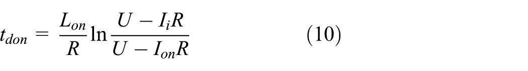

where
It can be seen from equations (10) and (11) that large values of initial currents and excitation voltages are helpful to reduce
Temperature rise and energy consumption analysis
The temperature rise equation of the coil can be written as

where
The thermal power equation of the coil can be written as

where P is the average thermal power,
Working principle of intelligent PWM control
In this section, an intelligent PWM control method is presented, which consists of a voltage source, a current detector, and a controller. The hardware setup is shown in Figure 2. The voltage is used as a power source to drive the HSV. The controller directs the voltage source to provide a high-frequency PWM (more than 10 kHz) with four different duty ratios: full positive duty ratio, low positive duty ratio, full negative duty ratio, and zero duty ratio, which are applied to drive the HSV in opening, maintaining open, closing, and maintaining closed processes, respectively. Every high-frequency PWM with a duty ratio can be regarded as an analog power source. It is important to determine the active durations of full positive duty ratio and full negative duty ratio because too short a duration of full positive duty ratio will not engage the electromagnet successfully, and too long a duration will cause a larger current and higher temperature rise. Similarly, too short a duration of negative full duty ratio will not disengage the electromagnet successfully, and too long a duration will cause a negative current. A large enough negative current will engage the electromagnet again and destroy the operational stability of the HSV. In order to overcome this problem, a current feedback principle is applied to estimate the operation state of HSV so that the controller automatically changes the duty ratio of the PWM according to the feedback values from the current detector and the control signal from the operator.

Hardware setup.
The operation principle of the controller is shown in Figure 3. The control signal generated by the operator is used to control the operation frequency and duty ratio of the HSV. Before this control algorithm starts, the engaged current
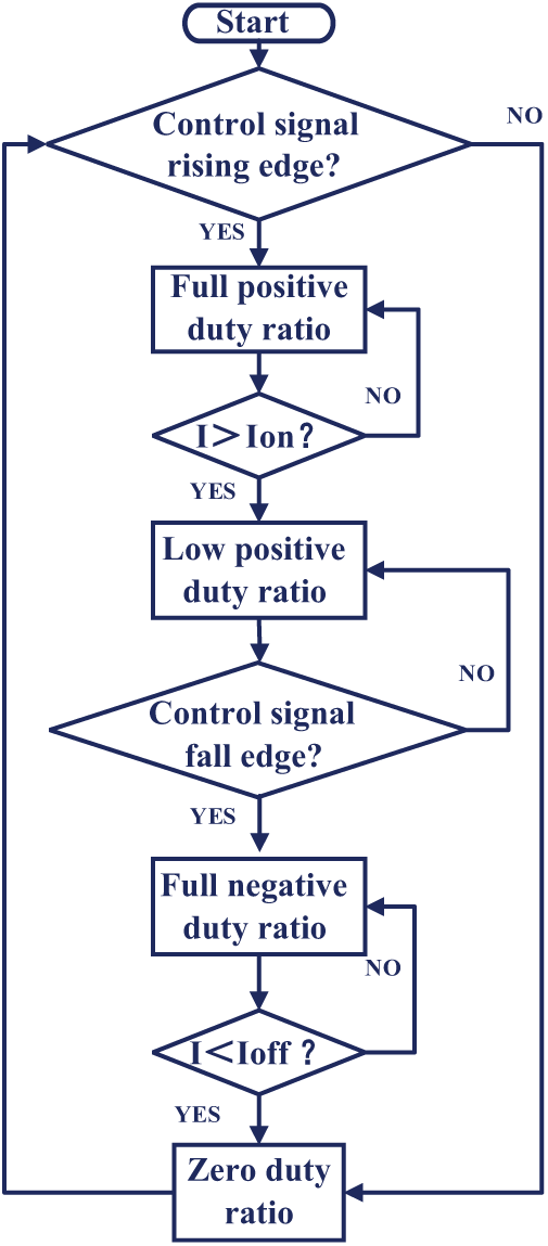
Control flowchart.
Once the system starts, the control signal begins at a high level, and the controller directs the voltage source to operate at a full positive duty ratio. Under the excitation of maximum voltage, the current raises to
Under this intelligent PWM control algorithm, a maximum voltage level can achieve a fast response in the engaging process, and current begins to drop automatically once it reaches the engaged current trigger value, which can effectively avoid a useless additional increase of current in the coil. Voltage with an appropriate low positive duty ratio is able to maintain the electromagnet’s state while also making the initial current lower at the moment of disengagement and decreasing
Benefiting from the adaptive switching of different duty ratios, the current is always in the optimal state during the entire process, as shown in Figure 4. Improving upon methods which need to preset the active time of each voltage or corresponding duty ratio, the proposed method uses currents as feedback signals to realize the adaptive switching of different duty ratios. Even under the influence of varying coil resistance caused by temperature increases, the switching time of each duty ratio can be adjusted adaptively. Therefore, this method not only effectively improves the working frequency of HSVs but also reduces the current in the coil, lessens temperature increase during valve operations, extends the service life, and realizes energy savings.

Current characteristics under the intelligent PWM control.
Numerical simulations
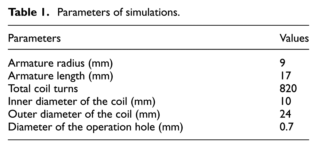
The dynamic models of the tested HSV with algorithms of a matched controller and an intelligent PWM control are established as the experimental system, which is shown in Figure 6. By disassembling the tested HSV, some basic parameters are obtained in numerical simulations and shown in Table 1.
Parameters of simulations.
The simulation results are built with a supply pressure of 20 MPa and shown in Figure 5. The comparison of the two control methods are shown in Table 2. It could be seen that the delay time and switching time are shortened greatly by adopting the intelligent PWM control algorithm.

Simulation results of transient pressure of port A: (a) switching on and (b) switching off.
Simulation comparison of the dynamic performance.
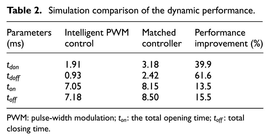
PWM: pulse-width modulation;
Experiment and results
Experimental setup
It is difficult to measure the dynamic performance of the tested HSV directly by a conventional displacement sensor because the HSV has a special ball structure. However, the pressure at port A can be used to evaluate the switching performance of the HSV, as shown in Figure 6, and its experimental setup is shown in Figure 7. The smaller the volume of the chamber connected to port A, the more accurate the results will be. 23 The chamber volume connected to port A in the tested valve block is about 1 cm3. An infrared thermometer is used to detect the real-time temperature on the surface of the valve coil. By actual measurement, it is known that the equivalent resistance of the circuit is 10.8 Ω, the equivalent inductance in the engaged initial position is about 60 mH, in the disengaged initial position is about 68 mH, and the currents for opening and closing states are 0.65 and 0.27 A, respectively. In order to ensure the HSV is fully switched, the engaged current trigger value is set as 0.8 A, and disengaged current trigger value is set as 0.2 A.
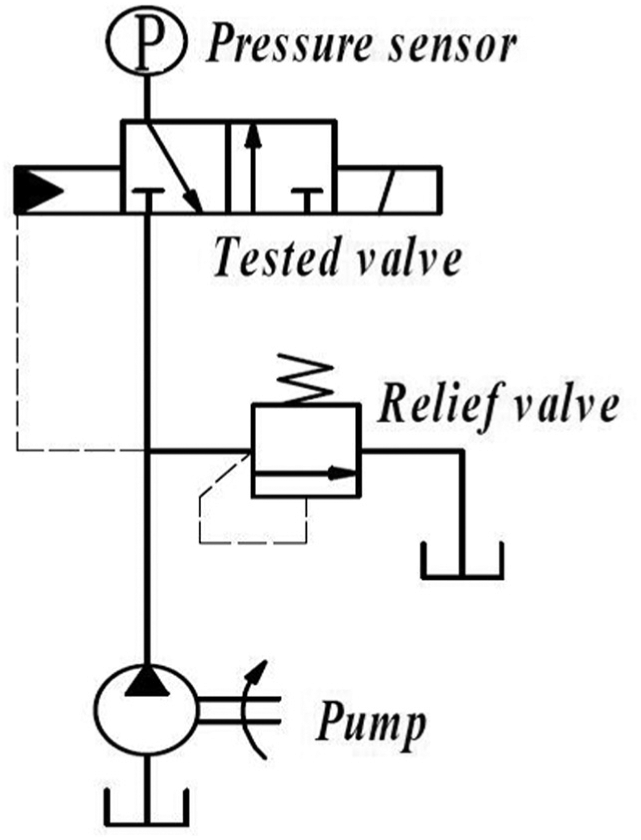
Principle of experimental system.
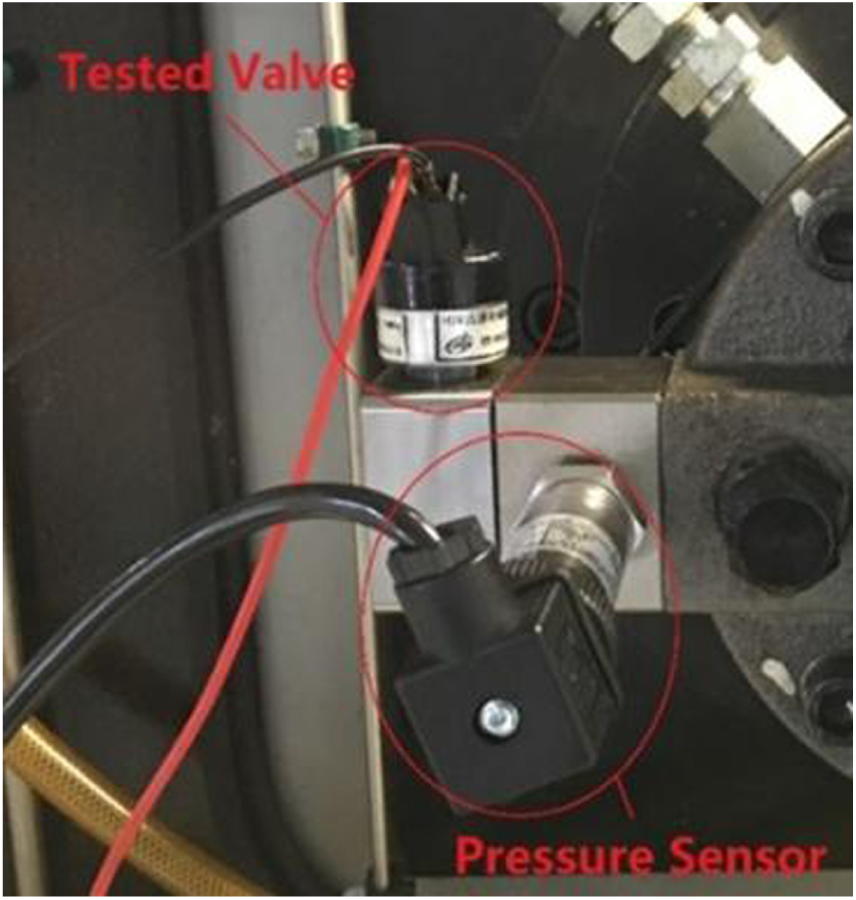
Picture of the experimental system.
In the experimental setup, a NI 9505 DC servo driver board with a maximum input voltage of 30 V is used to drive the HSV. Therefore, the low positive duty ratio is set as 0.17, which will result in a hold current 0.2 A larger than the tested closing current value to maintain the HSV in the open state. This driver board can output high-frequency PWM (<40 kHz) of various duty ratios. With an embedded current detection module, this driver board is able to detect the circuit current with an update speed of 20 μs for the real-time operation system. The operation frequency of this driver board is set as 30 kHz, and the full duty ratio, low duty ratio, negative duty ratio, and zero duty ratio are set as 100%, 17%, −100%, and 0%, respectively.
Experimental results
A mature controller for the HSV is used in this article and shown in Figure 8. With a 24 V rated input voltage, the matched controller will generate a positive voltage during the whole opening operation but a negative voltage at the beginning of closing operation.

Picture of the HSV controller.
A series of experiments have been performed under a supply pressure of 20 MPa. The dynamic performance of the HSV under the matched controller is shown in Figure 9. From Figure 9(a) and (b), it is seen the total opening time is 11.67 ms including a delay time of 3.49 ms. The total closing time is 9.58 ms including a delay time of 0.90 ms. Figure 9(c) and (d) show the critical working duty ratios of the HSV at the operation frequency of 50 Hz. Adjusting the duty ratios of high voltage to 38% and 74%, it is seen that the HSV can work normally, but it is close to the critical state. The HSV will not be opened totally if the duty ratio is less than 38% and also will not be closed totally if the duty ratio is greater than 74%.
Dynamic performance of the HSV under a matched controller: (a) switching on, (b) switching off, (c) minimum controllable duty ratio (38%), and (d) maximum controllable duty ratio (74%).
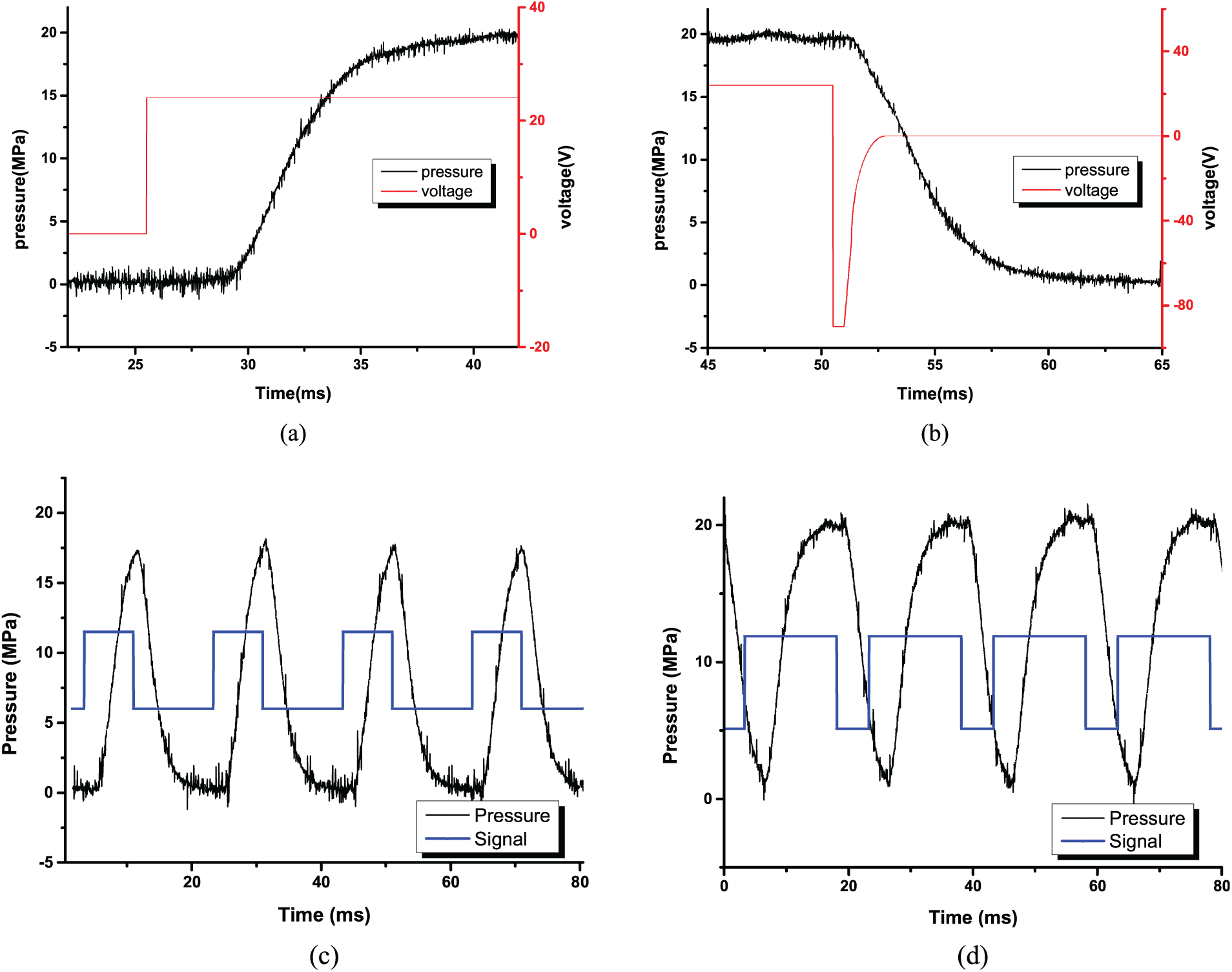
Figure 10 shows the dynamic performance of the HSV with an intelligent PWM control. Figure 10(a) and (b) shows the opening time, including the delay time of 1.54 ms, is 8.91 ms, which is shorter by 23.65% when compared to the matched controller. The closing time, including the delay time of 0.63 ms, is 7.95 ms, which is shorter by 17.01% when compared to the matched controller. Figure 10(c) and (d) shows that the critical operation duty ratios, under a control signal of 50 Hz, are 15% and 81%, respectively. It is an expansion of 83.3% when compared to the matched controller.

Dynamic performance of the HSV with an intelligent PWM control: (a) switching on, (b) switching off, (c) minimum controllable duty ratio (15%), and (d) maximum controllable duty ratio (81%).
Figure 11 shows the frequency performance of the HSV with a control signal of 100 Hz and 50% duty ratio. The curve in Figure 11(a) illustrates that the HSV can switch normally, but the peak value of the curve in Figure 11(b) is about 13 MPa. This means that the HSV is not able to open completely under this condition. The intelligent PWM control therefore effectively improves the maximum working frequency of the HSV.

Frequency performance of the HSV with different control methods: (a) intelligent PWM control and (b) matched controller.
As shown in Figure 12, the initial currents of the HSV switching off with a matched controller and an intelligent PWM control are 2.25 and 0.45 A, respectively. But for switching on with a matched controller, they both are about 0.04 A. As shown in Table 3, the delay times could be evaluated by equations (10) and (11).

Current characteristic in the coil.
Theoretical evaluation of switching response.
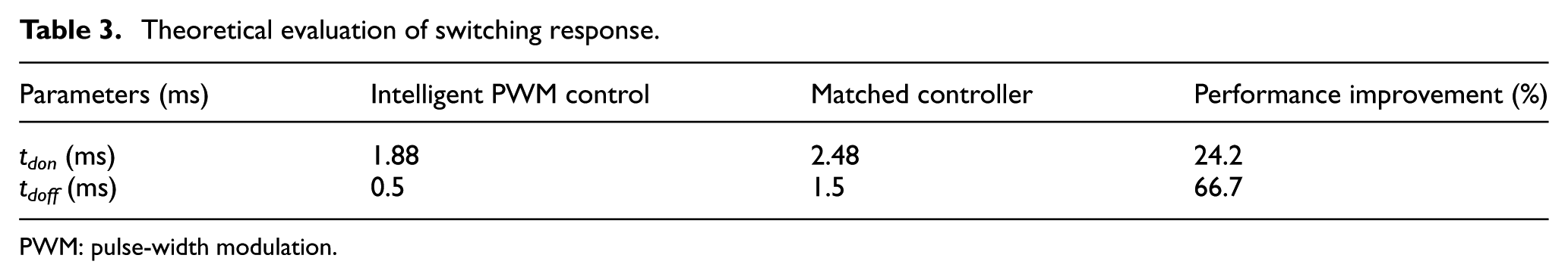
PWM: pulse-width modulation.
In order to study the temperature increase in the valve, the current in the circuit under a control signal of 20 Hz and 50% duty ratio is measured and shown in Figure 12. Due to continuous supply of high voltages from the matched controller, the current increases after the valve opened. At the moment of closing, it leads to a high initial current, a long time tdoff as well as a high temperature in the coil, and has a negative influence on the service life of the HSV. However, with the intelligent PWM control, the duty ratio of the excitation voltage is changed adaptively, and it effectively ensures that the HSV is fully switched and the current is kept in an optimal state simultaneously. Based on the curves in Figure 12 and equation (13), the heat energy consumptions are calculated as 23.44 and 2.62 W for the matched controller and the intelligent PWM control, respectively. The energy-saving reaches to a dramatic number of 88.8%.
In this working condition, the temperature increase in the valve is measured under a room temperature of 26°C as shown in Figure 13. When the valve is under the intelligent PWM control, there is no significant change in temperature and stabilizes on a value of about 28°C. However, when the valve is driven by the matched controller, the valve temperature rapidly increases and stabilizes about 93°C after 5 min. Moreover, a faint odor of burning plastic can be smelled around the tested HSV after about 30 min. This means the plastic wrapped outside the coil has a tendency to melt. Finally, it is found that the intelligent PWM control effectively reduces the temperature increase by 69.9% and greatly extends the service life of the HSV. A comparison of the two methods in experiments is summarized in Table 4.

Temperature rise characteristic of the coil.
Experimental comparison of the two methods.

PWM: pulse-width modulation.
Result analysis
In summary of the proposed theoretical evaluation, simulation analysis and experimental measurements, it indicates that the intelligent PWM control algorithm can effectively improve the dynamic performance. Experiment results show that the intelligent PWM control algorithm has great potential to reduce the temperature rise and power consumption. Moreover, the resultant errors of the proposed methods could be caused by the lag of the pressure relative to the displacement of the spool, the temperature changing of the oil, and the shape of testing chamber. These factors affecting experimental results were not considered in numerical simulations.
Conclusion
In this article, an intelligent PWM control method for HSV is proposed, and the dynamic performance, power consumption, and temperature characteristics of a HSV are investigated. Theoretically, the intelligent PWM control method can achieve a good dynamic performance while reducing temperature rise and power consumption. Both the simulation and experiment results demonstrate that the proposed intelligent PWM control method has obvious advantages compared to the matched controller. Using the intelligent PWM control, the opening time and closing time are shortened by 23.6% and 17.0%, respectively, and the controllable working duty ratio is extended by 83.3%. The rise in temperature is also decreased by 69.9% during valve operation, and the energy consumption of the valve is reduced by 88.8%.
In the future study, the limit of the maximum input voltage of the NI 9505 DC servo driver board could be increased, and the intelligent PWM control method will give full play to its advantage and has great potential to improve the switching performance of HSVs while combining a good temperature and energy characteristics.
Footnotes
Handling Editor: Rahmi Guclu
Declaration of conflicting interests
The author(s) declared no potential conflicts of interest with respect to the research, authorship, and/or publication of this article.
Funding
The author(s) disclosed receipt of the following financial support for the research, authorship, and/or publication of this article: This project was supported by the National Key Technology Support Program of China (grant no. 2014BAF 02B00) and National Science and Technology Major Project of China (grant no. 2012ZX04004021).