
Abstract
Steer-by-wire system has replaced the conventional mechanical linkages with electronic actuators. In this article, a joystick is utilized to substitute the conventional steering wheel and study the variable steering ratio design methods in this new human–machine interface. With this structure of steer-by-wire system, the steering angle and torque ratio can be designed flexibly. A dynamic model of joystick of steer-by-wire system is built based on bilateral control scheme. Through comparing the vehicle steering performance of joystick with steering wheel, three conventional steering ratio design methods are studied that are speed-dependent, speed- and angle-dependent and constant yaw rate gain. The drawbacks are analysed by three kinds of conventional steering ratio, and a novel variable yaw rate gain steering ratio design method is investigated. A driving simulator is used to verify and compare these steering ratio design methods. The computer simulation and experimental test results demonstrate that the variable yaw rate gain steering ratio design method can effectively guarantee vehicle steering performance.
Introduction
X-by-wire (Xbw) technology offers the opportunity for developing vehicle dynamics and driver–vehicle interface (human–machine interface (HMI)) with enormous flexibility.1,2 The application of Xbw technology to vehicle steering system gives birth to the so-called steer-by-wire (Sbw) system. In such a system, the mechanical linkage between vehicle steering wheel and front road wheels is replaced with electronic controllers and actuators. Such a feature enables the Sbw system to have advantages over a conventional steering system in terms of improved driving comfort and enhanced vehicle handling. 3 In addition, the steering wheel in a Sbw system may be substituted by some advanced driver–vehicle interface, for instance, a joystick. 4 To use a joystick as an alternative to a steering wheel in a Sbw system may help further optimize cabin space utilization, reduce the risk of injury to drivers in collisions and integrate sophisticated vehicle dynamic control functions. 5
A key characteristic of the Sbw system is that the steering ratio of the vehicle, that is, the ratio of driver steering angle to front road wheel angle, can be designed with complete freedom. With regard to the design of the steering ratio, a great effort has been put into the Sbw systems where a conventional steering wheel is equipped as the driver–vehicle interface. Azzalini et al. 6 described a fuzzy adaptation approach to determine the steering ratio according to vehicle speed and driver steering angle. Heathershaw 7 proposed a steering ratio design method that reduces the level of vehicle understeer so as to increase vehicle characteristic speed during cornering. Tajima et al. 3 proposed the concept of ideal steering ratio which is derived from a speed-independent vehicle lateral response gain. The performance of the ideal steering ratio was validated through experiments using a driving simulator. Xu et al. 8 proposed a variable steering ratio design algorithm that aims at enhancing vehicle steady-state manoeuvrability and transient responses. Experiments using a driving simulator were conducted to verify the proposed algorithm. Kazemi and Janbakhsh 9 proposed a nonlinear adaptive sliding mode controller for a Sbw system to improve vehicle handling and stability and reduce the influence of system uncertainties. Chang 10 investigated a chaotic motion pattern of a Sbw system with variable steering ratio. Complex nonlinear behaviours of the system were observed. Yamaguchi and Murakami 11 described an adaptive control approach to attain the desired steering characteristics through road condition recognition on a vehicle equipped with active steering control. Simulation and experiments were carried out to validate the proposed approach. Zheng and Anwar 12 described a vehicle yaw stability control algorithm for a Sbw vehicle. The algorithm enables a decoupling of vehicle lateral and yaw motions through the feedback of yaw rate and front wheel steering angle. Fahimi 13 introduced an approach to control simultaneously the longitudinal, lateral and yaw dynamics of a four-wheel-steer (4WS) vehicle.
Despite the extensive work reviewed above, there is currently very little research on the design of the steering ratio for a Sbw system equipped with a joystick. When using a joystick instead of a conventional steering wheel to control a vehicle, the steering angle range would be very narrow compared to a conventional steering wheel. Nowadays, vehicles equipped with a conventional steering wheel normally have a steering angle range of 760°, that is, 380° in both clockwise and anticlockwise directions. In contrast, a joystick normally covers a steering angle range less than 60° due to the intrinsic impedance of human arms. There exists some research on the advancement of the controllability of the joystick itself. Kim et al. 14 proposed a method to improve the operability of a joystick steering device by taking into account the impedance of human arms. The method was validated through experiments. Park et al. 15 developed a new joystick that possesses a larger angle range. Such a joystick was tested capable of improving driving safety by preventing fast steering. Nevertheless, the determination of the steering ratio of a joystick Sbw system would still be an issue of importance. Towards this end, this article discusses four different methods for the design of steering ratio for a joystick Sbw system, namely speed-dependent, speed- and angle-dependent, constant yaw rate gain and variable yaw rate gain methods.
The remainder of the article is organized as follows. In section ‘Joystick Sbw model’, the modelling of the joystick Sbw system is described. In section ‘Variable steering ratio design methods’, four methods for design of variable steering ratio of a Sbw system are proposed one after another. In section ‘Simulation and experiments’, computer simulation and driving simulator experiments are designed and conducted to examine the effectiveness of the proposed design methods. Finally, conclusions are drawn in section ‘Conclusion’.
Joystick Sbw model
A Sbw system with a joystick as the driver–vehicle interface can be considered as a bilateral control system which is frequently applied to macro–micro teleoperation problems. 16 Figure 1(a) shows a bilateral teleoperation system consisting of five interacting systems including (1) a human operator, (2) a master manipulator, (3) a controller, (4) a slave manipulator and (5) environment. 17 The joystick Sbw system can be somehow delineated in a similar way in the sense of a bilateral control systems, as shown in Figure 1(b).

Bilateral control structure: a comparison between teleoperation and Sbw system: (a) bilateral control structure of a teleoperation system and (b) bilateral control structure of a Sbw system.
In Figure 1(a), Xh and Fh are the position and force applied by the operator, Xm and Fm are the position and force applied by the master manipulator and controlled by the controller, Xs and Fs are the position and force applied by the slave manipulator and controlled by the controller and Xe and Fe are the position and force applied by the slave manipulator to the environment, respectively. Analogously, in Figure 1(b), θh and Th are the joystick steering angle and steering torque, θm and Tm are the angle and torque controlled by the controller of the steering road feel motor, that is, the motor used to generate the steering road feel for the driver, θs and Ts are the steering system pinion angle and steering actuator motor torque and θe and Te are the front wheel angle and the tyre self-aligning torque, respectively. By applying the second law of Newton to the joystick block as shown in Figure 1(b) gives 18

where Jm is the moment of inertia of the joystick assembly and Bm is the viscous damping. Similarly, by applying the second law of Newton to the steering actuator block gives

where Je is the moment of inertia of the steering actuator and Be is the viscous coefficient

where Kmp and Kmd are, respectively, the proportional and derivative control parameters of the steering road feel motor controller, and is is the steering ratio of the joystick angle to front wheel angle, such as
The above model is built by MATLAB/Simulink and embedded in CarSim for computer simulation study. More details regarding the simulation study will be discussed in section ‘Simulation and experiments’.
Variable steering ratio design methods
Here, four methods for steering ratio design of a joystick Sbw system are discussed, respectively, in sections ‘Speed-dependent design’ to ‘Variable yaw rate gain design’, namely speed-dependent, speed- and angle-dependent, constant yaw rate gain and variable yaw rate gain. For all these four design methods, the range of joystick steering angle is set to be from −25° to +25° while that of the vehicle front road angle is set to be from −40° to +40°.
Speed-dependent design
In this section, a method involving designing the steering ratio of a joystick Sbw system as a function of vehicle speed is proposed. It can be imagined that when the vehicle is travelling at a relatively low speed, a smaller steering ratio would be desirable since it allows a driver to use less arm movement to negotiate a sharp curve. However, when the vehicle is travelling at high speeds, the driver would normally prefer larger steering ratios so that the vehicle becomes less sensitive to his or her arm movements, or in other words, the vehicle becomes more stabilized. Consequently, a speed-dependent variable steering ratio may help improve vehicle handling. In view of this, the joystick corrected angle θd is proposed

where θh is the joystick steering angle as defined in section ‘Joystick Sbw model’, and Kv is the speed correction factor which is a function of vehicle speed Va. The relationship between the joystick corrected angle θd and the front wheel angle θe should satisfy

Figure 2(a) shows the speed correction factor Kv values at different vehicle speeds, while Figure 2(b) displays the relationship between vehicle front wheel angle θe and joystick steering angle θh at different speeds. It can be found that as vehicle speed increases, the steering ratio is of joystick steering angle θh to vehicle front wheel angle θe increases.

Key features of speed-dependent design: (a) speed correction factor versus vehicle speed and (b) front wheel angle versus joystick steering angle.
Speed- and angle-dependent design
In this section, the speed-dependent design method proposed in section ‘Speed-dependent design’ is further improved by taking into account the influence of the joystick steering angle. This results in a speed- and-angle-dependent steering ratio design. Specifically, an angle correction factor is now introduced on top of the speed correction factor which was defined in equation (5). The values of the newly introduced angle correction factor at different joystick steering angles are shown in Figure 3(a). It can be seen from this figure that
When the joystick steering angle is less than 2°, the angle correction factor is set equal to 0. This indicates that there is currently no angle correction applied.
When the joystick steering angle is between 2° and 8°, the angle correction factor is set to increase linearly from 0 to 0.4.
When the joystick steering angle is between 8° and 13°, the angle correction factor is set to increase linearly from 0.4 to 1.
When the joystick steering angle is larger than 13°, the angle correction factor is set equal to 1.

Key features of speed-and-angle-dependent design: (a) angle correction factor versus joystick steering angle and (b) front wheel angle versus joystick steering angle.
Figure 3(b) shows the relationship between vehicle front wheel angle and joystick steering angle at different speeds. It can be seen that steering ratio is resulting from the angle- and speed-dependent design is always smaller than that resulting from the speed-dependent design. Furthermore, it can be seen that at a given speed, the steering ratio is increases gradually as the joystick steering angle increases. Such a feature allows the vehicle to be increasingly responsive as the driver exerts more joystick steering control actions. This is considered to be helpful in those driving scenarios where extensive steering activity is demanded, such as parking at extremely low speed and collision avoidance at high speed.
Constant yaw rate gain design
A steering ratio design that keeps the ratio of vehicle steady-state yaw rate to front wheel angle a constant at various vehicle speeds was proposed for the first time in Tajima et al. 3 and studied extensively in Kazemi and Janbakhsh. 9 Such a ratio can be expressed as

where

where Kr is the steady-state yaw rate gain of a conventional vehicle equipped with a steering wheel. In other words, Kr is the gain of vehicle steady-state yaw rate r in response to the steering wheel angle θh. The steering ratio is determined through equation (8) is called the ideal steering ratio

Computer simulation of ISO 4138 test (passengers cars – steady-state circular driving behaviour – open-loop test) is conducted to examine the values of
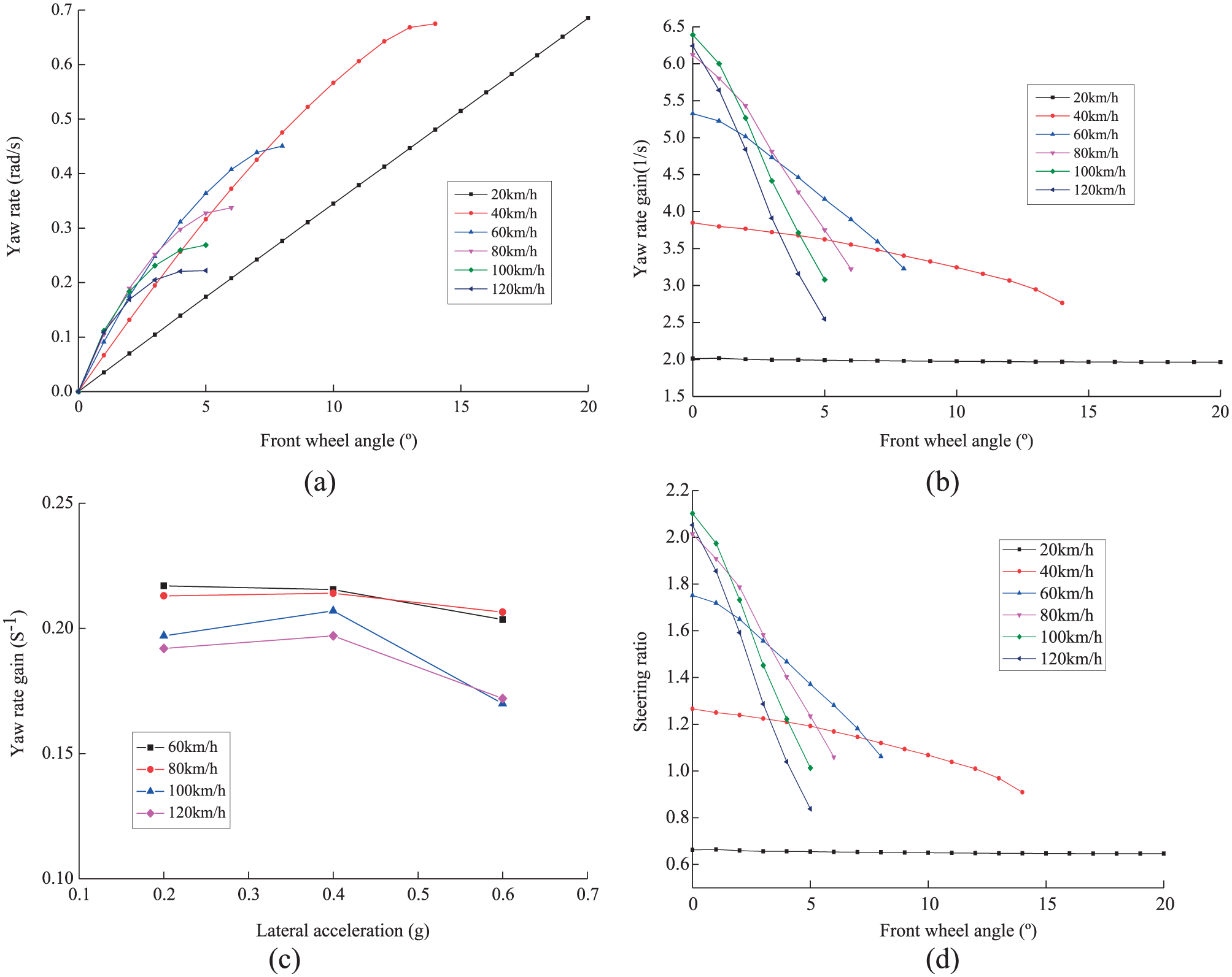
Key features of constant-yaw-rate-gain design: (a) steady-state yaw rate versus front wheel angle, (b)
A separate study revealed that for vehicles equipped with conventional steering wheel, the range of yaw rate gain Kr normally varies from 0.12 to 0.37 s−1. 19 Figure 4(c) shows the relationship between Kr and vehicle lateral acceleration at different speeds.
In order to satisfy the steering performance requirement under various vehicle speeds, in this article the yaw rate gain Kr is set to be 0.2 s−1, that is, Kr = 0.2. Assuming that the maximum steering angle of a conventional steering wheel is 380° while that of a joystick is 25°, the comparable yaw rate gain Kc for a joystick Sbw system can be calculated as
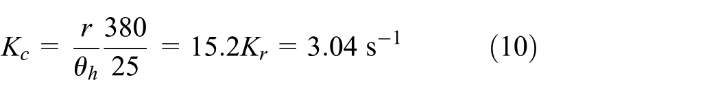
where Kc is the steady-state yaw rate gain of a joystick Sbw vehicle. In other words, Kc is the gain of vehicle steady-state yaw rate r in response to the joystick steering angle θh. Figure 4(d) shows the ideal steering ratio at each front wheel angle with Kc set to be 3.04 s−1.
Variable yaw rate gain design
In this section, another variable steering ratio design is proposed. This design is based on the constant yaw rate gain method, with extra effort devoted to improve vehicle on-centre performance by further altering the yaw rate gain. Consequently, this design is named variable yaw rate gain design. Such a design is proposed to meet the following three requirements:
When the vehicle is travelling at a low speed, the maximum front wheel angles should be reached.
When the vehicle is travelling at a middle speed, the constant yaw rate gain design proposed in section ‘Constant yaw rate gain design’ is inherited.
When the vehicle is travelling at a high speed, the on-centre steering sensitivity becomes an important index. Under such a circumstance, the lateral acceleration gain is used to design the steering ratio.
Similar to equation (7), the ratio of vehicle steady-state lateral acceleration to front wheel angle
where ay is the lateral acceleration.
The steering ratio is can then be written as

where Kay represents the steady-state lateral rate gain, that is, the gain of vehicle steady-state lateral acceleration to steering wheel angle.
The handling of vehicles’ high-speed driving with small sinusoidal steering inputs has been an interest of study.20–22 It was explained in Ryan et al. 20 that for most passenger vehicles, the value of steering sensitivity at high speed is around 1g over 100°. In order to further ensure the controllability of the vehicle at high speed, a steering sensitivity of 0.95g over 100° is used in this article to design the steering ratio at high speed. Figure 5 shows the resultant steering ratio over high-speed range.

The steering ratio design based on steady-state lateral acceleration gain at high speed.
At a middle-speed range, the steady-state yaw rate gain Kr is used to design the steering ratio. The procedure described in Kazemi and Janbakhsh 9 is followed which results in steady-state yaw rate gains as shown in Figure 6(a). In order to make a smooth transition from the yaw rate gain values determined at middle speed to those determined at high speed, the steering ratio at high speed shall be tuned. The tuning results are presented in Figure 6(b) and (c). In Figure 6(b), the yaw rate gains at middle speeds follow the solid line while those at high speeds follow the dotted line. Figure 6(c) shows the steering ratio of vehicle equipped with a conventional steering wheel as a function of vehicle speed over middle- and high-speed ranges. Assuming that the maximum steering angle of a conventional steering wheel is 380° while that of a joystick is 25°, the steering ratio of a joystick Sbw system can be determined, as shown in Figure 6(d).

Key features of variable-yaw-rate-gain design: (a) ideal steady-state yaw rate gain versus speed, (b) tuned ideal steady-state yaw rate gain versus speed, (c) steering ratio of a conventional steering wheel vehicle and (d) steering ratio of a joystick Sbw vehicle.
Simulation and experiments
Computer simulation
In this section, computer simulation of steering performances of a conventional vehicle and a joystick Sbw vehicle is presented and discussed for the purpose of validating the four variable steering ratio design methods described in the previous section. Here, the conventional vehicle is equipped with a steering wheel and the steering ratio is kept to be constant. On the other hand, the joystick Sbw vehicle is equipped with a joystick and the proposed variable steering ratio designs.
In the first place, simulation of a driver single sinusoid steering input test at a slow vehicle speed is performed. The aim of this simulation is to investigate a driver’s burden. The period of the sinusoid steering input is set to be 50 s while vehicle speed is set as 10 km/h. Simulation results are displayed in Figure 7. Specifically, Figure 7(a) shows the time histories of vehicle front wheel angle. Figure 7(b) shows the time histories of driver steering input which should represent the steering wheel angle in a conventional vehicle but the joystick steering angle in a joystick Sbw vehicle. Figure 7(c) and (d), respectively, show the time histories of vehicle yaw rate and lateral acceleration. It can be seen from Figure 7(a) that the constant steering ratio and the four joystick steering ratio design methods give quite similar vehicle front wheel angle amplitudes. Consequently, the resultant vehicle raw rate and lateral acceleration responses as shown in Figure 7(c) and (d) are quite similar. However, it can be found clearly from Figure 7(b) that the joystick steering angle amplitudes which are around 14° are far smaller than the steering wheel angle which is around 28°. This indicates that the joystick Sbw system could help reduce the burden of a driver.
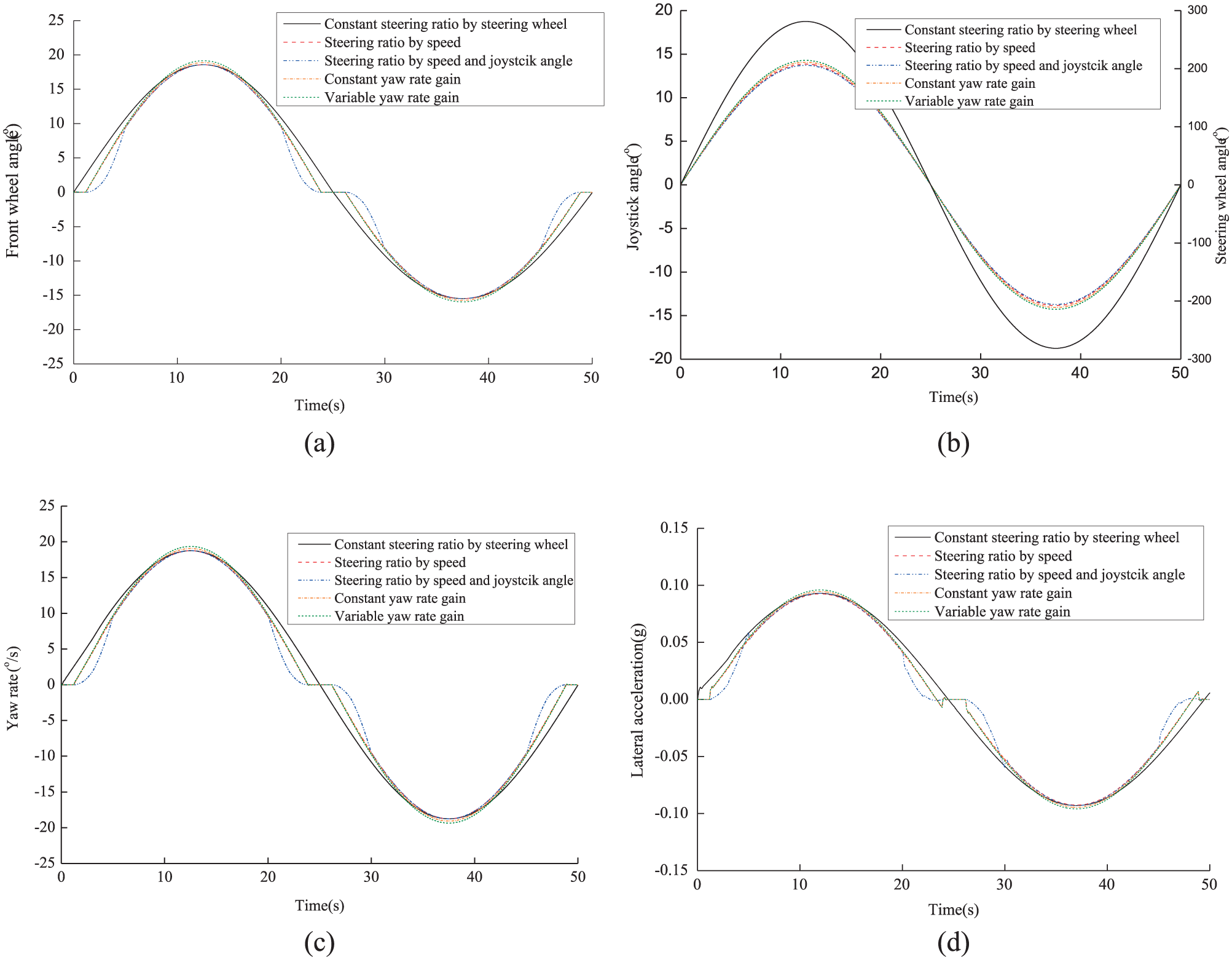
Simulation results of single sinusoid driver steering input test: (a) vehicle front wheel angle time history, (b) steering wheel angle/joystick angle time history, (c) vehicle yaw rate time history and (d) vehicle lateral acceleration time history.
Second, simulation of a driver step angle steering input test is carried out at a middle vehicle speed. The steady-state value of the front wheel angle is set to be 4° while vehicle speed is set as 40 km/h. Simulation results are displayed in Figure 8 where subfigures (a), (b), (c) and (d), respectively, show the time histories of vehicle front wheel angle, driver steering input, vehicle yaw rate and lateral acceleration. It can been seen from Figure 8(a), (c) and (d) that the constant steering ratio and the four joystick steering ratio design methods yield identical steady-state front wheel angles which, in turn, give identical steady-state yaw rates and lateral accelerations. However, as shown in Figure 8(b), the steady-state value of the steering wheel angle is 75° which is much larger than those resulting from the four variable joystick steering ratio designs. Moreover, it can be seen that the constant yaw rate gain design results in smaller joystick steering angle amplitude.
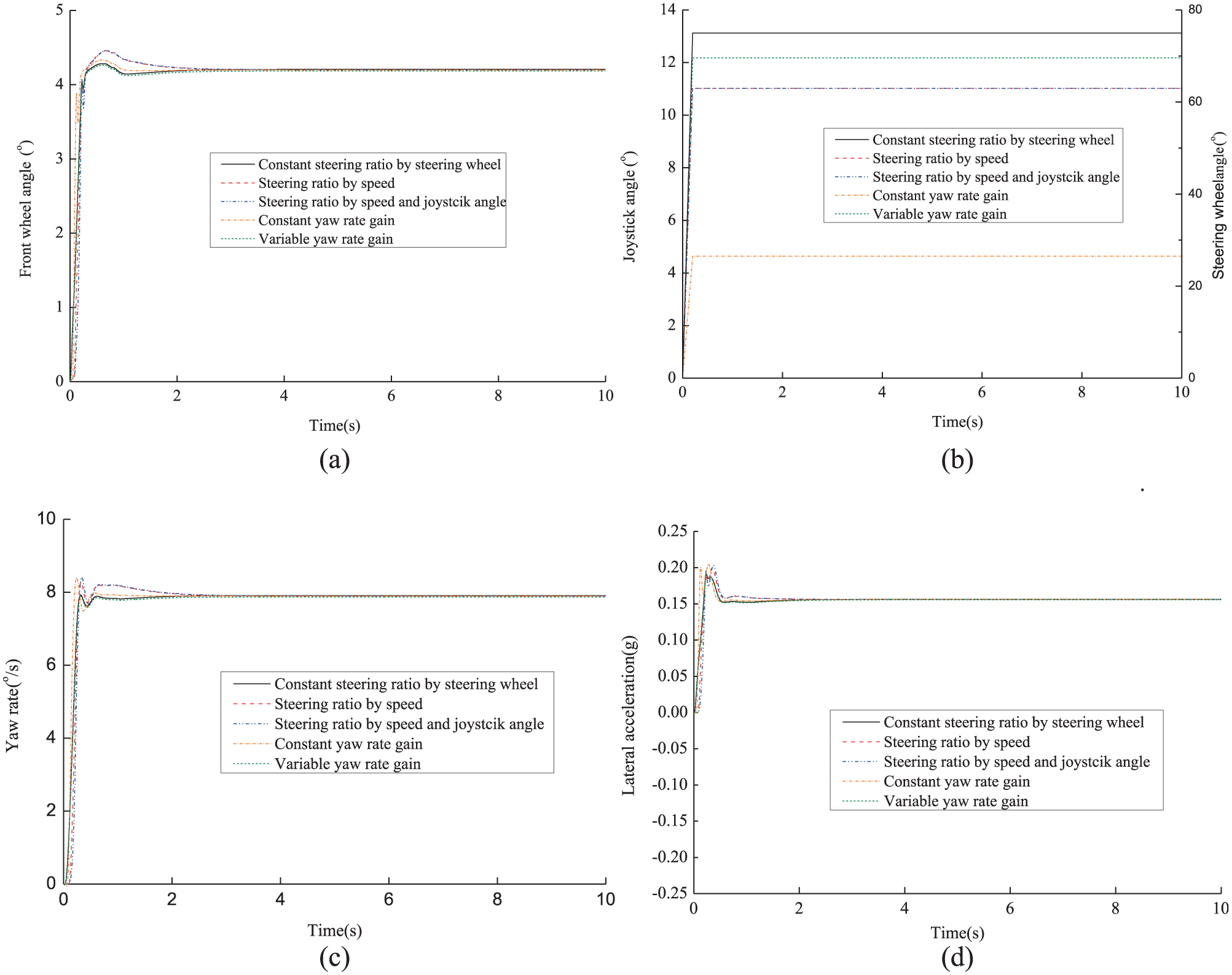
Simulation results of step angle driver steering input test: (a) vehicle front wheel angle time history, (b) steering wheel angle/joystick angle time history, (c) vehicle yaw rate time history and (d) vehicle lateral acceleration time history.
Third, simulation of an on-centre steering input test is carried out at a high vehicle speed. The aim of this test is to investigate vehicle handling in highway driving where a driver’s steering angle input is generally small. In this test, the driver is set to exert a continuous sinusoidal steering input of 0.2 Hz at a vehicle speed of 100 km/h. Simulation results are displayed in Figure 9 where subfigures (a), (b), (c) and (d), respectively, show the time histories of vehicle front wheel angle, driver steering input, vehicle yaw rate and lateral acceleration. It can be seen from Figure 9(a) that the constant steering ratio and the four joystick steering ratio design algorithms all give similar front wheel angle time histories. Consequently, the resultant vehicle yaw rate and lateral acceleration responses are in similar manner, as suggested by Figure 9(c) and (d). It can be seen from Figure 9(b) that the amplitude of the joystick steering angle resulting from the constant yaw rate gain–based steering ratio design is less than 5°, which is too sensitive from the perspective of a driver. This would cause the driver to put in too much effort to control the vehicle. Such a problem is overcome by adopting the variable yaw rate gain–based steering ratio design.
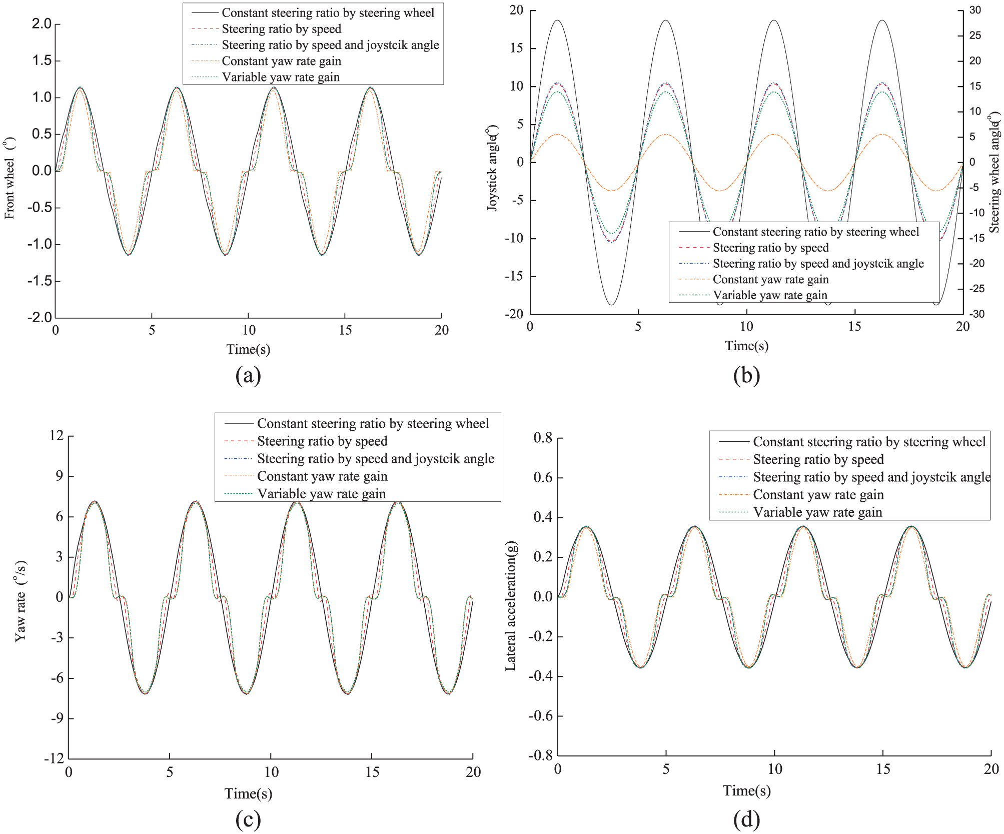
Simulation results of continuous sinusoid driver steering input test: (a) vehicle front wheel angle time history, (b) steering wheel angle/joystick angle time history, (c) vehicle yaw rate time history and (d) vehicle lateral acceleration time history.
According to the three simulation tests described above, it can be seen that all the four joystick steering ratio design algorithms result in far smaller amount of driver steering action than a conventional vehicle equipped with a steering wheel. In addition, it can be found that the variable yaw rate gain–based design is advantageous.
Driving simulator experiment
Eight test subjects, ageing from 25 to 36 years, with an average driving experience of approximately 5 years, were invited to participate in an experiment using a fixed-base driving simulator to evaluate the performance of the variable yaw rate steering ratio design proposed in section ‘Variable yaw rate gain design’.
The configuration of the driving simulator is schematically shown in Figure 10(a). The driver interface of the simulator is shown in Figure 10(b) where it can be seen that apart from the joystick which is mounted at the right-hand side of the driver seat, all the remaining parts are quite similar to those equipped in a real passenger car, including the conventional steering wheel.

Fixed-base driving simulator: (a) configuration and (b) driver interface.
Three test scenarios are designed for the experiment:
Test on an 8-shaped track at a low speed of 10 ± 2 km/h.
Test on a country road at a middle speed which can vary from 30 to 80 km/h according to test subjects’ own preference.
Test on a straight road on which a double-lane change route was marked by cones at a high speed of 100 km/h.
All these three test scenarios are displayed to test subjects through the screen of the driving simulator. In the experiment, each test subject is required to use both the steering wheel and the joystick in the driving simulator to control the vehicle. During driving, each test subject is instructed to focus on perceiving the handling and directional responses of the vehicle. On finishing a test scenario, the test subject is required to give a rating according to his perception. The rating scale described in SAE J1441 (Subjective Rating Scale for Vehicle Handling) is used. The rating results including both individual ratings and averaged ratings from the eight test subjects are presented in Table 1.
Test subjective rating results.
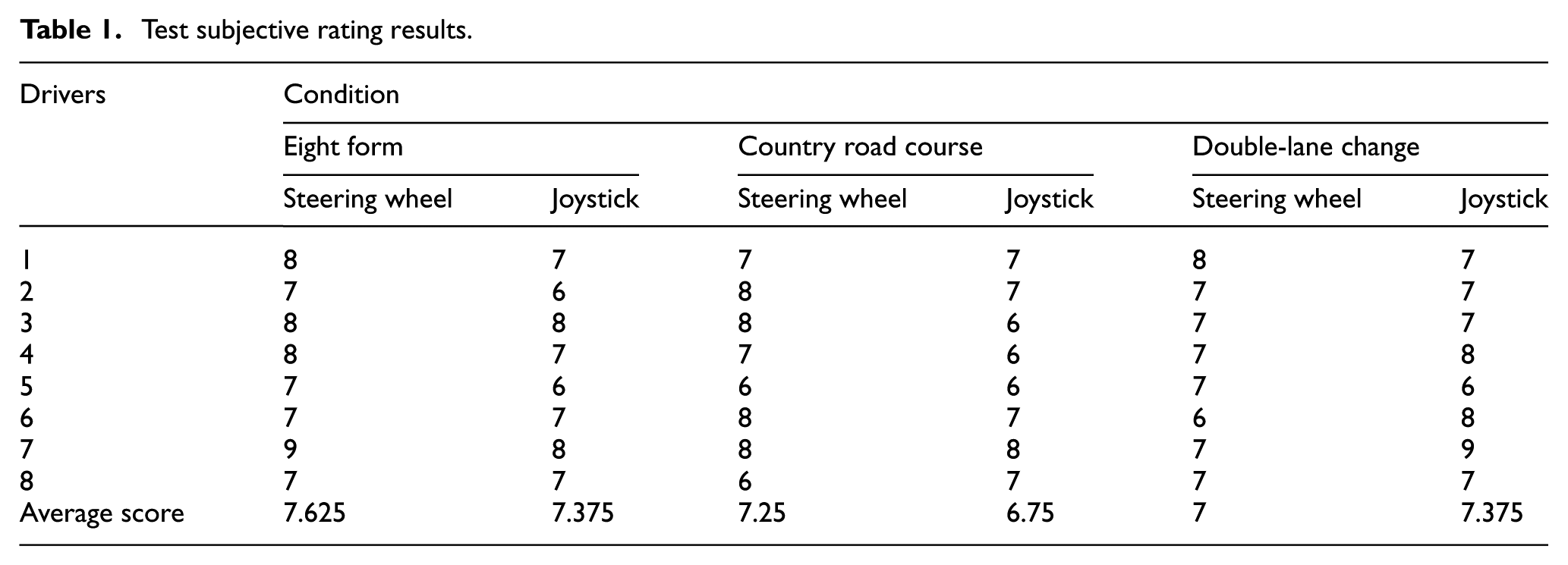
As it can be seen from Table 1, the ratings for the joystick are slightly lower than those for the conventional steering wheel for the 8-shaped track and country road test scenarios. This implies that the joystick is slightly less preferable than a conventional steering wheel; however, it is still acceptable to all the test subjects. On the other hand, it can be found that for the double-lane change scenario, seven test subjects rated the joystick at least not worse than the steering wheel, and one of them even gives the joystick a better rating by 2 scales than the steering wheel. All these facts resulted in that the average rating for the joystick is slightly higher than that for the steering wheel. This indicates that the joystick is more favourable in the double-lane change scenario. Following the ratings, interviews were carried out to all the eight test subjects and it was found that most of the test subjects thought the joystick could help them control the vehicle to negotiate the coned double-lane change track more easily than the conventional steering wheel, although they still found a bit tricky to use the joystick to control the vehicle in normal driving conditions. In summary, the subject ratings and the interviews revealed that the variable yaw rate steering ratio design for the joystick Sbw system has the potential to replace the conventional steering wheel while similar vehicle handling can be maintained.
Experimental measurements of the 8-shaped track test are shown in Figure 11. Figure 11(a) shows the time histories of vehicle yaw rate under both joystick and steering wheel cases. Figure 11(b) shows the time histories of vehicle lateral acceleration. Figure 11(c) shows the bird view of the test track. Figure 11(d) shows the vehicle trajectories. It can be seen from Figure 11(a) and (b) that the joystick control generally leads to faster and more direct vehicle responses than the steering wheel control. This is thought to be due to the fact that it requires a driver far less arm movement to use the joystick to fulfil a manoeuvre. It can be seen from Figure 11(d) that the vehicle trajectory resulting from the joystick control is practically identical to that resulting from the steering wheel control. This implies that the test subjects were able to use the joystick to control the vehicle to follow the test track, which coincides with their ratings for the joystick as comparably acceptable as displayed in Table 1.
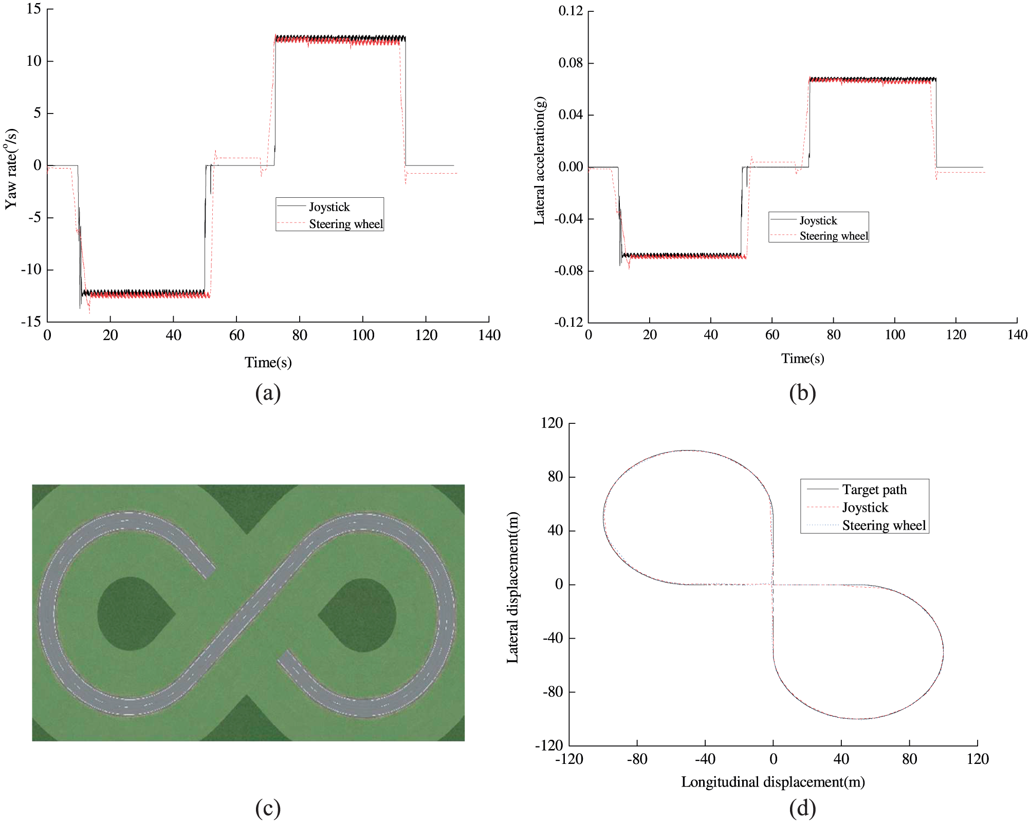
Experimental measurements of 8-shaped track test: (a) yaw rate time histories, (b) lateral acceleration time histories, (c) track of 8-shaped test and (d) vehicle trajectories.
Experimental data of the country road test are shown in Figure 12 where Figure 12(a) and (b) shows the time histories of yaw rate and lateral acceleration, respectively, Figure 12(c) shows a typical part of the test road and Figure 12(d) shows vehicle trajectories. It can be seen from Figure 12(a) and (b) that the time histories from the joystick control involve slightly more fluctuations and inconsistency. This is believed to be due to the fact that the test subjects are less skilful in using the joystick than the conventional steering wheel. Figure 12(d) reveals that the test subjects could use the joystick to drive the vehicle as he or she uses the conventional steering wheel.

Experimental measurements of country road test: (a) yaw rate time histories, (b) lateral acceleration time histories, (c) part of country road and (d) vehicle trajectories.
Experimental data of the double-lane change test are shown in Figure 13 where the four subfigures (a), (b), (c) and (d) are arranged in the same manner as those in Figures 11 and 12. Similar to what were observed in Figure 11, it can be seen from Figure 13(a) and (b) that the joystick control results in larger vehicle response amplitudes during the first lane change while smaller amplitudes during the second lane change. This indicates that using the joystick, test subjects were capable of making the vehicle to respond to his or her lane change initiative in a more direct manner and to return the original lane with less steering control effort. It can also be found from Figure 13(d) that during the second lane change, that is, the return to the original lane, the joystick control leads to very little vehicle lateral displacement overshoot while obvious vehicle lateral movement can be observed for the steering wheel control. All these observations are consistent with the subjective ratings presented in Table 1 where most test subjects gave higher ratings to the joystick control than the steering wheel.

Experimental measurements of double-lane change test: (a) yaw rate time histories, (b) lateral acceleration time histories, (c) track of double-lane change test and (d) vehicle trajectories.
The subjective ratings and objective experimental measurements imply that in comparison to the steering wheel control, the joystick steering with the variable yaw rate gain design provides an opportunity to improve vehicle handling and controllability, especially for high-speed manoeuvres.
Conclusion
In this article, some typical steering ratio design methods were analysed in Sbw system, and a joystick steering system dynamic model was built based on bilateral control scheme. An effect of variable steering ratio design method and steering characteristics were applied on joystick for Sbw vehicle. Four kinds of design methods were presented to study steering characteristics of joystick system. On this basis, a novel variable steering ratio design method is proposed for variable yaw rate gain control of joystick system that could be utilized to substitute the conventional steering wheel. The variable yaw rate gain steering ratio was verified that could effectively achieve a satisfactory steering performance in three different computer simulation and experimental conditions. The driver simulator was also used to validate the variable yaw rate steering ratio of joystick system. Eight drivers were selected to finish three kinds of subjective test conditions and the results demonstrated the effectiveness. The proposed variable steering ratio design method is believed to provide effective vehicle steering performance.
Footnotes
Handling Editor: ZW Zhong
Declaration of conflicting interests
The author(s) declared no potential conflicts of interest with respect to the research, authorship, and/or publication of this article.
Funding
The author(s) disclosed receipt of the following financial support for the research, authorship, and/or publication of this article: This work was partially supported by National Natural Science Foundation of China (no. 51575223) and Foundation of State Key Laboratory of Automotive Simulation and Control in Jilin University.