
Abstract
This research aims to establish a finite element analysis model of the polishing process of silicon carbide (SiC) ceramics and to study the change processes of the polishing force, which can lead to stress and strain inside SiC under different processing parameters. This will provide a more reasonable scheme for the actual processing of brittle materials. The simulation results indicate that the interference of the impact force can be effectively reduced by changing the abrasive particle size and polishing depth, and that the polishing force can be changed in a relatively stable range to improve the surface quality of the brittle material. Subsequently, polishing experiments are carried out in accordance with the computer-controlled precision polishing process. The experimental results reveal that the abrasive particle size and polishing depth are the most relevant factors for the minimization of surface roughness. In addition, the influence trends of surface quality of the experimental results at different process parameters match well with the simulation results. These research results are meaningful and helpful for the selection of reasonable polishing parameters in order to obtain good surface quality in the SiC polishing process.
Keywords
Introduction
Engineering ceramics have been widely used in aerospace, precision machinery, and inertial guidance due to their superior properties, such as high hardness and strength at elevated temperatures, chemical stability, high wear resistance, and low friction.1–3 However, their high brittleness and low fracture toughness make ceramic materials prone to generate surface/subsurface micro-cracks, material powder, fuzzy surfaces, phase transformation, and residual stresses, which influence the adoption of surface integrity and their fatigue properties.4,5 The topography and integrity of silicon carbide (SiC) ceramic are of immense importance, particularly in safety-critical applications involving aerospace components. Considering the material properties of SiC, it can be seen that it is challenging for the ground micro-structured surface quality to meet the requirements of applications. Therefore, the use of a post-fabrication polishing process has been proposed. However, surface defects still appear in SiC workpieces during the polishing process where diamond grains present in tools act as indenters. 6 Although the precision of many advanced methods is very high, the cost of these methods is also high, and these methods are therefore not suitable for mass production of SiC materials.7,8 Computer-controlled precision polishing may be used for industrial production because of its low cost and high efficiency. However, the polishing of SiC is still challenging in terms of surface quality.
Due to the importance of processing parameters, many studies have been conducted on the relationship between the surface quality and processing parameters. Barahimi and Farahnakian 9 carried out a grinding experiment of BK7 optical glass to investigate the influences of grinding parameters on the surface roughness (SR), and the experimental results indicated that the process parameters (feed rate, depth of cut, and cutting speed) affected the SR significantly. Liao et al. 10 used Taguchi’s method and experimental methods and found that the platen speeds, carrier speeds, and head-down forces significantly affected the removal rate and non-uniformity of the surface profiles for chemical mechanical polishing. Chen et al. 11 developed a new surface/subsurface damage model considering wheel vibration, and by the derivation of the effect of wheel speed and other grinding process parameters on the SR and subsurface damage, they analyzed the effect of grinding depth, feed rate, wheel speed, and other grinding process parameters on the SR and subsurface damage. Yao et al. 12 carried out experiments to determine the influence of high-speed milling on the surface integrity and fatigue behavior, and the results showed that the milling speed and the feed per tooth had a significant effect on the SR. Demir et al. 13 carried out grinding tests using different grinding wheels of different grains, and the results showed that grain size significantly affected the grinding forces and SR values. Hecker and Liang 14 predicted the arithmetic mean SR based on a probabilistic undeformed chip thickness model and verified using experimental data from cylindrical grinding. Axinte et al. 15 studied the influence of three engineered grinding grit shapes on different materials and experimentally verified that in the grinding of brittle materials, circular base frustum grit led to a greater specific cutting force than the grits with square shape and triangular shape. Esmaeilzare et al. 16 used a diamond wheel to grind the Zerodur® glass-ceramic, investigated the influence of the grinding parameters on the SR, and developed a statistical model to predict the SR. Agarwal and Rao 17 studied the impact of the grinding state on the damage surface/subsurface by analyzing the grinding characteristics, surface integrity, and material removal mechanisms when grinding the surface of SiC with a diamond wheel. Li et al. 18 established a grinding force model of ultrasonic vibration assisted grinding (UVAG) and carried out the single-factor experiment which illustrated that the grinding force increased with the increase in the grinding depth, feed rate, and amplitude, while it decreased with the increase in the spindle speed; the contrast experiment showed that UVAG was beneficial for improving the surface quality.
As mentioned above, many researchers have carried out theoretical and experimental studies on the mechanism and influence factors of SiC materials processing; however, these experiments still have some shortcomings, including the generally low speed and certain difficulty of specific experimental implementation and measurement of physical quantities.
Currently, finite element analysis model (FEM) simulations have also been widely used to model the machining process of brittle materials, and it is an important method to study the mechanism of machining process.19–21 For example, Wang et al. 22 used FEM simulations to study the effects of wheel speed, grinding depth, apex angle of abrasive grain, and workpiece feed rate on the material removal rate and grinding force in brittle material grinding. Li et al. 23 investigated the brittle–ductile transition of ceramics in high-speed grinding by the simulation of single-grit scratch test and achieved better surface quality and machining efficiency. Nam et al. 24 proposed a numerical cutting model that represented the cutting behavior of brittle materials using the smooth particle hydrodynamics (SPH) method and simulated crack propagation using the stress distribution and damage parameters of the workpiece. Hadavi et al. 25 utilized an element-free Galerkin (EFG) formulation and the SPH technique to simulate the impact and fracture of SiC particles on an aluminum alloy target. Feng et al. 26 developed a cohesive zone model (CZM)-based finite element model to predict the grinding force in micro-grinding of ceramic materials. Chen et al. 27 investigated the distribution and scattering of surface residual stress in ultra-high-speed grinding using a mathematical statistical method. Zhu et al. 28 conducted a single-grit high-speed SiC grinding simulation, and the simulation results indicated that the wheel speed became insensitive to the workpiece surface morphology in the ductile regime, whereas in the brittle regime, the workpiece surface integrity depended on the wheel speed. Liu et al. 29 investigated the individual crack generation and propagation in SiC indentation and engagement under different wheel surface speeds by single-grit simulation, and the results showed that the high-speed grinding could achieve high material removal rates with better surface and subsurface quality in SiC machining.
Many efforts have been made to investigate the material removal and surface machining mechanism in the polishing process. However, the studies of the surface quality in the polishing process of SiC considering the dynamic parameters by means of simulation and experiment have been rare. The primary focus of this work is to investigate the influence of the various machining parameters on the machined surface quality. Furthermore, an approach based on single-grit simulation is employed in the present work so that the dependences of the surface quality on the processing parameters are identified and explained. In this article, a new model for polishing simulations is employed to investigate the contact force between the abrasive grains and the specimen. Then, related experiments are carried out to study the influence of the machining parameters on the surface quality of the workpiece. These powerful experimental results can provide a better understanding of machining parameters and will be beneficial for the optimization of polishing parameters to obtain perfect surface quality in SiC polishing.
Numerical simulation
Simulation model
As shown in Figure 1, the actual surface obtained by polishing is the result of the interaction between the abrasive particles and the workpiece. Because of the different abrasive grain shapes, elastic state, and cutting edge, each particle has different working states. For the abrasive particle with the lower cutting edge height and the larger cutting edge radius, the polishing process of the workpiece is regarded as the indentation process of the spherical indenter. In this study, the complex polishing process is simplified to the single-particle scratch process.
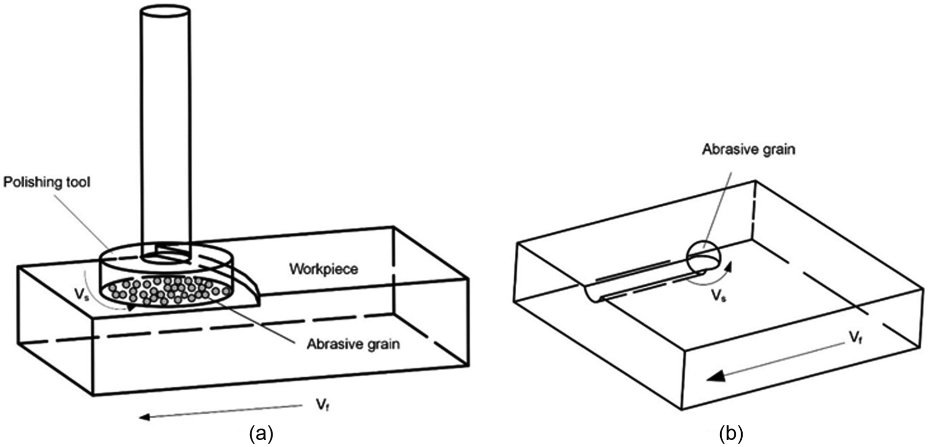
Simplified sketch of polishing process: (a) polishing tool and (b) single abrasive grain.
Simulation method
The selection and establishment of a material constitutive model is directly related to the rationality and reliability of the simulation results. In this study, a brittle cracking model and the failure criteria of brittle shear and brittle failure are adopted because SiC is a brittle material. 30 The interface constitutive relation is divided into three stages: elastic-plastic deformation stage, plowing stage, and brittle removal stage (linear softening stage). The failure evolving regulation can be expressed by the energy method. The stress–strain response is illustrated in Figure 2. εi is the cracking strain, and εf is the maximum strain. The constitutive relation for the interface is given by equation (1)

where D is the shear modulus, E0 is the initial diagonal stiffness matrix of the crack model, K is the stiffness of the material, and F is the load.
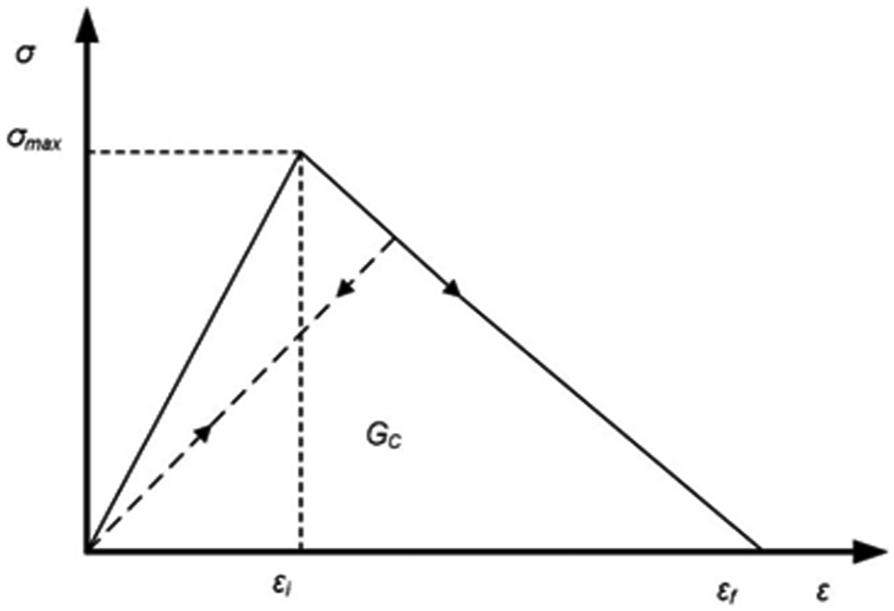
The stress–strain response.
We select quads damage as the damage failure criterion of the cohesive element: 31 when the square of the nominal stress ratio in each direction is equal to 1, the damage begins, as shown below

where
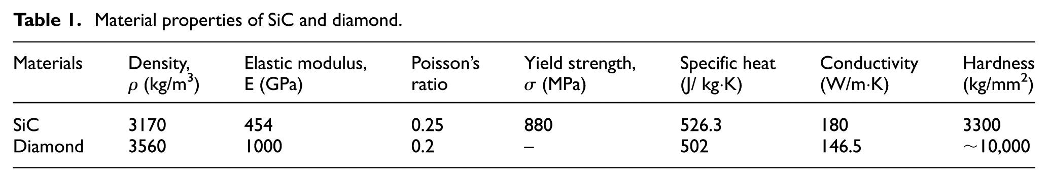
To further explore the effects of process parameters on the force and surface quality during polishing, FEM simulations are carried out using the ABAQUS finite element software. 32 A finite element model (60 μm × 15 μm × 20 μm) is used to simulate the polishing processing with a single abrasive grain in this study, as shown in Figure 3. In the simulation model, SiC ceramic is chosen as the specimen. The material parameters based on the brittle cracking constitutive model are shown in Table 1. The hardness and elastic modulus of the single diamond abrasive are higher than those of the workpiece. Therefore, the abrasive grit is assumed to be a rigid body during the simulation. The element type C3D8R is used to divide the workpiece. For the accuracy of simulation, the element is divided very densely in the cutting path but has low density in the other regions. The dense mesh area is larger than the contact area between the abrasive grains and the workpiece, preventing the simulation errors caused by the contact between the abrasive particles and the larger grit. The friction coefficient between the workpiece and the abrasive particles is 0.3. In dynamic analysis, a small number of units with small size control the steady time increment. To reduce the computational cost, ABAQUS often uses the method of mass scaling. The scaling factor is set to 300.

Polishing simulation model of single grain.
Material properties of SiC and diamond.
This article focuses on the effect of the four processing parameters, namely, the polishing depth ap, rotation speed Vs, feed rate Vf, and abrasive grain diameter D, on the surface quality and machining mechanism of SiC in the polishing process. The simulation results provide more reasonable machining conditions for the actual processing of brittle materials. The machining parameters used in the simulation process are shown in Table 2.
Machining parameters of simulation.

Simulation results and discussion
Analysis of abrasive grain-polishing process
During the simulation of silicon ceramic polishing with a single diamond grain, the area of the deformation and stress of the workpiece will change with the polishing movement of the abrasive grains. The deformation and stress plots of the workpiece are shown in Figure 4 for the polishing depth ap = 2 μm, rotation speed Vs = 1000 r/min, feed rate Vf = 2500 mm/s, and abrasive grain diameter D = 12 μm. As shown in Figure 4(a), when the abrasive grain begins to contact the workpiece surface, the elastic–plastic deformation occurs accordingly. A part of the abrasive grain exerts a certain pressure on the workpiece, and the deformation is small. The maximum stress is 247 GPa. As the abrasive particles cut the workpiece surface gradually, the workpiece surface stacks bulge in the direction of the cutting speed and two sides of the abrasive grain, and the grain edge scratches the workpiece surface as shown in Figure 4(b). The workpiece in this area has a large deformation to advance into the plastic deformation and plowing stage. The maximum stress increases rapidly to 395.6 GPa. As shown in Figure 4(c), with the further cutting of the abrasive grain, the strip stacks are formed by the extrusion of flaky bulges in front of the abrasive grain, and then break away from the workpiece. The stress decreases temporarily. Figure 4(b) and (c) show the transition of the material removal from the ductile to brittle–ductile mode. Material flaking results in decrease in stress. Therefore, the stress reaches the strength limit of the material, as shown in Figure 4(b). As shown in Figure 4(d), the abrasive chips break away from the workpiece surface completely. The surface ahead of the abrasive grain is then squeezed again. The material removal once again enters the ductile stage. The raised material in the plow area gradually fills the space between the machined surface and the abrasive grain. Abrasive grain rotation generates shear stress, and the strip winding abrasive chips occur. The maximum stress increases to 282 GPa. As the abrasive grain continues to cut, the strip abrasive chips break away from the workpiece surface by extrusion and shear stress, as shown in Figure 4(e). The stress decreases to 257 GPa. As described above, the stress repeatedly fluctuates within a certain range to complete the removal of surface materials.

Polishing process of brittle material: (a) t = 0.67 × 10⁻⁶ s, (b) t = 2.01 × 10⁻⁶ s, (c) t = 6.70 × 10⁻⁶ s, (d) t = 1.14 × 10⁻⁵ s, and (e) t = 1.34 × 10⁻⁵ s.
Effects of polishing depth on polishing force and surface quality
The cutting depth plays an important role in the machining process of brittle materials, and in this simulation, the polishing depth ap is taken as 2, 2.6, and 3 μm. The effects of different polishing depths on the reaction force are shown in Figure 5 with the rotation speed Vs = 1000 r/min, feed rate Vf = 2000 mm/s, and abrasive grain diameter D = 12 μm. Examination of Figure 5 shows that the force increased sharply in a short period of time and then gradually decreased to a stable value with fluctuations within a certain range. This is due to the abrasive grains contacting the workpiece at a certain speed, which will impact the workpiece. Moreover, the smaller polishing depth causes a smaller change rate of the impact force on the workpiece surface, but the time of the force recovery is approximately 0.000005 s. When the polishing depth is 2 μm, the average force is 0.42718 N after 0.000005 s, and the force peak is 0.56975 N, exceeding the average value by 33.375%. The standard deviation (fluctuation range of contact force) is 0.042708 N. When the polishing depth is 2.6 μm, the average force is 0.36257 N after 0.000005 s, and the peak force is 0.56086 N, exceeding the average value by 54.690%. The standard deviation is 0.044185 N. When the polishing depth is 3 μm, the average force is 0.2891 N after 0.000005 s, and the peak force is 0.45671 N, exceeding the average value by 57.938%. The standard deviation is 0.050005 N. Considered together with the force curves, the above data show that the smaller cutting depth causes a larger force on the surface of the workpiece and a smaller fluctuation range of the contact force. It can be seen that the smaller polishing depth can reduce the vibration of the polishing force and improve the quality of the machined surface.
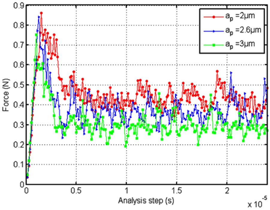
Effect of ap on contact force for D = 12 μm, Vf = 2000 mm/s, and Vs = 1000 r/min.
Figure 6(a)–(c) shows the chip shapes and stress distribution at polishing depths of 2, 2.6, and 3 μm, respectively. Examination of Figure 6(a) clearly shows that the abrasive chips are flaky and short-banded, the size is smaller, and the stress nephogram shows that the residual stress distribution is uniform and symmetrical. When the polishing depth increases to 2.6 μm, the abrasive chips are long-banded, and the size is larger, as shown in Figure 6(b). At the same time, long-banded abrasive chips form a spiral shape because of the influence of the abrasive particle speed. However, this causes the local stress to be too high, the stress distribution to be non-uniform, and the surface quality of the brittle materials to be affected. With the further increase in the depth, long-banded abrasive chips randomly twine together, which can enlarge the influence of the stress distribution. As shown in Figure 6(c), the stress of the workpiece surface is relatively large, and the brittle material fracture extends to the unprocessed surface, severely affecting the quality of the machined surface.
Effect of ap on polishing debris shapes for D = 12 μm, Vf = 2000 mm/s, and Vs = 1000 r/min: (a) ap = 2 µm, (b) ap = 2.6 µm, and (c) ap = 3 µm.
Effects of rotation speed on polishing force and surface quality
The polishing force curves of the machined workpiece at various rotation speeds (Vs = 600, 800, 1000, or 1500 r/min) are illustrated in Figure 7 for polishing depth ap = 2 μm, polishing speed Vf = 2000 mm/s, and abrasive grain diameter D = 12 μm. It can be seen that the contact force goes through three stages: mutation, recovery, and vibration. The four curves of the mutation phase are coincident, and the change in the rotation speeds has little effect on the contact force. In the stage of force vibration, for Vs = 600 r/min, the average force is 0.742750 N and the standard deviation (fluctuation range of contact force) is 0.081519 N; for Vs = 800 r/min, the average force is 0.704404 N and the standard deviation is 0.079914 N; for Vs = 1000 r/min, the average force is 0.633696 N and the standard deviation is 0.070085 N; for Vs = 1500 r/min, the average force is 0.677809 N and the standard deviation is 0.071377 N. This shows that the average value of the force and the force fluctuations decrease with the increasing rotation speed from 600 to 1000 r/min. However, when Vs = 1500 r/min, the fluctuation range of the contact force will increase slightly. This is because the material to be removed on the front side of the abrasive grains will fly out at a high speed if the rotation speed is too high, resulting in a greater impact on the workpiece; flying out of the abrasive chips impacts the workpiece surface and will cause a sudden change in the contact force affecting the smoothness of the polishing process.

Effect of Vs on contact force for D = 12 μm, Vf = 2000 mm/s, and ap = 2 μm.
Effects of abrasive grain diameter on polishing force and surface quality
The contact force is shown in Figure 8 when the abrasive grain sizes are changed. Here, three abrasive grain diameters (D = 6, 9, or 12 μm) are applied to compare the simulation results for the polishing depth ap =2 μm, rotation speed Vs = 1000 r/min, and polishing speed Vf = 2000 mm/s. As seen from Figure 8, the impact of the instantaneous increasing in the contact force is inevitable in the beginning of the processing. The effect of different particle sizes on the surface is different in the processing of brittle materials. When the abrasive grain diameter is 6 μm, the impact force is very small and the time to restore the stability is the shortest. The fluctuation range of the contact force is much smaller than that for the other two groups, which is beneficial for the improvement of the surface quality of the brittle material. When the size increases, the impact is more obvious, and the force fluctuation increases. Compared to the polishing depth and rotation speed, abrasive size shows greater influence on the polishing force and surface quality.

Effect of abrasive grain diameter on contact force for Vf = 2000 mm/s, ap = 2 μm, and Vs = 1000 r/min.
Effects of polishing speed on cutting force and surface quality
Figure 9 shows the contact force obtained for three different feed rates (Vf = 1500 mm/s, 2000 mm/s, 2500 mm/s, or 3000 mm/s). It is clear that when the feed rate is increased from 1500 to 2500 mm/s, the average force increases from 0.441878 to 0.533709 N and the standard deviation (fluctuation range of the contact force) increases from 0.047949 to 0.058577 N. However, when Vf = 3000 mm/s, the average force is 0.505956 N and the standard deviation is 0.055613; the fluctuation range of the contact force will decrease slightly. This is because if the feed rate is too high, the contact time between the abrasive grain and the workpiece is very short, and the material removal effect is not obvious; therefore, the contact force and force fluctuation decrease slightly. However, it is difficult to control the high feed rate. In the above four conditions, contact force fluctuation also occurs, and the fluctuation changes gradually with the workpiece feed rate compared to the other processing parameters. Although increasing polishing speeds can slow the fluctuation in the contact force, the fluctuation cannot be avoided.
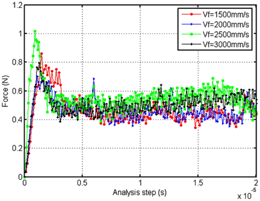
Effect of Vf on contact force for D = 12 μm, ap = 2 μm, and Vs = 1000 r/min.
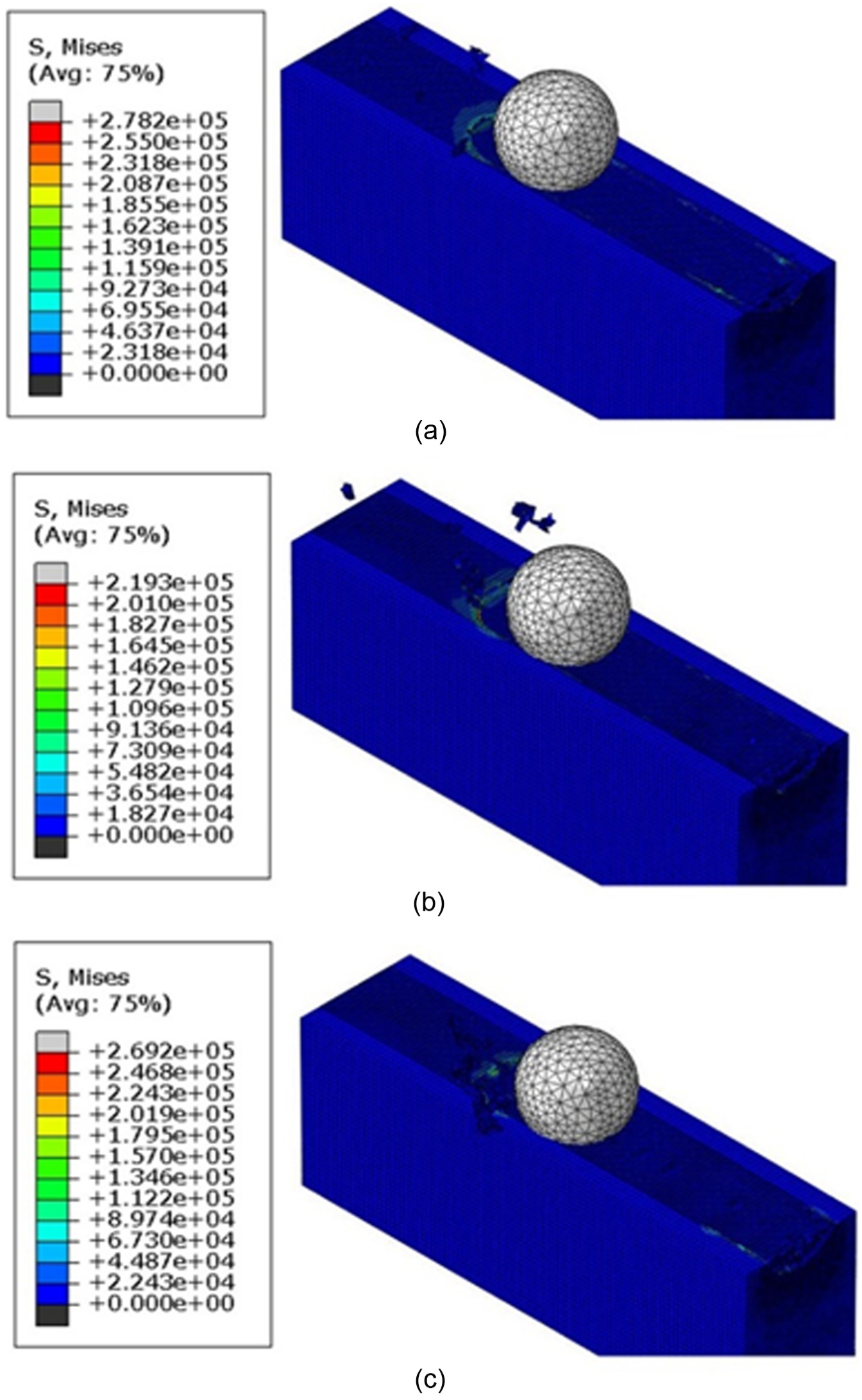
The chip shapes and stress distributions for the feed rates of 2000 mm/s, 2500 mm/s, and 3000 mm/s are shown in Figure 10. When the feed rate is 2000 mm/s, the stress distribution on the surface is uniform and symmetrical, and the distribution area is small. With the increase in Vf from 2000 to 3000 mm/s, the removal abrasive chips are quickly pushed to form a stack due to the excessive feed rate. In the abrasive scratching of the material surface, the stack will produce friction and collision with the workpiece surface, resulting in a non-uniform stress distribution on the surface, and even leading to local stress that is too large (black line in Figure 10(c). The effect of the workpiece feed rate on the material removal is not distinct, and a smaller abrasive chip size is also able to achieve a smaller material removal volume.

Effect of Vf on polishing debris shapes for D = 12 μm, ap = 2 μm, and Vs = 1000 r/min: (a) Vf = 2000 mm/s, (b) Vf = 2500 mm/s, and (c) Vf = 3000 mm/s.
Experimental work
Experimental methods
The polishing setup of the experiments is shown in Figure 11. A series of spot polishing experiments have been conducted on an in-house five-axis linkage polishing machine. A cylindrical wool-felt polishing tool, with a diameter (Φ) of 10 mm is used. Polishing paste with different sizes of diamond grits is used. The samples used for this study are the reaction-bonded SiC ceramics (Φ = 50 mm × 2 mm). Prior to the experiments, all ground surfaces will be roughly polished with the W40 and W20 grit diamond polishing paste using the following process parameters: rotation speed Vs = 1500 r/min, feed rate Vf = 20 mm/s, and polishing depth ap = 5 μm. The polishing time is set to 30 min. The polishing parameters, including the polishing depth, rotation speed, feed rate, and abrasive size, are adopted to investigate their influence on the SR and surface topography. The experimental parameters are listed in Table 3. The four tests are denoted as test 1 (Vs, Vf, and grain grit are constant, changing ap), test 2 (ap, Vf, and grain grit are constant, changing Vs), test 3 (ap, Vs, and Vf are constant, changing abrasive size), and test 4 (ap, Vs, and abrasive size are constant, changing Vf) and are used to study the effect on surface quality in polishing process by single-factor testing.

Experimental setup.
Machining parameters.

After completion of polishing experiments, surface morphology of the SiC ceramic before and after polishing should be given by scanning electron microscope (SEM) as shown in Figure 12. The three-dimensional (3D) surface topography of the ground surface was measured by the noncontact 3D white light interferometry (New View 8000; Zygo). Ethanol is used to make the specimens clean and smooth prior to the measurements, which is beneficial for the accurate evaluation of the mass and SR of the polished specimen. Each sample surface is measured at five equidistant points, and the average SR is used.

SEM observations of the SiC ceramic surface (a) before and (b) after polishing.
Experimental results and discussion
Figure 13 shows the obtained SR values as functions of the polishing depth ap, rotation speed Vs, feed rate Vf, and abrasive size. For test 1, when ap increases from 1 to 3 μm, as can be observed in Figure 13(a), SR increases slightly from 0.152 to 0.426 μm. This is because, as the grain-polishing depth into the workpiece increases, leading to an increased contact force as well as an increased number of abrasive grains, the micro-crack depth increases. Test 2 shows the opposite trends in surface quality. As shown in Figure 13(b), the SR decreases from 0.425 to 0.193 μm as the polishing rotation speed increases from 500 to 2000 r/min. This can be explained by the fact that the number of abrasive grains increased in unit time with the increase in the polishing rotation speed. This is validated by the experimental results showing that for the SiC with a relatively high brittleness, the increased polishing rotation speed has slightly improved the SR. Although a high speed can improve the polishing process, the increasing rotation speed is constrained by process limitations and slurry waste. Examination of Figure 13(c) shows that the trend in SR with increasing abrasive size is similar to that of the ap. SR gradually increases with the increasing abrasive size. A possible explanation for this is that the vibration in the contact force increases with increasing abrasive size, and the vibration can directly affect the interaction between the workpiece and the abrasive grains. With the increasing fluctuations, SR will increase correspondingly. As shown in Figure 13(d), the SR varies from 0.243 to 0.294 μm as Vf increases from 20 to 50 mm/s. It is noted that the polishing feed rate has little influence on the SR. As shown in Figure 13, the surface properties are affected to a lesser extent by Vf than by ap, Vs, and abrasive size. These observations of the surfaces in all tests are in good agreement with the simulation results described above.

Values of SR versus (a) ap, (b) Vs, (c) abrasive size, and (d) Vf.
For polishing with a higher material removal and higher surface quality, from a viewpoint of process constraints and cost of production, there should be a balance between ap and Vs, and it is better to make the rotation speed larger and the polishing depth smaller. At the same time, the fine polishing paste contributes to obtaining better surface quality. The reasonable upper limits of the polishing parameters in this series of polishing experiments are as follows: ap = 2 μm, Vs = 1500 r/min, Vf = 20 mm/s, and grain grit = W0.5. Figure 14 shows the surface profile of the workpiece before and after polishing. As seen from Figure 14(a) and (b), the SR of the workpiece is obviously reduced by choosing reasonable polishing parameters. The obtained SR of the workpiece is 0.152 μm. These results show that there is good correlation between the SR and the machining parameters, and that the SR can be used to set the machining parameters of the computer-controlled precision polishing process for the SiC ceramic material.

Comparison of the SiC ceramic surface profile after parameter optimization: (a) ap = 2 µm, Vs = 1500 r/min, Vf = 30 mm/s, and grain grit = W7; (b) ap = 1 µm, Vs = 1500 r/min, Vf = 20 mm/s, and grain grit = W0.5.
Conclusion
In this study, the single-grit simulations and corresponding experiments were used to investigate the influence of the machining parameters (polishing depth ap, rotation speed Vs, feed rate Vf, and abrasive size) on the surface quality of the SiC ceramics material. Based on these results, the following conclusions are possible:
In the simulation, the abrasive size and polishing depth have a more significant influence on the contact force of the sample compared to the feed rate and rotation speed. The interference of the impact force can be effectively reduced by changing the abrasive size and polishing depth, and the contact force can be changed in a relatively stable range to improve the surface quality of the brittle material.
The smaller cutting depth causes a larger force on the surface of the workpiece, but the contact force fluctuation is smaller. Within a certain range, the contact force fluctuation increases with increasing abrasive size, while it decreases with increasing rotation speed. The feed rate has little effect on the force fluctuation. The contact force fluctuation has a significant effect on the SR. Stronger vibration of the contact force leads to the poorer surface quality of the workpiece.
The measured SR increased with increasing polishing depth, feed rate, and abrasive size, but decreased with increasing rotation speed. The abrasive size and polishing depth have more significant influence on the surface quality of the workpiece than the feed rate and the rotation speed. The variation trends of surface quality in simulation and experiment with respect to these polishing parameters were similar.
The reasonable upper limits of the polishing parameters in this series of polishing experiments are as follows: ap = 2 μm, Vs = 1500 r/min, Vf = 20 mm/s, and grain grit = W0.5. The SR of the SiC ceramic workpiece is 0.152 μm. This study provides reasonable guidance for polishing parameter optimization for attaining high-quality ceramic polishing.
Footnotes
Handling Editor: Farzad Ebrahimi
Declaration of conflicting interests
The author(s) declared no potential conflicts of interest with respect to the research, authorship, and/or publication of this article.
Funding
The author(s) disclosed receipt of the following financial support for the research, authorship, and/or publication of this article: This work was financially supported by the Micro-Nano and Ultra-Precision Key Laboratory of Jilin Province (20140622008JC) and the Department of Science and Technology of Jilin Province (20160520072JH, 20160101340JC, and 20150623024TC-08). Meanwhile, this work was supported by Research on Key Technology of Manufacturing of Information-enabled for complex light machine parts Complex Optical Machine Functional Parts, National Ministry of Science and Technology International Cooperation Project (2016YFE0105100).