
Abstract
This study examines the possibility of fabricating a complex, non-cylindrical, Pelton turbine bucket by centrifugal casting technique. Oil hardening non-shrinking die steel material was selected for the permanent mould production, machined with computer numerical control and heat treated to a hardness of 432 BHN. Aluminium alloys, A390 and A390-5%Mg, were considered as the Pelton turbine bucket materials, cast and characterised. The effects of centrifugal casting technique and thermal treatment on the mechanical properties and corrosion resistance of A390 and A390-5%Mg alloys were studied. A hardness of 150 BHN (maximum) was recorded near the inner surface of the bucket and 157 BHN (maximum) was recorded at the outer periphery of the cylindrical cast. It was observed that A390-5%Mg by gravity casting shows higher corrosion resistance than the A390 alloy. Furthermore, the specimen from the outer zone of the circular cast shows a higher corrosion resistance than the specimen from the inner periphery.
Keywords
Introduction
Functionally graded materials (FGMs) belong to the class of composite materials that have unique properties due to their gradual transition of the constituent materials. This group of knowledge-based materials occurs in nature, such as bone and teeth.1,2 The concept of FGM was modelled from nature in the quest of solving engineering problems. 3 Most metals in their natural form have little significance in engineering application as their properties sometimes conflict with what is required of them. For instance, a part may require hardness and ductility for proper functioning in a given working environment. Naturally, such material is hard to find. This kind of scenario has driven scientists and the engineers to develop various material fabrication processes. These processes are used to combine different elements or compounds in order to explore their comparative advantages.
In the case of aluminium and its alloys, microstructures are modified chemically or mechanically. The properties of a material are defined by its microstructure characteristics. In chemical modification, certain elements or chemicals are added to the matrix depending on the attribute required from the material. The grain size distribution, primary silicon (Si) and morphology of the microstructure are mainly responsible for the properties of hypereutectic Al-Si-Mg alloys. However, the mechanical properties are affected by the presence of coarse massive irregular or star-shaped primary Si, which are usually associated with traditional casting methods.
Centrifugal casting process generates radial forces that segregate composite materials including the matrix into zones with the denser components farthest away from the axis of rotation. In addition to the centrifugal effect, the rotation of the mould facilitates rapid cooling and solidification of the casting. Centrifugal casting of ceramic particle reinforced aluminium matrix with two distinct regions: a particle-enriched zone and a particle-depleted zone. However, the meeting point of this segregation is in a gradual transition, not sharp. In the case of SiC in an aluminium matrix, experiments have shown that SiC will segregate to the outer periphery of the cast.4,5 The particle-enriched zone thickness is reduced by the increase in rotation speed and pouring temperature.
In a study, the hypereutectic aluminium alloy was physically modified with intensive melt shearing while solidifying and the effect on the microstructure was examined. 6 The results revealed that the shearing greatly refined the primary silicon with heat treatment playing a significant role; 660°C was recorded as the optimum temperature for Al-20wt%Si alloy Si particle refinement. A centrifugal in situ process was used to fabricate an Al-Al2Cu FGM ring from Al-3%Cu in a study, which reported the following findings: the α-Al particles drifted to the outer periphery of the ring; the presence of Cu in the ring was massive in the inner part; the hardness of the Al2Cu FGM ring increased towards the inner region and the specimen hardness increased tremendously after heat treatment. 7 This occurrence suggests that the α-Al particle is denser than Cu.
An investigative work was conducted on the different aluminium matrices reinforcing particles of B4C, SiC, graphite hybrid, primary silicon, Al3Ni and Mg2Si produced by a centrifugation process. The study observed that reinforcement density and size are the parameters that affect the microstructure gradient. Denser SiC and Al3Ni particles were observed close to the outer surface while lesser dense particles of graphite, primary silicon and Mg2Si were found close to the inner surface. B4C particle were more frequently distributed around the matrix than others because it has the closest density to the aluminium matrix. 8 Mechanical stir and electromagnetic stir casting techniques were used to fabricate A356-SiC metal matrix composites with varying weight proportions of SiC particles. The study investigated macrostructure, microstructure and mechanical properties of the castings and observed that the trend of mechanical properties’ improvement corresponds to the trend in the increase of reinforcement particles in all cases, and a lesser number of the void was produced by electromagnetic stir casting than stir casting. 9 Patel et al. 10 examined the effect of the rotation speed of a horizontal centrifugal casting process on the tribology and hardness of a hypereutectic (Al–17Si) alloy. According to the study, hardness and wear rate followed the same trend – their values increased towards the outer periphery; the primary silicon was refined by the increase in the spinning speed from coarse shape to fine shape and 700 r/min was considered to be the optimal mould rotation speed at which the wear rate at the outer periphery was minimised.
Pelton turbine material and fabrication
The turbine bucket is basically designed for aerodynamics, strength, wear and corrosion resistance and cavitation attributes. In a Pelton turbine, nozzle and bucket are severely affected by silt erosion and high-velocity jet water. Stainless steels, SS(16Cr-5Ni), SS(13Cr-4Ni) and SS(13Cr-Ni), are the commonest materials used for hydro turbines and water pumps because of their mechanical performance attributes. 11 However, these materials are expensive, complex to formulate, require huge energy to cast, are not erosive wear resistant and are comparatively difficult to machine and weld. The manufacturing infrastructure in most countries in sub-Saharan Africa is inadequate to sufficiently support stainless steel production and working with stainless steel. This has made the production of hydro turbine blades out of reach in the region, despite the need of more electricity in the region. Aluminium-based materials have reasonable corrosion resistance naturally that could be improved through different production and modification processes for turbine blade application.
This study aims at casting an irregularly shaped component, a Pelton turbine bucket, by vertical centrifugal casting technique with A390 and A390-5%Mg as bucket materials. Previous studies show that centrifugal casting process is a perfect fabrication method for cylindrical-shaped parts but for irregularly shaped component production. This study hypothetically identifies design and fabrication of a Pelton bucket permanent mould as critical in realising the aim of this research.
Experimental method
Fabrication of a permanent mould for a Pelton turbine bucket prototype
The fabrication of a Pelton turbine bucket was divided into two stages: production of a permanent mould and centrifugal casting of the Pelton bucket. The computer-aided design (CAD) model of the bucket is shown in Figure 1 and was designed for a capacity of 18.45 kW turbine power.

The design parameters of a bucket.
Production of the mould
SOLIDWORKS software was used for the mould design and generation of Initial Graphics Exchange Specification (IGES) files of the mould components for computer numerical control (CNC) machining operation. The mould parts were machined according to the specifications stated in the IGES files. Figure 2(a) and (b) shows the exploded assembly of the mould as designed and as produced, respectively.

(a) Exploded view of Pelton bucket mould assembly as designed and (b) exploded view of Pelton bucket mould assembly as fabricated.
Mould material
Oil hardening non-shrinking die steel (OHNS) was selected as the material for the mould production. The OHNS chemical composition is shown in Table 1. OHNS steel is a reliable material for gauging, blanking and cutting tools as well as for hardness and elevated temperature performance. 12 The CNC machined components of the mould were heat treated as follows: 800°C was used as the hardening temperature and 432 BHN was recorded after the heat treatment. The photograph of the manufactured components for the Pelton bucket mould is shown in Figure 3.
OHNS material chemical composition.


The manufactured mould components for Pelton bucket.
A390-aluminium alloy formation
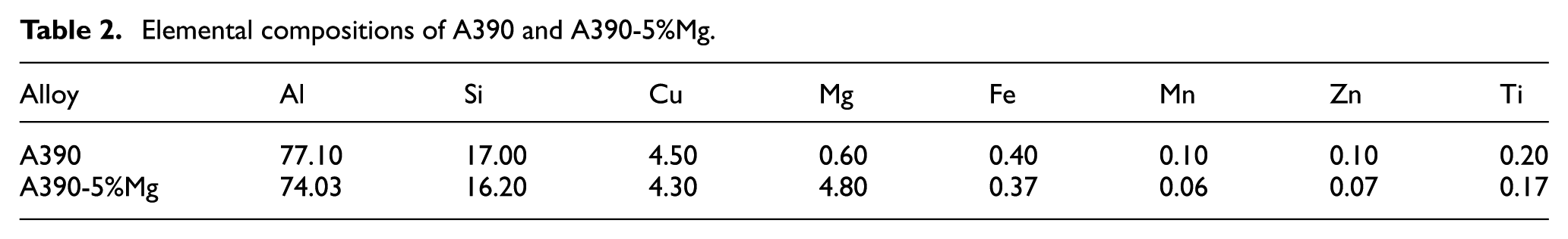
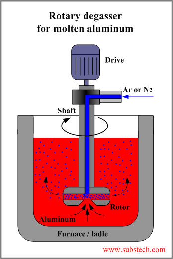
The chemical composition of A390 aluminium alloy is given in Table 2. A calculated kilogram of the commercial A390 was charged into the induction furnace. The alloy was processed in clay graphite crucibles. Degassing of the molten metal to prevent hydrogen entrapment was done at 720°C by rotary impeller degassing (RID) machine, as shown in Figure 4. The RID set parameters were as follows: rotor speed − 500 r/min, gas (Nitrogen) flow rate – 0.4 m3/h and refining time – 15 min, in accordance with previous studies. 13 The rotary graphite shaft was placed about 50 mm from the centreline in order to avoid vortex formation. The molten metal was poured into a circular mould, rotating at a constant speed of 1200 r/min, and held at this speed for 5 min before it was stopped.
Elemental compositions of A390 and A390-5%Mg.
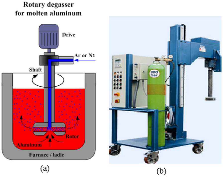
(a) Schematic of degassing facility 14 and (b) degassing facility (RID machine).
A390-5%Mg aluminium alloy formation
Commercially available A390 alloy was used as the raw material for the production of A390-5%Mg ingots. For the A390-5%Mg ingot preparation, 5 wt% of pure magnesium (Mg) was added to the molten metal of A390 alloy at 750°C, which is about 100°C above A390 melting point temperature. 15 The ingot was processed in clay graphite crucibles, and degassing of the molten metal to prevent hydrogen entrapment was done by adding hexachloroethane at 750°C. The chemical composition of A390-5%Mg ingot as analysed by spark emission spectrometer is contained in Table 2.
The A390-5%Mg ingot was charged into the furnace with the addition of 1 kg of pure Mg to account for loss due to oxidation. The molten A390-5%Mg was poured at 750°C into the Pelton turbine bucket mould that was preheated to 300°C and spun at a speed of 1200 r/min. The rotation continued for 5 min after pouring, and Figure 5 shows the vertical centrifugal casting machine used.
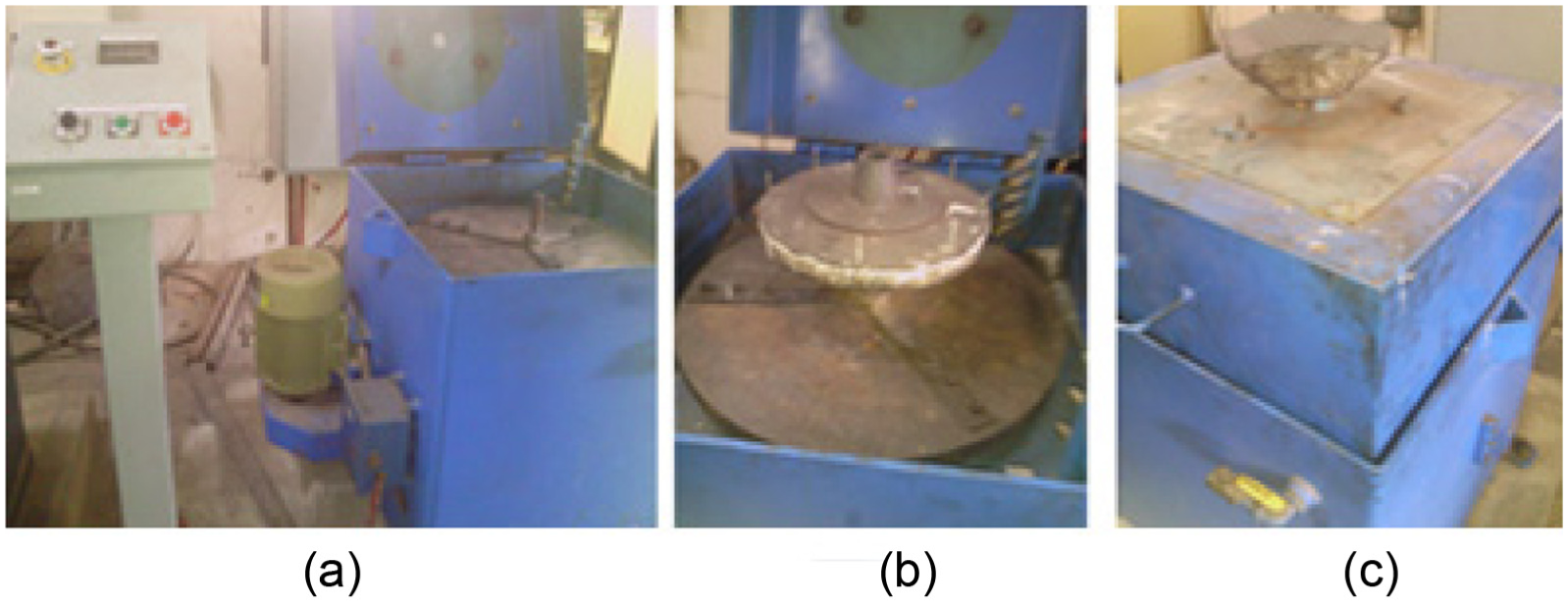
(a) Unloaded centrifugal machine, (b) centrifugal machine with circular mould and (c) centrifugal machine ready for pouring.
The schematic diagram in Figure 6 depicts the arrangement of the buckets in the mould and the direction of rotation. The face of one of the buckets is turned away from the centre of rotation, while the other faces the centre of rotation.

The arrangement of the buckets in the mould.
Apart from the bucket mould, circular and rectangular moulds were also prepared. A390-5%Mg molten metal was poured into the circular mould at a rotational speed of 1200r/min, while the rectangular mould was filled with A390-5%Mg alloy gravity casting. The moulds were preheated to 300°C, and the circular mould was rotated for 5 min after pouring. The castings made are shown in Figure 7.

(a) Pelton turbine bucket cast by centrifugal casting method, (b) cylindrical from circular casting mould cast by centrifugal casting method and (c) castings made by gravity casting method.
Electrochemical corrosion test
A CH Instrument 680 Amp Booster laboratory workstation was used to carry out electrochemical corrosion tests. The setup is shown in Figure 8 and consists of three standard electrodes in a Pyrex glass cell, a platinum counter electrode, saturated calomel electrode as a reference electrode, and working electrode (specimen); 3.5% sodium chloride (NaCl) solution was used as the corrodent. Potentiodynamic current-potential curves were obtained from specimens’ polarisation into cathode (−) and anode (+) as regards the open-circuit potential (OCP) and scanned at 0.05 V/s. Electrochemical impedance spectroscopy (EIS) measurements at the calculated OCP in 1200 s was carried out at frequency range 0.01 Hz–100 kHz at a small-amplitude alternating current (AC) signal (10 mV). Rectangular specimens of dimension 25 mm 25 mm × 2 mm were prepared based on the standard metallographic process: polished with grit emery papers of the following grades 80, 100, 320, 400, 600 and 1000 consecutively and washed with distilled water. 16 This was followed by whirl cloth polishing with 6, 3 and 1 μm SiC particle paste consecutively, washed in acetone and rinsed with distilled water.
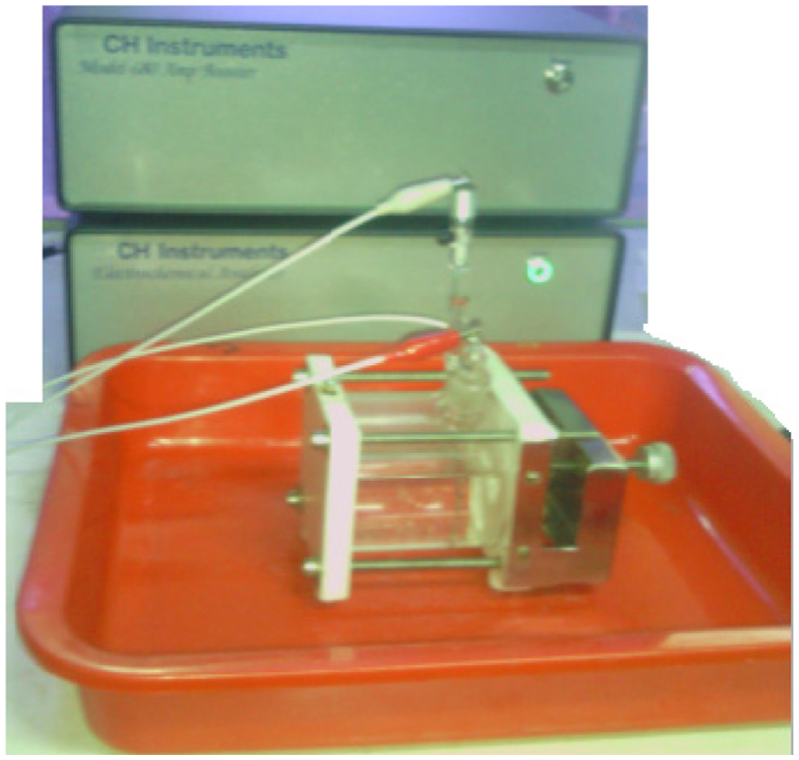
The setup of the electrochemical corrosion laboratory workstation (CH Instrument 680 Amp Booster).
Specimen preparation
The test samples were prepared from A390-5%Mg aluminium alloy formation. The fabricated Pelton bucket was sliced into two equal halves as specimens A and B (Figure 9). This was followed by surface preparation for microstructural examination and hardness test, respectively.

Method of preparing the samples for microstructural examination and hardness test: (a) complete bucket, (b) half of the bucket, (c) surface of plane x-x, and (d) the offset of plane x-x.
Three specimens (C, D and E) were cut from the cylindrical cast, as shown in Figure 10. Specimens C and D were prepared for microstructure examination and hardness testing, respectively.

Schematic of how the specimens were cut from the cylindrical casting.
The electrochemical corrosion test specimens, E1, E2 and E3, were produced from specimen E, as depicted in Figure 11. Specimens F and G were cut from A390 cylindrical cast alloy in the same way as represented in Figure 10. The specimens were prepared for microstructural examination and hardness test, respectively. Furthermore, specimens H and I, fabricated from A390-5%Mg by gravity casting, were prepared for microstructural examination and hardness test, respectively.

Specimens for electrochemical test.
The specimens for the microstructural view were prepared by polishing the surface of the specimens with grit emery papers of 80, 100, 320, 400, 600 and 1000 grades consecutively and washing with distilled water. This was followed by whirl cloth polishing with 6, 3 and 1 μm SiC particle paste consecutively, washed with acetone and rinsed with distilled water.
Hardness test
A Tinus Olsen hardness test machine with 2.5 mm diameter indenter ball was used to measure the macro-hardness of the different specimens in terms of the Brinell Hardness Number (BHN) scale under a load of 62.5 kgf for 20 s. The samples for hardness testing were polished with grit emery papers of 80, 100, 320, 400, 600 and 1000 grades consecutively and washed with distilled water. The offset of the bucket specimen surface prepared for the hardness test and the points where the readings were taken are depicted in Figure 12.

Bucket test samples.
Heat treatment
The same heat treatment process (T6) was carried out on specimens B, D, G and I as represented in the diagram in Figure 13. Temperature of 495°C was used for solutionizing and held for 8 h, followed by quenching with 60°C hot water. Artificial ageing was done at 175°C and held for 8 h.

Schematic of T6-heat treatment profile of A390 and A390-5%Mg.
Theoretical background
In the vertical centrifugal casting process, a particle moving in a molten metal is under the influence of four forces: gravity, FG; drag force (viscosity effect), FD; centrifugal force (due to spinning of the mould), FC and Van der Waals repulsive force (solid–liquid interface movement), FL.
The particle movement is controlled by the net resultant force Fnet17,18

The force balance expression when fluid flow is laminar (Re ≤ 1; assumption) is

where R is the particle radius; g is the gravitational acceleration; µ is the melt viscosity; Δρ = ρp − ρm is the density difference; ρp and ρm are particle and molten metal densities, respectively; ω is the angular velocity and r is the particle position
The direction of the movement of particles is due to centrifugal force, determined by the relative values of the densities; particles are segregated to the outer periphery of the cast if ρp > ρm and vice versa.
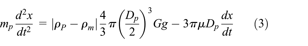
The ratio of the centrifugal force to gravity G is defined as

where dx/dt is the velocity, d2x/dt2 is the acceleration, m is the mass, g is the gravitational acceleration, Dp is the particle diameter, r is the circular mould diameter (m), N is the velocity of mould rotation and µ is the viscosity (m2/s).
The centripetal acceleration, ap, of the reinforcement particle is derived from equations (3) and (4) as


Results and discussion
Microstructure
The microstructural examination of the centrifugal casting of A390 was divided into three zones: the inner zone (Figure 14(a) and (b)), middle zone (Figure 14(c) and (d)) and outer zone (Figure 14(e) and (f)). It was observed that the highest volume of the distribution of fine Si particles of an average size of 5–15 µm was observed at the outer periphery and few at the mid zone. However, the formation of large flakes of α-Al dendrites and bigger Si particles of the average of 25–35 µm were seen in the inner zone.
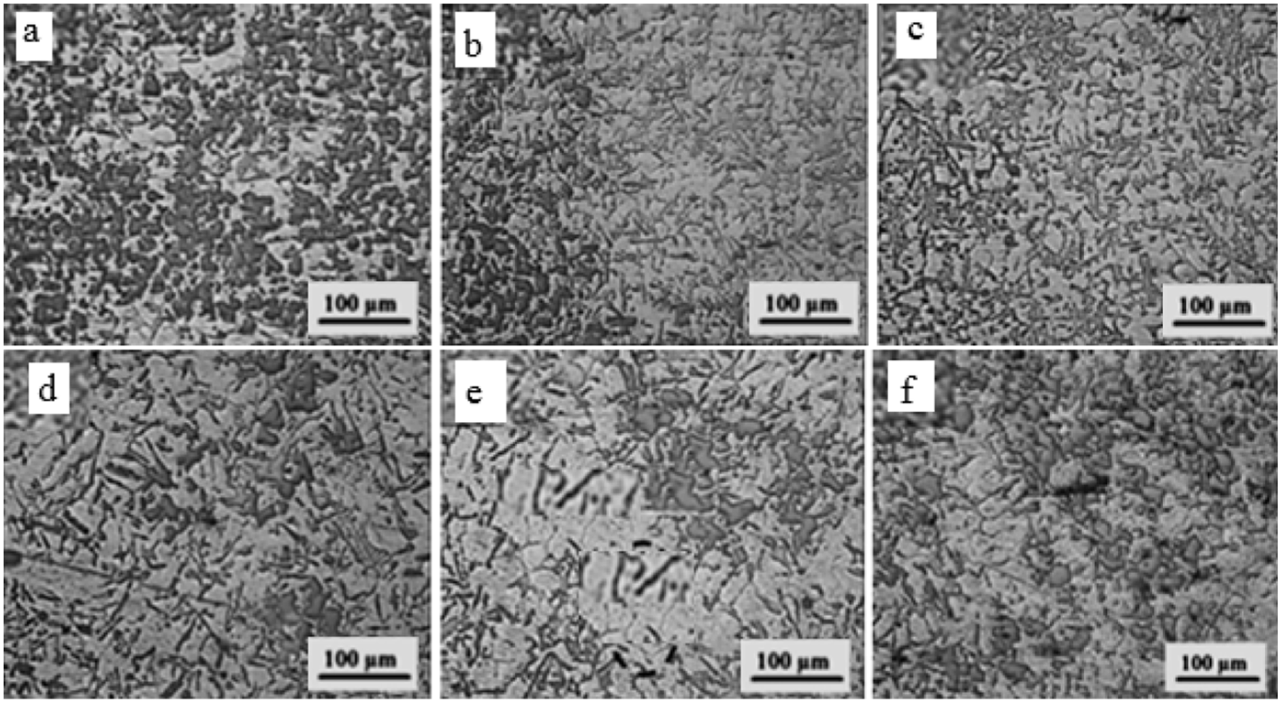
Micrographs of centrifugally cast aluminium A390 alloy, showing the trend of gradient from outer region to inner region (a–f).
The micrographs in Figure 14(a-f), show the gradient of As-Cast A390 alloy fabricated by centrifugal casting method, where a and f are the outer and inner regions respectively. The micrographs of A390-5%Mg alloys fabricated by gravity and centrifugal casting methods are shown in Figure 15(a)–(h). The micrographs in Figure 15(b)–(h) represent the gradient of the microstructure. As can be seen in the micrographs, there is a difference in the microstructure morphology between the gravity cast and the centrifugal cast alloys. In Figure 15(a), large flakes of silicon, coarse Mg2Si, large dendritic cells and large α-aluminium dendrites are seen. In the centrifugal casting alloy micrographs, a fibrous form of silicon is seen in the outer periphery (Figure 15(h)), followed by fine Si particles towards the inner surface. In the inner surface, there are a lot of coarse Mg2Si surrounding Si, and also, polygon primary silicon and large α-aluminium dendrites segregation are standing individually.

Optical micrographs of (a) A390-5%Mg by gravity and (b–g) gradient of A390-5%Mg by centrifugal casting, taken at 15 mm intervals with (g) and (b) at 65 and 145 mm from the centre rotation.
A similar gradient trend to Figure 15, was seen in the bucket specimens as represented in Figure 16. However, the gradients of the two specimens are in opposite directions. It was observed that bucket 1 has a fibrous silicon at the inner surface periphery and coarse Mg2Si and large α-aluminium dendrites at the outer surface. But for bucket 2, the reverse was the case (refer Figures 6, 7 and 9).
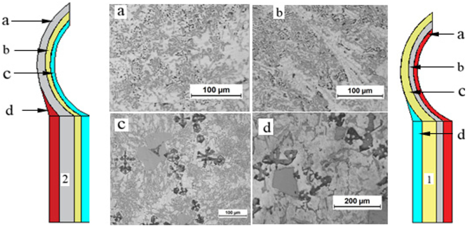
Optical micrograph showing the gradient pattern of A390-5%Mg bucket fabricated by the centrifugal cast process.
The microstructure formation was affected in both the cylindrical cast and the bucket by the centrifugal force generated by the spinning of the mould. Some of the coarse Mg2Si and large primary Si in the microstructure formed were modified and refined by the centrifugal casting technique into fibrous and finer Si. Consequently, this modification and refinement improved the mechanical properties of the alloy.6,18–20 The inherent attributes of corrosion and wear resistance, light weight, the thermal and electrical conductivity of aluminium and its alloys and composites are resultant effects of microstructure modifications.
Fine Si particles are formed from the liquid by the melt rotation of Al-Si-based alloys during solidification. The cooling rate of Al-Si alloys has a strong effect on the microstructure; as such, rapid cooling causes transformation of plate morphology of eutectic silicon to fibre.21,22 Rapid solidification processing (RSP) during liquid to solid-state transition results in grain size reduction, increased alloying elements solid solubility and segregation reduction. Furthermore, amorphous phases and metastable crystalline are formed at times. Rapid solidification is very effective in the production of nanocrystalline of Al-based alloys with Si, rare earth metal (RE), and late transition metal (Ni). 23 Centrifugal casting causes rapid cooling that facilitates the rate of solidification and consequently enhances the quality of casting.
The speed of rotation is a factor that affects the rate at which the microstructure of an alloy is modified and refined. Some studies have put the optimum speed of rotation in centrifugal casting operation between 1200 and 1500 r/min.22,24 The microstructure of both the cylindrical and bucket cast was observed to show the following at the speed of 1200 r/min: changing of large primary Si into needle-shaped eutectic Si near the surface, long needle-shaped eutectic Si transformed into fine primary Si and the formation of fine grain.
The particle acceleration variation and solidification model as related by equation (6) is represented in the graph in Figure 17. The graph shows that the particles of the Mg2Si and Al-Si possess different acceleration at the same speed. This is due to the difference in their densities. The densities of the particles are Mg2Si = 1.93 × 10³ kg/m2; Si = 2.33103 kg/m2 and Al-Si (matrix) = 2.37103 kg/m2.

The particles’ acceleration and centrifugal–gravity ratio curve.
Effect of centrifuge and heat treatment on hardness
The magnitude of the hardness varied between the inner region and the outer region of both the cylindrical cast and the bucket. Maximum hardness of 150 BHN was obtained at points 2 and 6 in Figure 12, while the minimum, 110 BHN, was recorded at points 1 and 5 in the bucket specimen of A360-5Mg-T6. For specimen D, as shown in Figure 18, A360-5Mg as-cast, the maximum hardness (118 BHN) and minimum hardness (87 BHN) were obtained at 140 and 100 mm from the axis of rotation, respectively; maximum hardness and minimum hardness of the heat-treated sample (A360-5Mg-T6) were 157 and 120 BHN, recorded at 140 and 100 mm marks, respectively.

Hardness of A390-5%Mg as-cast by centrifugal casting in relation to the microstructure.
The microstructure formation at the maximum hardness point in as-cast A390-5%Mg is fine and fibrous silicon particles, while voids and α-Al dendrites are the predominant features of the minimum hardness point. Considering Figure 18, the hardness at 140 mm mark is the resultant effect of coarse Mg2Si and large primary Si refinement by the centrifugal force. The high volume of aluminium-insoluble hard Si precipitates at the inner zone is responsible for the 118 BHN hardness recorded.
A non-uniform morphology was seen in A360-T6, as shown in Figure 19(b), due to the formation of smaller Mg2Si and primary Si particles, a fusion of Si and Mg2Si particles and finer and needle-shaped eutectic Si after the heat treatment. A hardness of 147 BHN was observed in 150 mm mark in A360-T6.
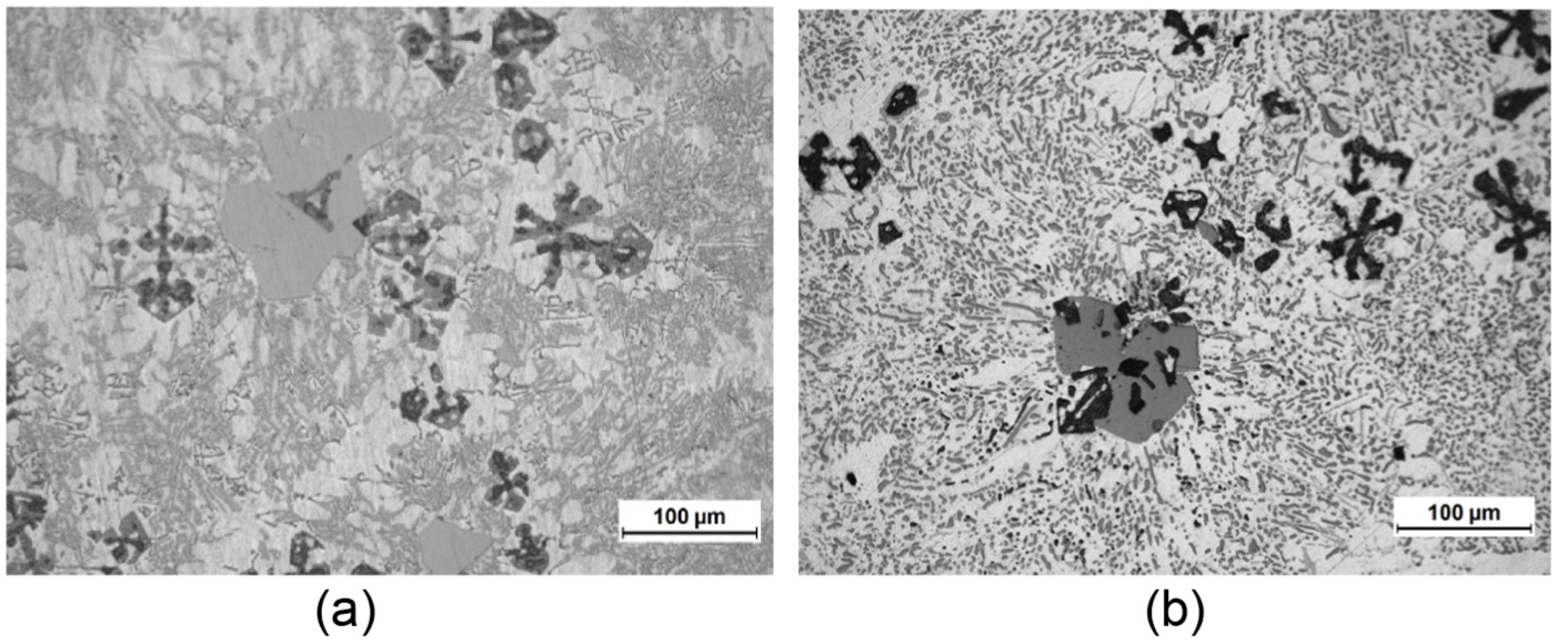
(a) Optical micrograph of A390 as-cast by gravity casting and (b) optical micrograph of A390-6T cast by gravity casting.
A390 belongs to the heat treatable class of aluminium alloy (A3XX series), and studies have shown that thermal treatment process enhances mechanical properties, such as hardness and strength.25–27 The hardness increase that accompanied the T6 is caused by the production of supersaturated solid solution during solutionizing and the re-precipitation during ageing. The T6-heat treatment executes homogeneity of the structure of as-cast intermetallic phases, such as Al2Cu and Mg2Si dissolution and refinement of eutectic silicon morphology.28,29 The modification and refinement, which occurred includes the disintegration of the eutectic silicon branches and spheroidisation of the separated branches.30–33 The high hardness value observed at the inner region of A360-5%Mg-T6, as seen in Figure 20, is due to the high volume of Mg2Si precipitates that dissolved during solutionizing and due to the presence of a cluster of the refined eutectic Si in the region.
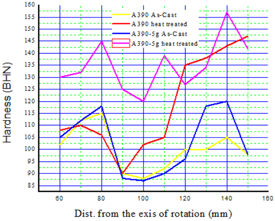
The hardness variation of the A390 and A390-5%Mg by centrifugal casting technique of both as-cast and heat-treated alloys.
Electrochemical corrosion
The difference in corrosion behaviour of A390 and A390-5%Mg alloys in 3.5% NaCl solution is shown in Figure 21 and Table 3. The Tafel (polarisation) curves in Figure 20(a) indicate that lesser corrosion occurred in the A390-5%Mg alloy. The base alloy showed continuous pitting prospect, while the alloy with 5%Mg showed higher resistance. Table 3 presents the A390 and A390-5%Mg alloys in 3.5% NaCl solution polarisation parameters. It was observed that the corrosion current (Icurr) of A390 alloy is higher than that of A390-5%Mg alloy. This means that A390 alloy will corrode more.

Tafel of (a) A390 and A390-5%Mg and (b) specimens E1, E2 and E3 (see also Figure 10).
A390 and A390-5%Mg alloys in 3.5% NaCl solution polarisation parameters.

However, in Figure 21(b), the outer (E1) and the mid (E2) regions show the highest and least resistance, respectively. The A390-5%Mg alloy resistance arrangement as shown in Figure 21(b) is due to the large Mg2Si precipitates at the surface of the A390-5%Mg alloy. This result is in accord with some of the previous studies. Several studies have shown that alloying aluminium with 3%–4% magnesium enhances the corrosion resistance of aluminium and its alloys in seawater. The high corrosion resistance of the Al-Mg system coupled with its mechanical and weldability properties make the alloys of Al-Mg to be widely used in sea shipbuilding and in other seawater-related applications.34–36
Protective coating of Pelton bucket
For functional performance, the surface of the bucket should be hardened and smoothened to withstand the silt erosion, cavitation and pressure from jet water. The use of centrifugal casting and heat treatment processes has tremendously enhanced the Pelton turbine bucket surface hardness and strength properties. However, better surface performance can be achieved by hard surface coating of the bucket. Coating the surface of a bucket with a ceramic material, the use of Al2O3 implanted with Fe micrograins and microarc oxidation (MAO) or plasma electrolytic oxidation (PEO) as coatings will surely enhance the bucket surface performance.
Conclusion
This study achieved the fabrication of a complex-shaped Pelton turbine bucket with improved surface properties using centrifugal casting process. This study observed the following
The mechanical properties of the bucket were improved by 5%Mg addition to A390 alloy, using gravity casting and heat treatment.
A hardness of 143 BHN in A360-T6, fabricated by gravity casting.
The formation of large silicon flakes, large α-aluminium dendrites’ inter-dendrite arm spacing and large dendritic cells by gravity casting.
The formation of small silicon flakes, small inter-dendrite arm spacing and fibrous silicon by centrifugal casting technique.
The mechanical properties of the inner surface (the face that receives jet water) were improved by centrifugal casting technique and heat treatment processes.
The corrosion resistance of A390 alloy in 3.5 NaCl solution was enhanced by the addition of 5%Mg to form A390-5%Mg alloy.
Footnotes
Acknowledgements
The authors hereby acknowledge the Centre for Engineering Postgraduate Studies, management and staff of the University of KwaZulu-Natal.
Handling Editor: Duc Nguyen
Declaration of conflicting interests
The author(s) declared no potential conflicts of interest with respect to the research, authorship, and/or publication of this article.
Funding
The author(s) received no financial support for the research, authorship, and/or publication of this article.