
Abstract
Aiming to improve the low-speed stability and dynamic response while retaining high efficiency, a valve–pump parallel variable mode control for hydraulic speed regulation systems is proposed which establishes a flexible control mechanism using pump control and valve control. At the start and stop stages, the leaking valve control mode is applied to improve low-speed performance by increasing leakages controlled by a valve. At the constant-speed stage, the replenishing valve control mode is used to improve response to load disturbance. At other stages, the pump control mode is applied to make full use of its high efficiency. The three control modes could switch smoothly and the proposed control method could achieve good speed tracking while working efficiently.
Keywords
Introduction
A traditional hydraulic speed regulation system includes two basic types: pump control (PC) and valve control. The valve control system responds quickly to valve and load inputs, but it is less efficient because of inevitable throttling loss. So the valve control system is applicable for applications requiring rapid response with low power.1–3 The PC system is more efficient as it avoids the throttling loss, but responds slowly, so it is suitable to some applications requiring high power with a slow response.1,2,4–6
The valve–pump combination control, which gives full play to advantages of valve control and PC, will make a hydraulic system efficient and offer a rapid response. 7 The combination of control modes has two types: series and parallel. In the valve–pump series control system, a control valve and a pump are connected in series to control the flow together. Manasek 8 proposed a valve–pump series variable speed hydraulic system to accelerate the response of the PC, in which a flow control valve is installed, in series, in the main circuit. An energy-regulating device is added to the above system and forms a variable speed hydraulic system based on energy regulation.9–11 The energy regulation device can absorb redundant energy during system deceleration, as well as release energy during system acceleration, so the dynamic response of this system can be increased. The flow control valve limits the maximum flow in the system, and therefore the above serial control systems are unfit for large flow systems operating at high power.
In the valve–pump parallel control system, the flow control valve is mounted, in parallel, in the main circuit, so the parallel control system is suitable to applications with large flow and high power. Recently, research into parallel control systems mainly focuses on electrohydraulic actuators (EHAs),12–14 which are positioning servos. These parallel control devices can only improve system response characteristics but exacerbate the problem of low-speed performance. Moreover, these parallel control systems have a drawback in principle: there are no replenishing arrangements in such compound systems which are closed cycle systems, and the authors try to control the actuator and replenish fluid in the system using only the valve control branch circuit. During the control process, the valve flow depends on control requirements and is usually variable, but the replenishing flow depends on load pressure and is usually comparatively constant, so the control valve cannot give consideration to both functions.
There is another kind of valve–pump parallel control system called a paralleled valve control servo system, of which there are two types: a throttling system15,16 and a compensating system. 17 The control valve is in its leaking status in the former and, on the contrary, in its replenishing status in the latter. Therefore, the latter has a higher stiffness. The parallel valve control system is a type of constant servo, in which the pump operates in fixed displacement status and supplies the majority of the required flow, and the bypass valve is used to realize a rapid response to load disturbance.
In many engineering applications, some control systems requiring a lot of power (e.g. hydraulic winches) may undergo obvious speed regulation stages including start-up, acceleration, uniform, deceleration and stopping 18 and require comprehensive properties, such as low-speed performance, rapid response to load variation and retention of their high efficiency. Valve–pump parallel control systems cannot meet all these requirements due to their fixed control mode. 19 In this article, a new type of valve–pump parallel control system is presented, that is, the valve–pump parallel variable mode control system; its control modes can vary with control requirements during the regulation process.
This article is organized as follows: system principles are presented in section ‘System principles’, system mathematical modelling is covered in section ‘Mathematical modelling’, dynamic performance analyses (such as low-speed performance, rapid response) are discussed in section ‘Dynamic characteristic analysis’, valve-pump parallel variable mode control of whole regulation process is discussed in section ‘Variable mode control’, the parallel control system efficiency is qualitatively analyzed in section ‘Efficiency analysis’, and conclusions are drawn in section ‘Conclusion’.
System principles
Figure 1 shows the hydraulic principle diagram of the proposed system. It is a closed cycle system and has an individual replenishing arrangement to supplement system leakages and maintain the pressure stability of the low-pressure chamber. The heat exchanger is used to exchange hot fluid from the return chamber and balance system flow. The proportional directional valve (PDV) is connected to high-pressure chamber through a shuttle valve to drive the hydraulic motor with the pump and could work in both replenishing status and leaking status according to control signals received. The load pressure of the loading system is controlled by the proportional relief valve. The speed of the hydraulic motor is measured and fed back to the controller via the encoder, and the controller outputs two control signals: one to the PDV to regulate its opening and another to the pump to change the pump speed. Figure 2 shows the principle in a duty cycle:
Under the leaking valve control (LVC) mode at the start and stop stages. During the two stages, the variable pump works as a fixed pump and discharges a certain amount of fluid flow, which is equal to the system flow producing a stable speed in the hydraulic motor. The PDV, with a pre-opening, is given negative currents to form a bypass leakage passage and improve the low-speed performance of hydraulic motor. At the start-up stage, the valve opening gradually closed, and the motor speed gradually increased, and vice versa at shut-down.
Under variable PC (VPC) mode at the accelerating and decelerating stages. The PDV is closed with zero voltage, and the motor speed varies with pump displacement.
Under the replenishing valve control (RVC) mode at the uniform stage. The pump maintains a fixed displacement and supplies a certain fluid flow, which is less than the flow required at the desired motor speed, and the valve is given a positive current to provide compensatory fluid flow to the forward chamber and improve the dynamic response to load disturbance.

Hydraulic principle diagram of the proposed system.

Speed regulation process in a duty cycle.
Therefore, the ‘variable mode control’ means that system control modes could vary with regulation requirements, which can make full use of advantages of PC and valve control to allow low-speed stability and fast response while retaining its high efficiency.
Mathematical modelling
Although such a hydraulic system is typically non-linear, the proposed system is described in linear form because of the following: (1) currently, the theory and analysis of non-linear system are undeveloped and immature, so some non-linear equations, especially those which describe the pressure–flow curves of hydraulic control valves, should be linearized under special conditions. (2) Even if non-linear solutions are easily obtained, all of them would not be ill-suited because design procedures and performance specifications are based on linear theory. (3) The proposed system, made up of PC, valve control and valve–pump compound control, is new and complicated and is difficult to express using non-linear equations; however, we can learn much from the linearized theory of PC and valve control which are comparatively mature and justified and find relevant knowledge in Merritt 1 and Manring. 2 Therefore, linearized analysis is essential to, and suitable for, this work.
To linearize the system, the linearization point should be clear and definite because coefficients of the linearized equations, such as the valve coefficients, flow gain and flow–pressure gain, vary with operating point. The most important operating point is at neutral (where
Variable pump link
Figure 3 shows the variable mechanism of a variable pump. The mechanism consists of a piston, a position sensor, a servo valve and a proportional–integral–derivative (PID) controller, used as a positioning servo system.18,20,21
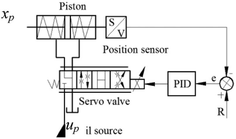
Schematic of the variable mechanism.
As suggested elsewhere, 18 the positioning servo system could be simplified as a first-order inertia link, that is
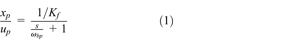
where

where

where
Valve control link
The parallel control valve PDV is a critical centre spool valve and is matched symmetrically. Its orifice equation is given by

where Cd is the discharge coefficient, w is the area gradient, xv is the valve displacement,

where Kd is the gain in the valve dynamics. Hence, the orifice equation of the valve can be expressed as

where Csv is the valve constant and
Using a Taylor series, the linearized orifice equations are written as

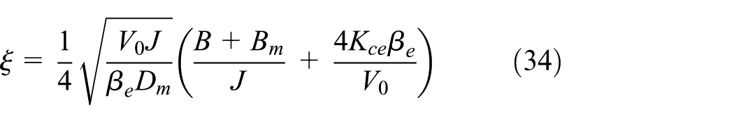
where Kq is the flow gain of the PDV, and Kc is the flow–pressure gain of the PDV.
Under LVC mode, the PDV works in its leaking status, and the pressure drop

So the linearized flow equation of the valve in its leaking status is

where Qvl, Kql, Kcl and Ivl are the flow, flow gain, flow–pressure gain and control input of PDV when leaking, respectively.
Under RVC mode, the valve works in its replenishing status, and the pressure drop

where Ps is the supply pressure of the PDV, and its linearized flow equation is

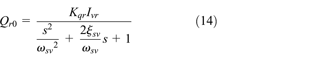
KcPs is constant and should be omitted because the linearized flow equation is an incremental equation. Hence, the linearized flow equation of the valve in its replenishing status is

where Qvr, Kqr, Kcr and Ivr are the flow, flow gain, flow–pressure gain and control input of the PDV at replenishing status, respectively.
Considering the PDV as a second-order oscillating link, its unload flow at leaking status Ql0 is given by

where
Hydraulic motor link
Under LVC mode, the total system continuity equation is

Under RVC mode, the total system continuity equation is

where Cm,
The torque balance equation for the hydraulic motor is

where J is the equivalent total inertia and
Combining equations (3), (9), (13), (15) and (17), the open-loop dynamic equation of the parallel control system under LVC mode is given by
where
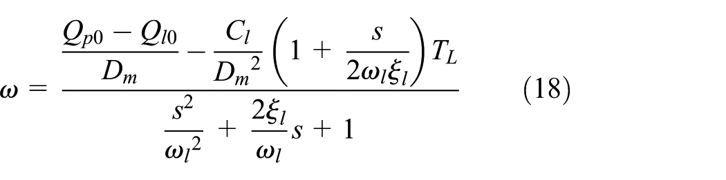
Combining equations (3), (12), (14), (16) and (17), the open-loop dynamic equation of the parallel control system under RVC mode is
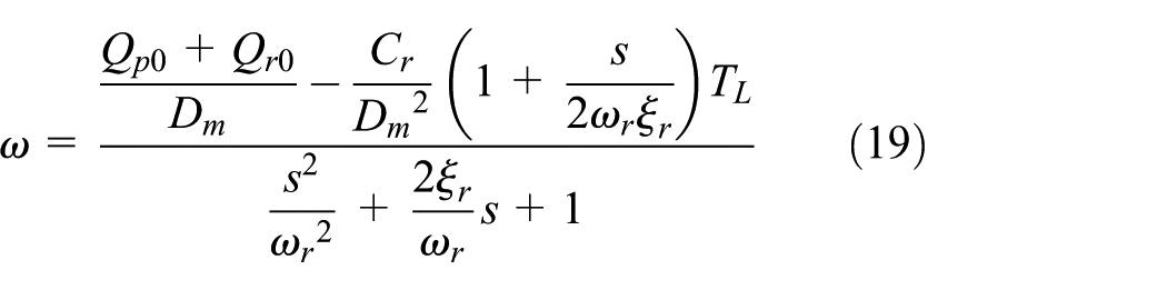
where
When the PDV is closed, the LVC mode and RVC mode will switch to VPC mode,2,6 and its open-loop dynamic equation is

where
The rotary part is simplified as a proportional element due to its fast response, and

where um is the feedback voltage, Km is the feedback gain and nm = 60wm/(2π) is the motor’s rotational speed.
Total system mathematical model
Figure 4 shows the control block diagram of the parallel control system, which is made up of a valve control link, a variable pump link and a hydraulic motor link. The system parameters are listed in Table 1. The parameters Dm, V0 and J are set according to the actual product. The total leakage coefficient, natural frequency and damping ratio under the three different control modes are calculated by formulas in equations (18)–(20). The compensated open-loop gains under three different control modes, K1, K2 and K3, are determined by formulas in equations (28)–(30) and stability criterions:

Block diagram of the proposed system.
System parameters.

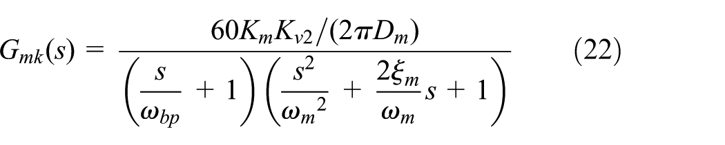
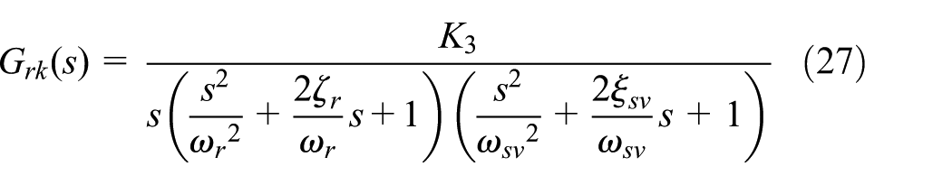
The uncompensated open-loop transfer functions of the proposed system under VPC mode, LVC mode and RVC mode are, respectively, given by


These velocity servo loops are of Type 0 and offer poor performance (with regard to stability) due to their low phase margin, especially for the usual case of a low damping ratio


where
The static closed-loop speed stiffness under VPC mode, LVC mode and RVC mode are, respectively, given by


Dynamic characteristic analysis
Simulation model
Figure 5 shows the simulation model of valve–pump parallel control as run on AMESim, a professional multidisciplinary simulation software suite, is widely applied in hydraulic, automation and so on. 22 In general, an AMESim simulation needs four steps: sketch > sub-models > parameters > simulation.

Simulation model as run on AMESim.
The key components of AMESim are listed in Table 2. FP04 is used to set the characteristics of the hydraulic fluid, in which the effective bulk modulus is 1400 MPa. To simulate the total leakages of pump and motor Ct, a fixed orifice is installed into two chambers of the hydraulic motor and is set to 1 L/(min MPa). The rated voltage of variable pump is set to 10 V corresponding to its maximum displacement. The rated input of the PDV is 40 and −40 mA corresponding to maximum positive and negative opening, respectively. Many types of loads, such as sinusoidal load, ramp load, step load and square load, are applied to the system by feeding different inputs to the proportional relief valve. A controller is built, which could switch between VPC, LVC and RVC modes.
Key components of the AMESim platform.

PDV: proportional directional valve.
Low-speed performance analysis
Theoretical basis
The factors influencing the low-speed stability of hydraulic motors mainly include external factors (flow and pressure ripple of oil source, load disturbance) and integral factors (friction torque, motor displacement ripple, leakages). However, the friction torque is the principal factor.23,24 Friction is a complex non-linear physical phenomenon and can be approximately described by static models or dynamic models.25–27 Figure 6 and equation (30) show a normal static model for friction torque, which takes Coulomb friction, stiction and viscous friction into account. The Stribeck effect is described by the third item of equation (31)

where

A normal static friction model with Stribeck effect.
The Stribeck effect is often used to describe the friction behaviour of low-speed regions, that is, friction torque decreases as speed increases when

where
In the low-speed region, because of the Stribeck effect, the slope between friction torque and speed is negative, that is,
In Figure 6, ns is a critical speed, and the actual motor speed will oscillate below that speed, but the oscillation will disappear above it: this is called the stick–slip phenomenon, and ns is given by28,31,32
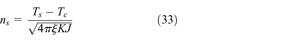
where K is the system stiffness and
Therefore, increasing
Research shows that the negative value of B becomes larger and
In addition, the phenomena of flow and pressure ripple are inherent to a piston-type variable displacement. 35 Moreover, its variable mechanism usually oscillates with a small displacement due to friction and the dead band of PDV, which will aggravate the flow, pressure ripple in the oil source and low-speed instability of the motor.
Based on the above analyses, LVC is applied to low-speed stages, which has the following advantages:
Pump displacement could work within a stable region, which will make the flow of oil more stable and avoid using variable displacement pumps for good low-speed stability.
Increased damping ratios and total leaking coefficients will result in a lower critical speed and improve low-speed stability.
The variation in damping ratios due to valve control is contrary to that of the damping ratios in the low-speed region, which could compensate for the reduction in damping ratios because of the friction’s decreasing trend, thus helping to improve lower critical speeds.
Verification by simulation
To avoid the instability due to closed-loop control, this simulation is carried out in open-loop control. The friction model with Stribeck effect is applied to simulations, and the parameters are as follows: Ts = 600 N m, Tc = 400 N m, Tv = 0 and ns = 10 r/min.
Figure 7 indicates the influences of the Stribeck effect on friction torque and motor speed in PC mode. It shows that the transition from static torque to Coulomb friction torque is exponential, not instantaneous, after adding the Stribeck effect, which causes motor speed instability. The simulation results prove that the friction model, with the Stribeck effect, could simulate the actual friction in motor. Figure 7(b) also indicates that the motor cannot offer a good low-speed performance in single PC mode.
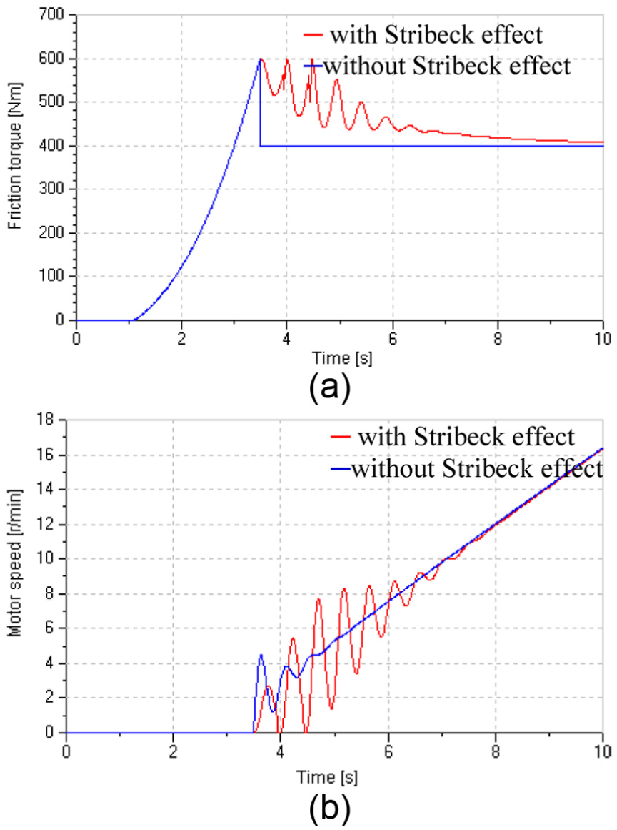
Influences of the Stribeck effect on friction torque and motor speed in pump control mode (J = 70 kg m2): (a) friction torque and (b) motor speed.
Figure 8 shows the influences of different valve pre-openings on start performances under LVC mode. Figure 8(a) indicates control inputs of the PDV and pump. Keeping the pump inputs constant (up = 2 V corresponding to QP = 8 L/min), the valve inputs, respectively, change from −10, −20, −30 mA, to 0 mA, corresponding to valve pre-opening decreases from 25%, 50%, 75%, to 0%, respectively. The red curve (0% pre-opening) is the pump input in only PC. Figure 8(b) and (c) indicates that under LVC mode, total leakage coefficient and damping ratios become large and increase with valve inputs and reach a maximum when the motor starts to move, but under PC mode, the parameters are small and constant and are barely affected by the pump inputs. The reasons for this are as follows: comparing equations (18) and (20), the total leakage coefficient under LVC mode, Cl = Ct + Kcl, increases by introducing the valve flow–pressure coefficient Kcl, for valve control. Ct is usually small and constant, but Kcl is much greater than
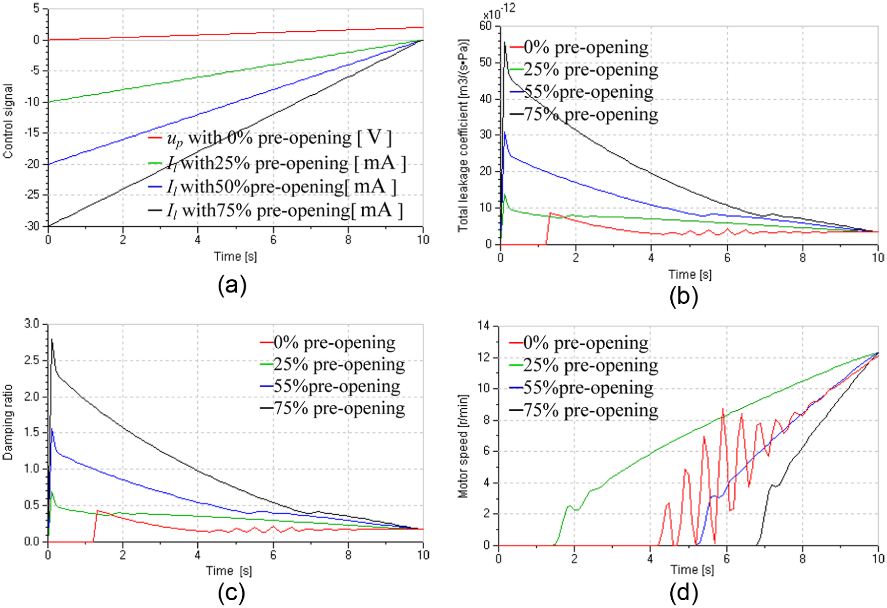
System response under LVC mode: (a) inputs of valve and pump, (b) total leakage coefficient, (c) damping ratios and (d) motor speed.
According to equations (32)–(34), the low-speed performance could be improved by increasing J, which is verified in Figure 9; however, increasing inertia will reduce the system natural frequency and response speed, will require more space and will increase the weight and cost of the system. Therefore, increasing leakage by LVC is more economical and flexible than increasing system inertia.

Influence of inertia on damping ratios and motor speed in pump control: (a) damping ratios and (b) motor speed.
Similar performances will be obtained when applying LVC to the stop stage. Stability in open-loop control is conducive to stability in closed-loop control, so, as shown in Figure 10, compared with the system under PC mode, that under LVC mode could achieve good tracking and low-speed performance in closed-loop control.

Low-speed performance of the motor in closed-loop control.
Rapid response performance analysis
According to section ‘System principles’, RVC is used to obtain a rapid response to load disturbance in the constant-speed stage. In fact, LVC is also variable after the start stage, which means that the valve cannot be closed totally and should be kept open by a certain amount in the constant-speed stage to obtain a rapid response by controlling leakage. In this section, RVC is compared with PC and LVC. In the constant-speed stage, the motor speed is high, so the Stribeck effect is ineffective and can be omitted.
Influences of load variation on system parameters
First, we discuss the influence of load pressure on system parameters, such as total leakage coefficient, damping ratios and speed stiffness. This part is discussed in open-loop control mode terms. Figure 11 shows the effects of load variation on total leakage coefficient. The load is produced by the proportional relief valve and is similar to square waves and varies between 6 and 10 MPa.

Total leakage coefficients under variable loads: (a) Ct under different modes, (b) under LVC mode and (c) under RVC mode.
Figure 11(a) shows that compared with Ct under VPC mode, those under RVC and LVC mode are similar to square waves. Compared with Cl in Figure 11(b), Cr in Figure 11(c) is more stable, so the system under RVC mode has comparatively stable total leakage coefficients. We can find the reason from the expressions for Ct, Kcl and Kcr, that is,
The influence of total leakage coefficient variation caused by variable loads under different modes has two facets:
For damping ratio, the damping ratio is proportional to total leakage coefficient, and Figure 12(a) shows that for the same valve opening, damping ratios in LVC and RVC are greater than that in VPC, but damping ratios in RVC are more stable than that in LVC and VPC modes. Therefore, the system in RVC mode has more stable parameters, which helps parameter prediction and system control.
For speed stiffness, speed stiffness vary inversely with total leakage coefficient, and Figure 12(b) shows that motor speeds in LVC and RVC are more similar to square waves compared with that in VPC, which implies that the system in valve–pump parallel control has lower speed stiffness and is more sensitive to load variation because of the increased leakage.

Damping ratio and motor speed response under variable loads: (a) damping ratios and (b) motor speed.
Although regular trends are obtained (see above) in open-loop control, they are still variable under closed-loop control.
Rapid response performance analysis
This part is discussed in closed-loop control mode terms. As discussed in section ‘Total system mathematical model’, the three control loops are corrected by integral links, and the gains are set to KmI = 1.5, KlI = 25 and KrI = 25, respectively. The pre-opening current is 15 mA under LVC mode:
For the same step load, the speed drop in RVC is smaller than that in LVC and larger than that in VPC, which shows that speed stiffness in RVC is greater than that in LVC and lower than that in VPC. That is because the speed stiffness is inversely proportional to the total leakage coefficients according to equations (28)–(30), and Ct < Cr < Cl as shown in Figure 13(b).
System parameters in RVC are more stable than those in LVC. Figure 13(b) and (c) shows that total leakage coefficients and damping ratios in LVC change widely, for example, the damping ratio changes from 1.6 to 0.5, but these parameters are comparatively constant in RVC, for example, the damping ratio is about 0.5.
Compared with PC, valve–pump parallel control responses to load variation are rapid because, first, systems under the chosen three control modes have the same natural frequency, that is,
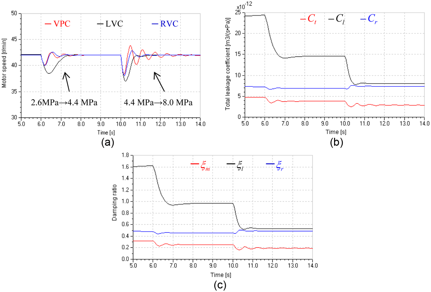
Response for step loads: (a) motor speed, (b) total leakage coefficient and (c) damping ratio.
Figure 13 shows the step response in the three control modes, and we find that the system in RVC mode response is less susceptible to load variation compared with that in LVC. As shown in Figure 13(a), the system in LVC responds rapidly at high load pressure (e.g. at t = 10 s) and slowly at low load pressure (e.g. at t = 6 s), which is even slower than that in VPC. The reason is as follows: according to
The system under RVC mode could provide two benefits by raising the supply pressure Ps of the control valve as shown in Figure 14:
Accelerating response. According to flow gain
Improving speed stiffness. According to flow–pressure coefficient

Motor speed response for step load under different values of Ps.
However, the system in LVC mode does not have such flexibility, because, when the control valve works in its leaking status, its flow gain
Variable mode control
Now valve–pump parallel variable mode control is applied to the whole regulation process based on the above analyses. As shown in Figure 6, the system is loaded by a loading pump and a friction model described by equation (31), with Ps set to 15 MPa, and step disturbances at 20 and 28 s. The variable mode controller is developed and could change control modes according to the reference speed n (n = um/Km, nmax = 54 r/min). When
The switch points are set by the following rules: the switch point at low speed should be set to the minimum stable speed obtained in single PC, and the pump’s initial displacement is determined by the sum of this flow corresponding to this speed and any leakage from pump and motor. Meanwhile, the valve pre-opening should be set to leak the flow corresponding to this speed in its entirety. Therefore, according to the simulation results in section ‘Low-speed performance analysis’, this speed is set to 12 r/min, the initial voltage of the pump is 2 V, the flow corresponding to that speed is 8 L/min and the initial current through the PDV is −13 mA corresponding to 32.5% valve opening. The switch point for high-speed operation is slightly less than nmax and is set to 52 r/min.
Figure 15 shows the dynamic response of the system in valve–pump parallel variable mode control and in single PC in a duty cycle. Figure 15(a) indicates that compared with PC, the valve–pump parallel control achieves good low-speed stability by LVC at start and stop stages and rapid response to load variation by RVC throughout the constant-speed stage. Moreover, the valve–pump parallel control system achieves good speed-tracing accuracy in the overall regulating process and switches smoothly between the three modes.

System responses in a duty cycle: (a) motor speed, (b) speed error, (c) damping ratios and (d) system pressure.
Figure 15(b) shows that the speed error in variable mode control is smaller than that in PC in the above three stages. Figure 15(c) shows that the damping ratios in variable mode control are more stable and are also greater: they increase as the speed decreases at the start and stop stages which matches earlier supposition. Figure 15(d) shows the system in variable mode control to undergo a smaller pressure shock especially in the low-speed stage.
As shown in Figure 16, during the closed-loop control process, trends of the changes in the valve and pump meet expectations, and the corresponding flows in the pump and valve are continuous and without mutation.

Valve and pump responses in a duty cycle: (a) control signals of valve and pump and (b) valve flow and pump flow.
Efficiency analysis
After addressing concerns about system dynamic response in variable mode control, we now analyse the system efficiency. The power of hydraulic systems is the product of pressure and flow, and pressure varies with loads, so the control of energy is essentially the control of flow, which could be controlled artificially. In the valve–pump parallel control system, the system flow, ignoring system leakages, is given by

where Qs is the system flow and also the input flow to the hydraulic motor, Qs = Qp + Qv under RVC mode and Qs = Qp − Qv under LVC mode.
There are two basic control modes in this parallel control system: PC and valve control. PC is more efficient because both flow and pressure are closely matched with the load requirement and this is accompanied by near-zero throttling loss. However, valve control is less efficient because of the unavoidable throttling loss. Therefore, the system energy loss is mainly generated in valve control mode, so the system efficiency

where
Combining equations (35) and (36), the expression for system efficiency under LVC and RVC modes is

In equation (37), ‘+’ denotes RVC mode, and ‘−’ denotes LVC mode. In fact, in this pump–valve parallel control system, the pump provides the majority of the flow and the valve only supplies a little. So

Therefore, we obtain a unified efficiency expression for a valve–pump parallel variable mode control system, and we can draw the following conclusion: the ratio Kpv could be used to describe the system efficiency, and the greater the Kpv, the higher the system efficiency.
Figure 16(b) shows that most of the required flow is supplied by the pump and the valve only provides, or leaks, a small amount of flow throughout the process. So the valve–pump parallel control system offers a high efficiency while achieving a sound dynamic performance overall. In addition, if the maximum speed increases, Kpv will be greater and the proposed system will be more efficient. That is because the majority of the flow corresponding to its maximum speed is supplied by the pump not the valve.
As discussed in section ‘Variable mode control’, modes switch according to speed, so the switch points exert a significant influence on system efficiency. In the start and stop stages, the PDV works in its leaking status and system flow leaks from the valve, so energy loss arises mainly from the valve throttling loss. The higher the switching speed, the more flow leaks and the more energy the system loses. In the uniform stage, the valve works in its replenishing status and the energy loss mainly includes overflow losses and throttling loss. If the switch speed at this stage is too low, the throttling loss will increase. On the other hand, to reduce the overflow loss, a pump with high pressure and low flow characteristics should be selected to supply fluid to the valve, because only a small amount of fluid will flow through the valve at this stage anyway. If conditions allow, the various pump with constant pressure control 36 may be used to improve system efficiency further, and the pump can provide constant pressure and matched flow without overflow loss.
This article mainly studies the influence of valve control on the low-speed stability and dynamic response, and efficiency of the valve–pump parallel control system. In the combined control system, valve control plays only a supporting role, because the pump supplies most of the flow and the valve handles very low flows. Therefore, we only made a comparison between the valve–pump parallel control and PC in this study. We can make a preliminary comparison between the valve–pump parallel control and valve control: only the system in valve control could be characterized with good low-speed stability and rapid dynamic response, but with low efficiency due to the throttle lose result from valve control.
Conclusion
This article presents a valve–pump parallel system with variable mode control, and the following conclusions were obtained:
In the valve–pump parallel control system, the introduction of valve control does not change the system natural frequency, but increases the total leakage coefficients and damping ratios, which vary widely with operating point.
LVC is applied to improve low-speed stability by increasing total leakage coefficients and damping ratios. RVC is applied to accelerate the dynamic response to load disturbance. Compared with LVC, RVC has more stable damping ratio and speed stiffness, and its performance could be further improved by increasing the valve supply pressure.
The valve–pump parallel variable mode control establishes a flexible control mechanism, and control modes could vary with control requirements. The proposed method could improve the overall performance of a hydraulic motor speed system and offer good low-speed performance and a rapid response to load variation while maintaining a high system efficiency.
Footnotes
Academic Editor: Muhammad Akhtar
Declaration of conflicting interests
The author(s) declared no potential conflicts of interest with respect to the research, authorship, and/or publication of this article.
Funding
The author(s) disclosed receipt of the following financial support for the research, authorship, and/or publication of this article: This work was supported by a Project Funded by the Priority Academic Program Development of Jiangsu Higher Education Institutions and the Fundamental Research Funds for the Central Universities (no. 2015QNA33).