
Abstract
This study proposed a user-tracking control algorithm for a powered wheeled walker and examined how it improves the tracking performance of a user. Our newly developed powered wheeled walker based on the mechanism of infant walker and powered wheelchair has enhanced walking stability and needs less physical power to be moved. The walker is able to smoothly track user’s various movements (i.e. forward, backward translation, and rotation) using pelvis motion sensors determining walking direction and stereo cameras analyzing lower extremity motion. In particular, weighting factors of controllers using pelvis motion sensor and stereo cameras can be suitably adjustable online. The experimental testing was conducted to examine walker’s tracking performance, and the results from electromyography testing showed that the walker based on user-tracking control algorithm significantly decreased the magnitude of exerted muscle strength in both upper and lower extremity compared to conventional passive wheeled walker. Thus, we were able to successfully verify that the proposed walker can automatically track a user with gait impairment for safe walking without a helper.
Introduction
The need for walking assistive or rehabilitation device has gradually increased for the elderly and people with neurological or musculoskeletal disorders.1–3 The population of age 65 years and above exceeds 11% since 2010 in South Korea. The main issue of the growth of the elderly population is that many of them have difficulty in moving their body segment properly. Especially, when they have gait impairment, their quality of life would be very low.
To rehabilitate the elderly and people who have gait impairment, walking assistive/rehabilitation device is necessary.4,5 There exist two main walking assistive/rehabilitation devices, which are folding walker and wheeled walker (Figure 1). Folding walker has greater stability, but less mobility, while wheeled walker is more mobile, but less stable. Since both of these passive walking assistive devices can only be operated by users’ both arms, movements of arms are limited. In the event that users lose handle during walking, the risk of falling is very high.

Photographs of conventional walking assistive/rehabilitation device: (a) folding walker and (b) wheeled walker.
To compensate the defect of passive walkers, a number of researchers have worked to develop powered wheeled walker with robot technologies.6–8 Some of them have capability to help users walk properly and to guide them through a safe walking path using laser and also ultrasonic sensors. Han et al. 9 developed an intelligent walking-aid robot. This robot provides physical support and mobility aid for the old adults during walking by measuring the handle force between the user and the robot. In addition, a laser range finder is used to detect the distance between the robot and the user’s leg. Akimoto et al. 10 proposed a model-based development method with a user model. They used this method to improve a rehabilitation assistance function that has no risk to hurt subjects. Zhu and colleagues11,12 developed an omnidirectional mobile robot capable of walking support and rehabilitation for the elderly or the disabled. They attached a six-force/torque sensor to a handle bar to check the user’s walking intention and also attached a two-dimensional (2D) laser ranger/area-finder to detect the obstacles. Grondin et al. 13 developed an intelligent rule-based controller for a smart walker with powered wheels and a handle force/torque sensor to achieve smooth interaction between the user and the walker. Chugo et al. 14 proposed a robotic walker system capable of both standing and walking assistances. Rodriguez-Losada et al. 15 developed Guido that is able to walk along safer path based on the information from mapping and is controlled by built-in force sensor in handle. Spenko et al. 16 developed Personal Aid for Mobility and Monitoring (PAMM) which is a robotic device to provide support, guidance, and health monitoring for the elderly. Absolute locations of robots are recorded using cameras detecting markers on the ceiling, and direction to destination is provided. In addition, robots record users’ gait-related information, heartbeat, and electrocardiogram (ECG).
Most of the currently available wheeled assistive walkers rely on force sensor in handle to check walking will. These walkers, however, restrict users’ hand and arm movements. In addition, the method to control walkers using the amount of forces applied by hands might be hard to be familiar for the elderly since there is no direct relationship between hand force and walking condition. In particular, these walkers have no system to completely prevent users from falling.
We have developed a powered wheeled walker, that is, motor-driven wheelchair and baby walker combined in order to prevent users from falling, that allows to use both arms and realize real ground walking without pulling the walker, thanks to motors since 2013.17,18 Figure 2 shows the design concept. In particular, the real-time motion capture technique is utilized for rapid user tracking. In this article, we developed a feedback and feedforward tracking control algorithm using pelvis and lower extremity motions collected by pelvis motion sensors and stereo cameras to reduce reaction time and to increase tracking accuracy. For a suitable tracking control, weighting factors of feedback and feedforward controllers are adjusted during walking. In addition, we examined the developed control algorithm performance by conducting walking experiments with electromyography (EMG) quantitatively.
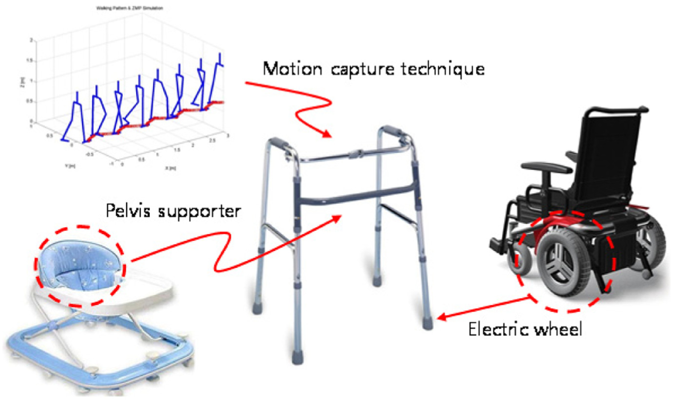
Conceptual design.
Powered wheeled walker
The developed powered wheeled walker is shown in Figure 3. 30 × 30 mm2 aluminum profile that has greater strength per weight was used as frames in the walker. The inner space dimensions of walker (width: 830 mm, depth: 800 mm, and height: 1200 mm) were determined considering average elderly people’s pelvis height and step length. Recognizing that average distance between pelvis and landing foot is 380 mm, the distance between pelvis supporter and front frame was chosen as 440 mm in order to prevent feet from hitting the walker during walking. Cameras were installed on the left and right sides of the walker.

Photographs of the developed powered wheeled walker.
Main control system of the walker using TMS320F2812 is shown in Figure 4. Main controller receives users’ walking information from two rotary potentiometers measuring pelvic rotation and stereo cameras capturing lower extremity movements via an embedded PC. Main controller sends desired motor speed to wheel motor controller using CAN communication. To operate two 200-W motors simultaneously, CUBE2408-DID motor controller (Robocube Tech, South Korea) is used with 10-ms sampling time command from main controller. Video information by stereo cameras is sent to main controller with 15 fps through open library (OpenCV). Stereo camera with infrared filter replaced expensive infrared camera, and adding wide-angle lens provide wider angle of field. Also, the main controller controls the pelvis supporter motor to adjust the height of the pelvis supporter.

Control system diagram.
The height-adjustable pelvis supporter prevents users from falling and reduces loading applied to users’ lower extremity. Pelvis motion sensors located on the left and right sides of the pelvis supporter track users’ walking will and direction by measuring rotational angle using variable resistance (Figure 5). Rotational part of pelvis motion sensors is connected to pelvis supporter and rotates based on users’ motions. Leaf springs on the left and right sides of the rotational part make it return to center when no forces are applied. Height-adjustable stereo cameras located on the lateral side of the walker record lower extremity movements closely with additional wide-angle lens (Figure 6).

Photographs of the pelvis motion sensor.

Photographs of the infrared camera system.
User-tracking control algorithm
Feedback control using motion sensors
User-tracking control algorithm consists of (1) feedback control using pelvis motion sensors, (2) feedback control using stereo cameras, and (3) feedforward control using stereo cameras. Pelvis motion sensors determine moving direction and speed based on location and rotation of pelvis measured by rotational potentiometers (Figure 7). Angular speeds of left and right wheel motors of the walker are determined by the following equation

where ωrm1 and ωrm2 are the angular velocities of the right and left wheel motors, respectively, and θrp and θlp are the right and left angular displacements of pelvis motion sensors, respectively. Proportional gain (k1) was experimentally set to 80 r/min/degree considering a slow walking speed (50 m/min). Right pelvis motion sensor is associated with right wheel motor, while left wheel motor is operated by left pelvis motion sensor. Positive rotational angles in motion sensor drive move forward while negative rotational angles lead to backward movement. By using this simple strategy, the angles of the right and left pelvis motion sensors are controlled to be zero through integral control actions, and the walker can follow the user.

Four types of walking principles according to pelvis motion sensors.
Feedback control using stereo cameras
Infrared cameras installed on the left and right sides of the walker collect users’ lower extremity kinematics. The reason that we added stereo cameras to the walker was that tracking control only using pelvis motion ignores lower extremity kinematics during the swing phase, which results in slower response time. To capture users’ lower extremity kinematics, infrared markers were attached to knee and ankle (Figure 8). Average values over four marker locations (i.e. centroid of two-dimensional positions of all four markers) are used as the human position with respect to the walker’s position. As shown in Figure 9, positive value of center position of markers indicates forward walking, while negative value of it means backward walking. The simple control law used to this strategy is as follows

where ωrm1 and ωrm2 are the angular velocities of the right and left motors, respectively, and Δx is the forward center position of markers with respect to the location of the camera. Velocities of wheel motors are generated based on Δx, so that Δx can be zero through integral control action. The proportional gain (k2) here was set to 10 r/min/pixel based on the video recorded using cameras.

Four infrared marker positions.

Schematic diagram of feedback control using stereo cameras: (a) standstill and (b) walking.
Feedforward control using stereo camera
In the above feedback control algorithm using stereo cameras, there certainly exists minor tracking error during walking. In this section, the goal of the feedforward control used was to improve the response time of walker’s motion tracking based on human walking patterns.
The first step of this feedforward control is to detect users’ walking phases such as swing and stance phases by lower extremity kinematics (knee and ankle), and then the walker goes forward, backward, or stops. Swing phases are defined as when the height of ankle is greater than 200 pixel (≅ 120 mm) determined based on the results from repetitive experiments (Figure 10).

Determination of swing/stance phase using ankle height: (a) standstill and (b) walking.
After determination of swing/stance phase, walking direction is determined based on shank angles at the beginning and ending moments of swing phase (Figure 11). The detailed algorithm is as follows


Schematic diagram of feedforward control using stereo cameras: (a) forward walking and (b) backward walking.
As shown in equation (3), if the difference between the shank angles at the beginning and at the ending of swing phase is negative, it is forward walking. If the difference is positive, it is backward walking. dir indicates the walking direction that determines the rotational direction of wheel motors.
Next, walking speed is calculated by step length, and it is used to calculate motors’ feedforward velocities as follows
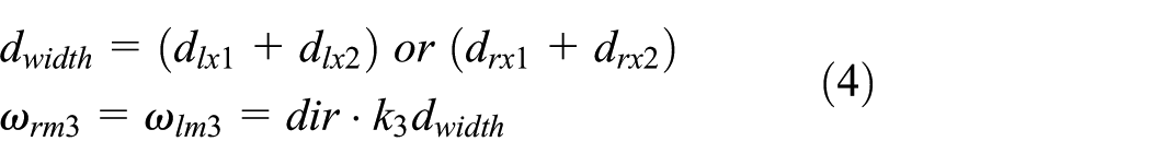
In equation (4), the step length is calculated by summing the distance between two feet at the moments of swing phase and landing phase. This calculated step length is applied to motor with moving direction (dir). Proportional gain (k3) was set to 10 r/min/pixel, the same as the value used in feedback control using stereo cameras.
Weighting factors for rotational walking

Finally, as shown in equation (5), all the control signals from pelvis motion sensors and stereo cameras are applied to wheel motors in the walker. However, equation (5) should be modified since the feedback and feedforward controls using stereo cameras can only consider forward and backward walking. It is necessary to deactivate them when the user turns around. However, the feedback control using pelvis motion sensors on the pelvis supporter can easily track rotational walking. Thus, we additionally proposed weighting factors for three controls and adjust them during walking. Improved angular velocities of the wheel motors with weighting factors are as follows
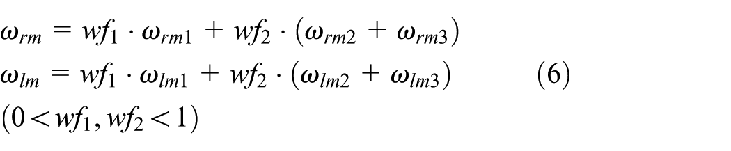
where wf1 and wf2 are determined by absolute angular difference
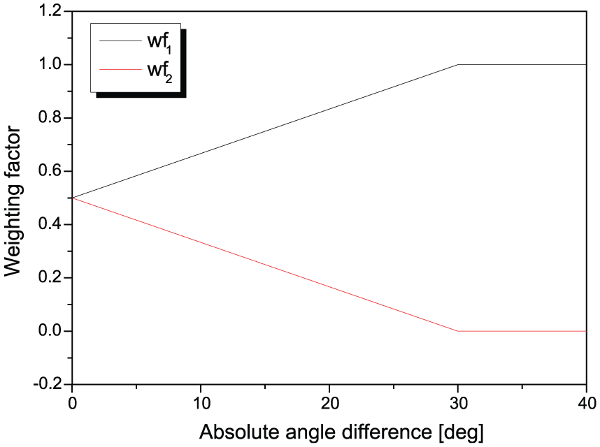
Weighting factors according to absolute angular difference
As shown in the block diagram of the final user-tracking control algorithm (Figure 13), the wheeled walker is operated by angular velocity inputs from the left and right wheel motors (ωrm and ωlm). There are two reference inputs: one is the angular displacement of the pelvis motion sensor and the other is the displacement of the user. The first reference input is zero all the time, but the second reference input varies freely. ωrm1 and ωlm1 are the control inputs to control θrp and θlp to be zero. ωm2 (= ωlm2 = ωrm2) is the feedback control input to compensate the difference between lower extremity position of user and wheeled walker. xR is the displacement of the walker, and xH is the user’s displacement. ωm2 is applied to both left and right wheel motors with the same value. ωm3 (= ωlm3 = ωrm3) is the feedforward control input determined by walking pattern analysis and also applied to both left and right wheel motors such as ωm2.

Control block diagram.
User-tracking experiment
Three different experiments were conducted to test the developed walker’s performance. Quantitative assessment was done to represent user-tracking performance.
User-tracking experiment using pelvis motion sensors
First, feedback control using pelvis motion sensors on the pelvis supporter was used to check whether the walker is able to track users’ walking. Angle trajectories of the right and left pelvis motion sensors were obtained during forward and backward walking (Figure 14). In forward walking, rotational angle of the pelvis motion sensor is in the range of 10°–20° (rms = 15.02°), which indicates that the walker tracks user with 70-mm distance between the pelvis and the walker on average. Rotational angle during backward walking is from −10° to −20° (rms = 15.26°) with 78-mm distance between the pelvis and the walker on average. The location of knee and ankle marker was collected using stereo cameras during walking (Figure 15). Smaller rms value of knee and ankle marker trajectories means that the walker follows user promptly. In forward walking based on control algorithm using pelvis motion sensors, the rms values of averaged knee and ankle marker trajectories were 46.95 and 74.93 pixel, respectively. In backward walking, the rms values were 78.83 and 78.61 pixel, respectively (note that 100 pixel ≅ 60 mm).

Pelvis motion sensor trajectories during walking.
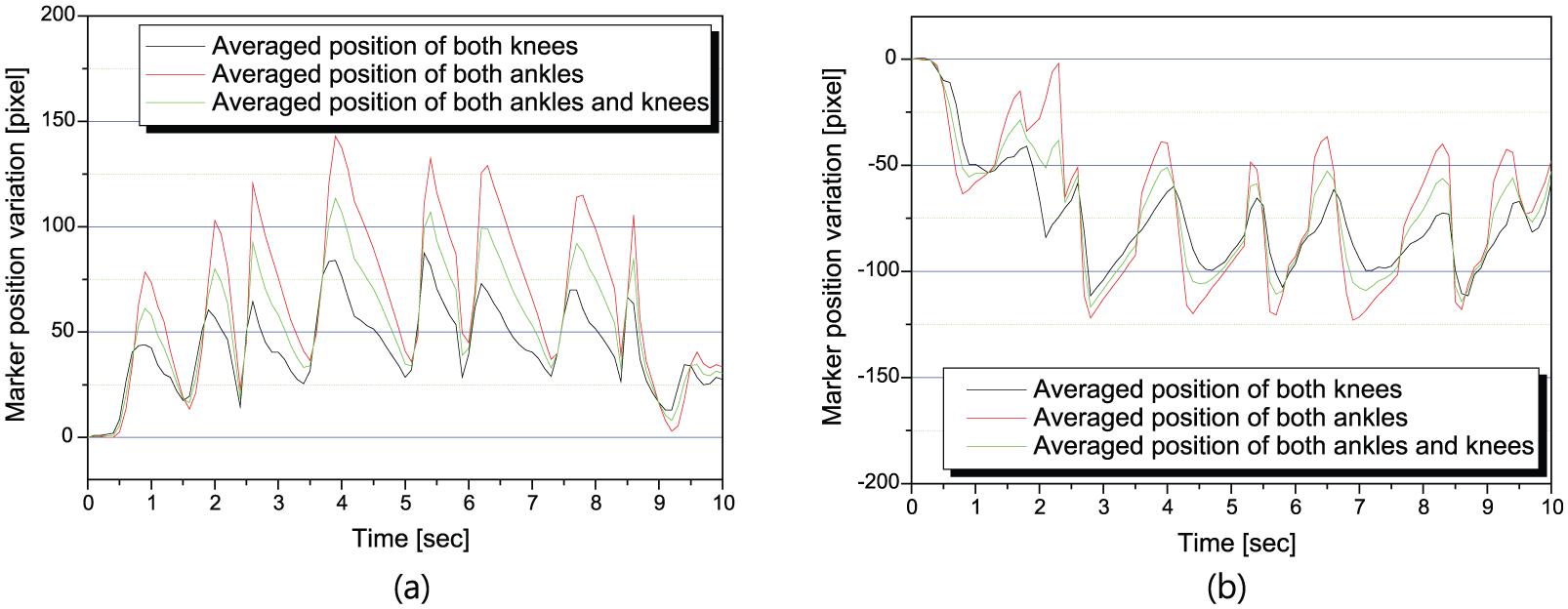
Averaged marker position trajectories during walking: (a) forward walking and (b) backward walking.
User-tracking experiment using both pelvis motion sensors and stereo cameras
Rotational angular displacements were recorded during forward and backward walking with feedback control using pelvis motion sensors and feedback/feedforward control using stereo cameras (Figures 16 and 17). In forward walking, the rms values of pelvis motion sensor angles was 9.53°, and the rms values during backward walking was 7.61°. These rms values indicate that the distance between the walker and the user’s pelvis is approximately 49 mm in forward walking and 39 mm in backward walking. These values represent the improved user-tracking performance compared to only using pelvis motion sensors by approximately 43%. The rms values of knee and ankle location trajectories during forward walking were 24.4 and 50.44 pixel (= 14.6, 30.26 mm), respectively. In backward walking, those values were 38.24 and 40.66 pixel (= 22.9, 24.4 mm), respectively. These values were reduced by approximately 45% compared to using only motion sensors indicating that the developed walker tracks user’s walking quickly and more accurately than previous control system. The summary of rms values for two different walking experiments is provided in Table 1.
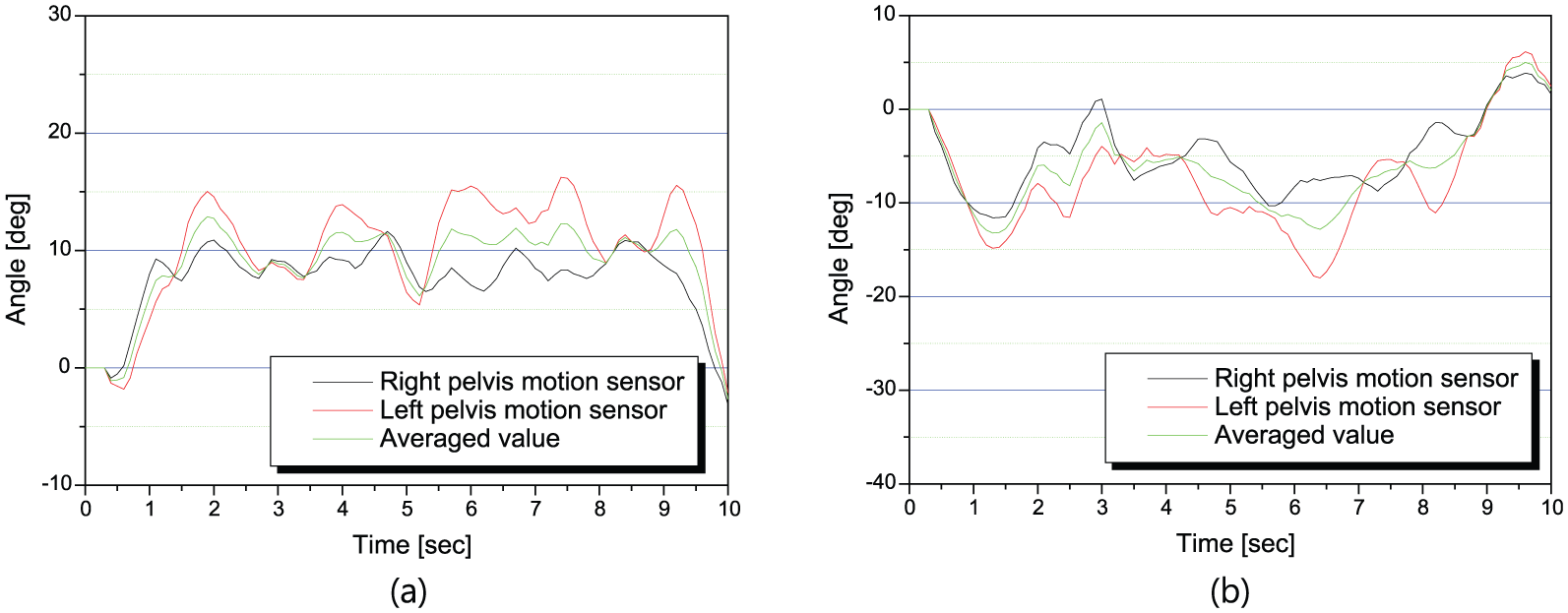
Pelvis motion sensor trajectories during walking: (a) forward walking and (b) backward walking.

Averaged marker position trajectories during walking: (a) forward walking and (b) backward walking.
RMS values during walking experiments.
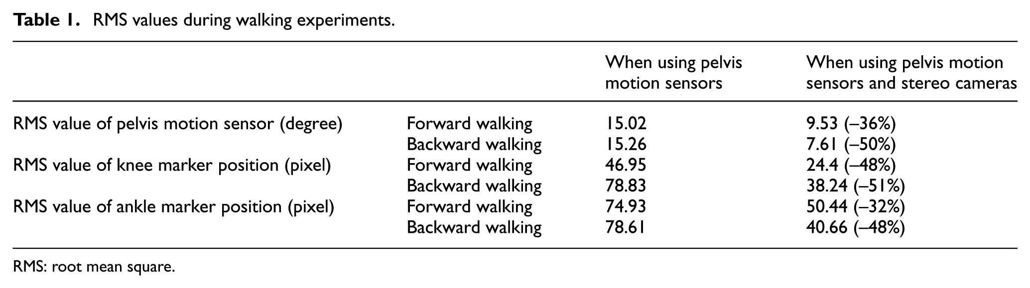
RMS: root mean square.
User-tracking experiment for rotational walking
Finally, rotational walking algorithm using weighting factors was applied to assess the walker’s user-tracking performance during turning around. First, the walker’s location was recorded without change in control weighting factor during user’s rotational walking. The walker’s rotational angular displacements are calculated as follows

where encl and encr are the encoder values of the left and right wheel motors, respectively; ratioreducer is the reduction gear ratio considering a reducer and a timing pulley; and lwidth is the wheel width of the walker. Walker’s moving displacement is computed using the difference between encl and encr, and the walker’s rotational angle is calculated using the moving distance of each wheel obtained in equation (7). Performance improvement by change in weighting factor during rotational walking is shown in Figure 18, which represents faster reaching time to 90°. Snapshots of forward, backward, and rotational walking are presented in Figure 19.

90° rotational movement of the walker.

Snapshots of the waking experiments: (a) forward walking, (b) backward walking, and (c) turn-around walking.
Muscle strength measurement using EMG
Required muscle strength to drive the developed powered wheeled walker and conventional passive wheeled walker was measured using EMG (Pocket EMG, BTS Engineering). For both walkers, user’s muscle strength in arms and legs (i.e. middle deltoid, soleus, and vastus lateralis) was recorded and compared during 15-s forward walking.
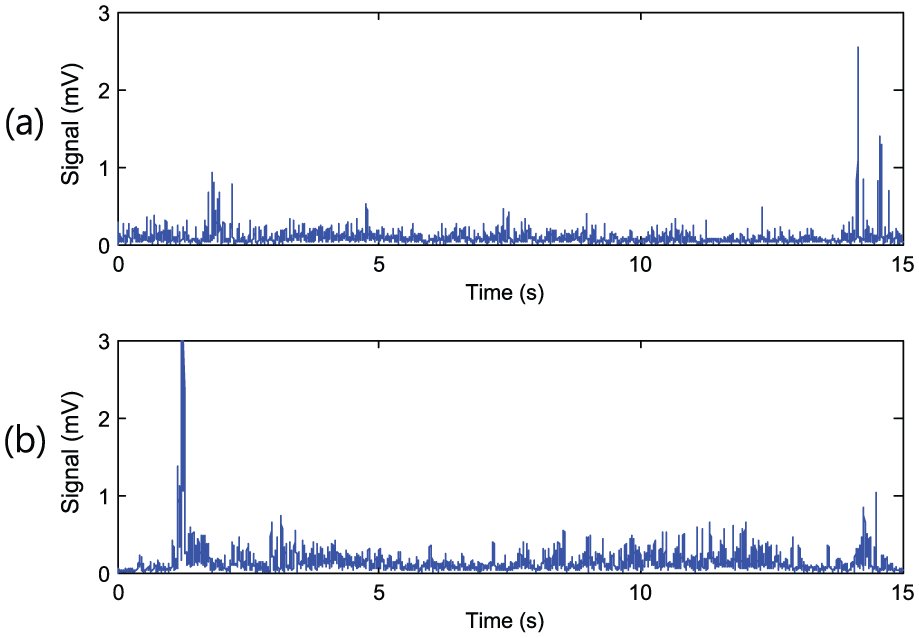
First, we measured soleus muscles of both legs that is essential for stable standing posture and walking. Figure 20 shows the EMG signals of soleus muscles’ exertion to drive a conventional walker and the developed walker. It can be seen that the developed walker decreased dramatically (77.2% on average) required muscle strength.

Comparison of EMG signals of soleus muscles between a conventional wheeled walker and the developed walker: (a) right and (b) left.
Second, muscle exertion of vastus lateralis in both legs used to lift knee during walking was assessed. When using a conventional wheeled walker and the developed walker, vastus lateralis muscle exertion was recorded using EMG (Figure 21). Differently from soleus muscle, there was no significant difference between two apparatuses. This result is reasonable because the developed walker does not support lifting of the legs.
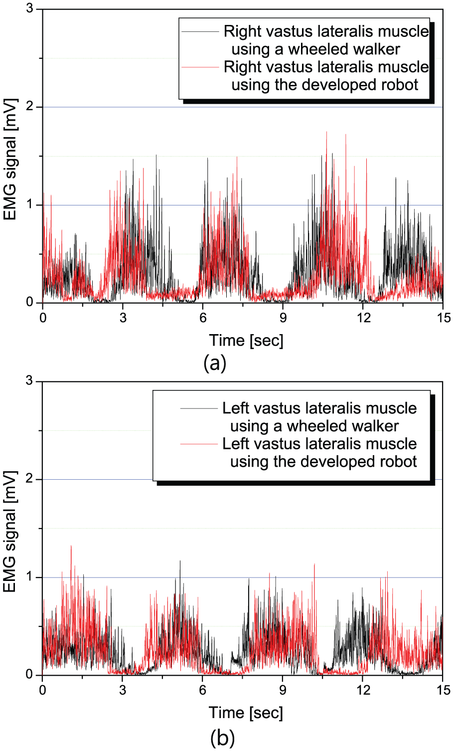
Comparison of EMG signals of vastus lateralis muscles between a conventional wheeled walker and the developed walker: (a) right and (b) left.
Finally, the required strength of middle deltoid of both arms during walking with a conventional walker and the developed walker was examined to measure the applied load to arm during walking. When using two devices, middle deltoid muscle exertion was recorded using EMG (Figures 22 and 23). The developed walker significantly reduced required middle deltoid muscle strength because it sufficiently supported the user’s weight by the pelvis supporter.

EMG signals of middle deltoid muscle using a conventional wheeled walker: (a) right arm and (b) left arm.
EMG signals of middle deltoid muscle using the developed walker: (a) right arm and (b) left arm.
Conclusion
We have developed a powered wheeled walker to help people with gait impairment rehabilitate safely. Based on the author’s previous study,17,18 the algorithm that the walker recognizes user’s walking will by pelvis motion and track user’s walking path efficiently was developed. In addition, a feedback/feedforward control algorithm using stereo cameras and an algorithm to change in weighting factors of controls for smooth rotational walking have been developed. User-tracking and muscle assistive performance of the proposed control algorithm was verified by actual walking experiments and muscle strength measurement using EMG successfully. An advantage of our method is to track the user effectively through a simple control algorithm without considering the dynamics of the user and the powered wheeled walker.
As the future work, we plan to install a mono camera in front of the user in order to minimize walker width. In addition, a variable pelvis supporter that can freely move in lateral direction will be added for smoother walking. For accurate tracking performance evaluation, we will try to measure the displacements of the user and the wheeled walker through an optical motion capture system.
Footnotes
Academic Editor: Yangmin Li
Declaration of conflicting interests
The author(s) declared no potential conflicts of interest with respect to the research, authorship, and/or publication of this article.
Funding
The author(s) received no financial support for the research, authorship, and/or publication of this article.