
Abstract
This article improves an enhanced predictor–corrector entry guidance method for hypersonic flight vehicle. To compensate for the shortcoming that the enhanced predictor–corrector guidance method sacrifices guidance precision to meet path constraints, this article develops an improved predictor–corrector guidance method. Through consuming more energy in the middle section of entry, the guidance method greatly reduces the load in the end section of entry, earning more time for the guidance bank angle which aims at ensuring entry precision to function in the end section, and thus, the entry precision is improved. The simulation results on the CAV-H flight vehicle show preliminarily that the guidance method effectively enhances the guidance precision for both orbital and suborbital entry missions and strictly constrains distance errors within the stipulated range. Furthermore, this method is also fairly effective for flight vehicles with lower lift-to-drag ratio (X-33). Then, the flight vehicle with a higher lift-to-drag ratio is chosen as the simulation target to further examine the guidance method’s effectiveness and precision.
Introduction
Entry flight of hypersonic flight vehicle is quite a demanding task due to the high speed and long distance flying which lead to large load, heat, and dynamic pressure. Thus, how to guide hypersonic flight vehicle to fly along a reasonable trajectory to guarantee entry precision and other process constraints is crucial in the whole entry. Recent years saw the rise of the predictor–corrector entry that has advantages in many aspects than the conventional trajectory-planning method.
Predictor–corrector entry guidance method derives from the onboard trajectory planning which does not need to pre-design a reference trajectory. This further leads to its advantages such as greater flexibility in reducing dispersions and the uncertainty of initial and terminal entry conditions. Most of predictor–corrector algorithms are less sophisticated and require less memory space for the onboard computer. Due to the above merits, this method has gone through a great and chronological development. Gamble et al., 1 Braun and Powell, 2 Powell, 3 Fuhry, 4 Kaluzhskikh and Sikharulidze, 5 Putnam et al., 6 Lu, 7 and Brunner and Lu 8 present a series of representative literatures studying in predictor–corrector entry guidance method. All these methods base on a similar fundamental algorithm which is to eliminate the errors of range-to-go in every guidance cycle, while their differences mainly lie in the ways when they deal with the path constraints and other details.
In spite of the advantages of predictor–corrector method, there is a long-standing shortage which is the lack of effective and widely applicable means to integrate inequality trajectory constraints into guidance algorithm (such as those on the heating rate and aerodynamic load). This shortage confines the application of this method to low-lifting entry vehicles. Xue and Lu 9 and Lu 10 aim at compensating for this shortage. In Xue and Lu, 9 a constrained predictor–corrector guidance method is developed. It introduces the upper and lower bounds for the magnitude of the bank angle into the guidance method by resorting to quasi-equilibrium glide condition (QEGC), without increasing the complexity of the algorithm and decreasing the robustness. Lu 10 presents a unified entry guidance method, on which this article is mainly based on. The unified method further overcomes the problem of enforcing path constraints and makes it viable in both orbital and suborbital entry missions. Plus, the method from Lu 10 is more robust and widely applicable; it is a rather new method which can resolve the extant problem satisfactorily.
While Liu et al., 11 and Wang et al.12,13 all mainly derive from the guidance logic from Xue and Lu 9 and Lu, 10 they make their own contribution to addressing problems not discussed in Xue and Lu 9 and Lu. 10 For instance, Liu et al. 11 focus on altitude control; it increases altitude precision while allowing for the path constraints and other terminal conditions simultaneously. Wang et al. 12 combine Xue and Lu 9 and Lu 10 and develop an entry guidance method which could also be used for high-lifting hypersonic vehicles and reduce trajectory oscillations effectively.
Li et al. 14 take perturbation of the atmospheric density and aerodynamic parameters into consideration and resorts to Kalman filter to develop an adaptive predictor–corrector guidance law which is able to decrease the influence of these perturbations. Gu et al. 15 further use adaptive controller to suppress trajectory oscillations.
Adaptive controller can resist uncertainties of the model and increases the robustness of the entry process; yet, it requires more computing capability which will burden the structure design of hypersonic flight vehicles. Methods which share the same basic logic as Xue and Lu 9 and Lu 10 need much less calculation and have to great potential to be put in practical use. Between the two, the unified entry guidance method designed in Lu 10 is superior in adaptiveness and calculation.
This article presents an improved predictor–corrector entry guidance method on the basis of Lu. 10 As in the process of utilizing the method proposed by Lu, 10 the method’s shortcoming of sacrificing the entry precision to meet the path constraints is revealed; thus, this article aims at proposing an improved method to compensate for this shortcoming. First, the basic entry guidance method will be introduced and then the method in Lu 10 will be presented briefly in order to give rise to further discussion on this method. Then, the improved method is developed by taking the general characteristics of entry trajectory into consideration to overcome the method’s shortage. Simulation tests are carried out and the results show the improved method could promote the entry precision effectively while the path constraints are met and the merits of previous method remain.
The entry problem
Dimensionless 3-DOF equations of motion
The dimensionless 3-degree of freedom (DOF) equations of entry motion for entry vehicles are as follows 16


where
The entry constraints
The path constraints
The typical trajectory inequality entry path constraints include heating rate, load, and dynamic pressure, 9 which are expressed as equations (7)–(9)


where
The entry terminal constraints
The entry mission requires the flight vehicle to meet not only the above path constraints but also a series of entry terminal constraints at the terminal area energy management (TAEM) interface. They include terminal energy constraint, altitude constraint, velocity constraint and entry distance constraint, and so on. One important constraint is distance constraint

where

The improved predictor–corrector method
As the lateral guidance is only used to determine the symbol of bank angle so as to keep the flight vehicle’s boresight error within the pre-set boundary and it is simple and mature, this article focuses on the longitudinal guidance method. The development of improved guidance method is based on the method in Lu, 10 which we call the enhanced predictor–corrector method in this article. First, the enhanced method is to be introduced briefly and discussed.
The enhanced entry guidance method
Lu 10 presents a guidance method, which is based on the basic predictor–corrector guidance method and then enhanced with its algorithm by introducing feedback items, thus called the enhanced entry guidance method. The basic predictor–corrector method calculates each moment that can enable the entry vehicle’s terminal distance to meet its constraint (see Brunner and Lu 8 for details on its principles).
In each guidance cycle,

where
Feedback compensation items for balanced glide
First, the concept of QEGC is introduced to eliminate the oscillations of the altitude profile to make the entry trajectory smoother. The definition of QEGC is that the vehicle’s flight path angle and its change rate are approximately zero during entry process:

where

Equation (12) can be expressed as

The QEGC feedback item
Load and heating rate feedback items
Take the load constraint in equation (8) as an example.

And equation (17) is obtained
To meet load constraint, each position along the entry trajectory requires the following


Thus, the use of the guidance command in equation (19) can help implement the above three constraints.
The improvement on enhanced method
The shortcomings of enhanced predictor–corrector guidance method
We take generic high performance Common Aero Vehicle (CAV-H) as the simulation model and use the enhanced method to analyze the simulation results. Its entry heating rate constraint is
Simulating entry missions.

In Table 1,
The amplified end section of load curves for orbital entry.

The amplified end section of load curves for suborbital entry.
The figures show that the guidance law with QEGC item makes the curve smoother and the heating and load item constrains the load at the end section of entry where there is a tendency that the load exceeds its constraints, thus enabling the load to stabilize under the constraint (1.8 g). This is also true for suborbital entry mission, as shown in Figure 2.
The figures show that there is an overall trend that the changes in both orbital entry and suborbital entry loads gradually increase. When the heat flow load item is not used, the load at the end section of entry may exceed a constraint value. Therefore, the time when the load item functions is mainly during the end section of entry, while the heating rate operator
Although both the QEGC item and the heating rate and load item are introduced on the basis of equation (12), the selection of the
The above characteristics of the enhanced predictor–corrector guidance method and the characteristics of entry trajectory that result from the use of this guidance method bring about the following problems.
Improving the enhanced predictor–corrector guidance method
To solve the above problems of the enhanced guidance law, we develop an improved predictor–corrector guidance method according to general characteristics of entry trajectory. First of all, QEGC item mainly functions at the initial entry stage; the heating rate item functions mainly during a small period of time in the middle section of entry. Thus, the compensation item
Second, during the entry, the larger the bank angle of the entry vehicle is, the faster its altitude drops and consequently the faster its kinetic energy decreases as the flight vehicle receives greater aerodynamic drag during the subsequent entry. According to the observation of entry process under the enhanced guidance method, the compensation item does not function during most of the time in the middle section of entry. Plus, the middle section of entry has a rather weak influence on entry precision. Therefore, it is feasible to take advantage of the middle entry part to consume more kinetic energy.
Consequently, the starting point for improving the enhanced guidance law is to try to enable the flight vehicle to increase its bank angle in order to consume more energy during the middle section and to reserve enough time for the end section which has larger influence on entry precision to execute the bank angle based on the entry precision (
After the entry starts, at the moment
In guidance algorithm, the flight vehicle carries out its entry flight with bank angle
After the flight vehicle’s load value reaches
The guidance algorithm is to find the bank angle

Meanwhile,

Comparing the orbital entry load curves.

Comparing the orbital entry altitude curves.
Comparing the orbital entry bank angle curves.
The simulation results on suborbital entry mission, given in Figures 6–8, show that the improved guidance method is still applicable to suborbital entry mission, and that the general characteristics of altitude curve and bank angle curve agree with those for orbital entry mission. The only obvious difference is that because the conditions for suborbital entry mission are harsher (the vehicle is required to consume great energy in a shorter period of time), the time for consuming energy in the middle section of entry is shorter than that in orbital entry. Although it is not as obvious as it is in orbital entry mission from the figures, the improved guidance method effectively reduces the load in the end section of entry and yet tremendously enhances entry precision in suborbital missions.
Comparing suborbital entry altitude curves.

Comparing suborbital entry load curves.

Comparing suborbital entry bank angle curves.
To quantitatively investigate the improved predictor–corrector guidance method, we establish a set of suborbital entry missions whose initial conditions for entry (such as initial longitude and latitude) and entry distances are different while whose terminal conditions are the same (all at longitude 279.504°, latitude 28.611°) (see Table 2 for details). All the initial altitudes are 60 km; the initial velocities are 7000 m/s. The distance error range in the end of entry is required to be 9.27 km.
The initial longitudes and latitudes and entry distances of entry missions.

Table 3 shows that with the enhanced predictor–corrector guidance method, the distance error in the end section of entry often exceeds the stipulated distance error range of 9.72 km. This is because the enhanced method makes the bank angle focus on reducing load to meet load constraints and unable to guarantee entry precision in time before end of entry. Table 3 also shows that with the improved guidance method, the error at TAEM interface greatly decreases, thus being able to fully satisfy given distance error ranges. Comparing the two methods, the improved method improves the precision by 68.79% averagely for the six entry missions.
Distance error for CAV-H with the enhanced and improved guidance method.
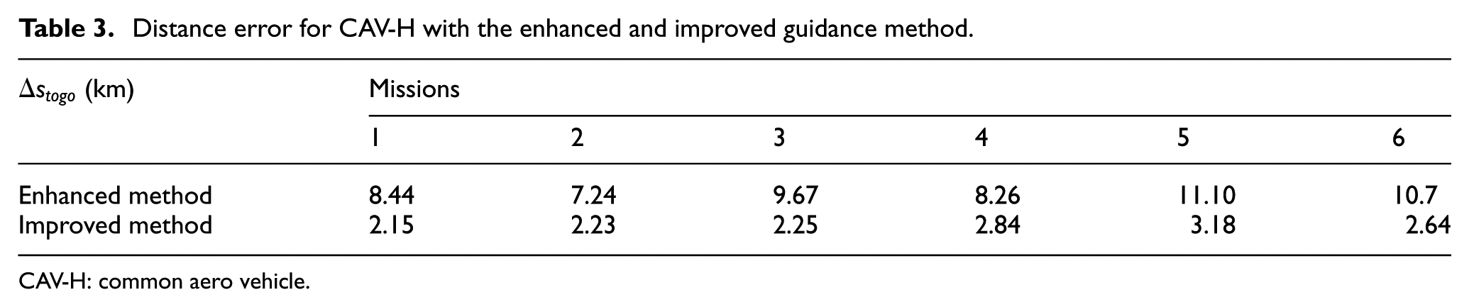
CAV-H: common aero vehicle.
The above simulation results show that even if the CAV-H flight vehicle faces suborbital entry missions, the improved guidance method can still effectively reduce its distance error. To further test the extent of the method’s applicability, we should examine whether it is applicable to the entry flight vehicle that has a larger lift-to-drag ratio. Because the larger the lift-to-drag ratio is, then the larger the load value in the end section of entry is, the longer time the heating and load item functions, and the greater influence it exerts on entry precision.
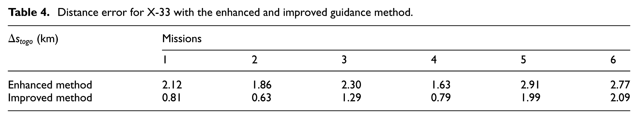
As the enhanced guidance method is effective to be applied to flight vehicles with different lift-to-drag ratios, the versatility of improved guidance method should also be examined. Thus, we choose X-33 to test the applicability of improved guidance method to flight vehicles with lower lift-to-drag ratio. Simulation conditions are as same as previous ones except that X-33’s heating rate constraint is
According to Table 4, the improved method improves the precision by 46.62% averagely for the six entry missions. We can still see errors are reduced fairly well under the improved method, even though entry distance errors of flight vehicles with lower lift-to-drag ratios are already low enough under the enhanced method. Thus, the improved guidance method proves to be versatile enough to be applied to different flight vehicles.
Distance error for X-33 with the enhanced and improved guidance method.
We then look at the simulation results by factitiously increasing the lift-to-drag ratio of CAV-H by 0.2 time.Figure 9 shows that for the flight vehicle with a higher lift-to-drag ratio, the improved guidance method is still effective in orbital entry mission, and that its load curve in the end section of entry is much smaller than that of the enhanced predictor–corrector guidance method. The former method creates enough time for the bank angle to control entry precision and still contains the entry error effectively. However, the difference for suborbital entry mission is not that clear to see (see Figure 10 for detail).

Orbital entry load curves for the flight vehicle that has a higher lift-to-drag ratio.

Suborbital entry load curves for the flight vehicle that has a higher lift-to-drag ratio.
Table 5 shows that as the lift-to-drag ratio increases, the distance error in the end section of entry increases with the enhanced guidance method. However, the improved method increases the precision to a very limited degree (averagely 21.43%) and does not effectively constrain it within the stipulated scope. The reason is that the suborbital entry mission leaves a much shorter middle section for the flight vehicle to consume energy than orbital entry mission. Furthermore, because of the higher lift-to-drag ratio of the flight vehicle, the middle section of entry becomes even shorter, limiting the effectiveness of the guidance method. This problem needs to be further resolved.
The distance errors for the flight vehicle with higher lift-to-drag ratio.

Conclusion
This article proposes an improved predictor–corrector guidance method which compensates for the shortcoming of enhanced predictor–corrector guidance method that the distance precision at TAEM interface for the entry vehicle could not be guaranteed under some demanding entry conditions. The main idea of improved method is to use the middle section of entry to consume a large quantity of energy and to ensure that the load value decreases to a sufficiently small degree, thus enhancing entry precision.
Then the guidance method is used to simulate the orbital and suborbital entry missions of the CAV-H flight vehicle. The guidance law is quite effective and can effectively increase entry precision and satisfy entry distance requirements. To test whether it inherits the versatility of enhanced guidance method, we use X-33 as a low lift-to-drag flight model to carry out simulations. The results show that the method is also applicable under this circumstance. This shows that this method compensates for the disadvantage of enhanced guidance method with preserving its advantage without increasing too much computing burden.
To further investigate the applicability of the guidance method, we factitiously raise the lift-to-drag ratio of CAV-H. The simulation results show that the distance error of orbital entry mission can still be strictly controlled, while that of suborbital entry mission cannot be effectively constrained within the stipulated scope which needs to be further resolved.
Footnotes
Academic Editor: Anand Thite
Declaration of conflicting interests
The author(s) declared no potential conflicts of interest with respect to the research, authorship, and/or publication of this article.
Funding
The author(s) disclosed receipt of the following financial support for the research, authorship, and/or publication of this article: This work was supported by the National Natural Science Foundation of China (grant nos 61104195 and 6150330).