
Abstract
Tolerance has great impact on the cost and quality of a product. This article proposed a dimensional precision measurement method for the shaft and the flange in motorized spindle and designed a special instrument for this purpose. First, the measured dimension errors and problems were analyzed, which has two geometrical dimensions. Second, the measuring methods for them were proposed. A three-stepped plug gauge and coloring method were applied to measure the first dimensional precision. The second dimensional precision, as in space dimension, is the distance from the flange end face to intersection line of tapered surface and inner bore surface and was converted into the distance from the end face to the tangent point between a ball and tapered surface and then was measured with a simple method. Mathematical derivation was conducted and then a simple mathematical model was applied to map the relationship between these two distances. Self-centering principle and structure were designed to improve the positional accuracy of gauge. Third, according to the proposed dimensional precision measuring method, a composite instrument was designed, which can measure the two required geometrical dimensional precision of shaft and flange. Finally, the manufactured instrument was applied to actual production process, and the results validated the effectiveness and correctness of the proposed method.
Introduction
The high-speed motorized spindle is one of the core components of high-speed computer numerical control, and its operating characteristics influence extremely on the machining precision of parts and processing efficiency of machine tools.1–3 The shaft is a key part of the motorized spindle. The dimensional precision of the shaft plays a decisive role in the final performance of motorized spindle because many parts, such as flange, motor rotor, and bearings, are mounted on it. 4 Therefore, how to ensure the dimensional precision of the shaft with other parts and improve the measurement efficiency is a very critical issue. Good measuring method and device can effectively guarantee the dimensional precision of parts and improve processing efficiency, and many scholars have done much effort at this research field.5–11 Various research efforts considered with different aspects of dimensional precision may have different advantages and applications. This article focuses on the dimensional precision between the shaft and the flange and studied the measuring method and integrated measuring instrument of dimensional tolerance to ensure the critical dimensional precision of the shaft and the flange.
The motorized spindle in this article is applied in high-speed machining center. In order to improve the production efficiency, the machining center is designed to exchange tools automatically in one process to reduce the machining time. Consequently, the shaft is designed as a hollow shaft, to be equipped with broach mechanism and HSK shank, and its inner taper hole is 1:10. The HSK shank uses the inner conical face and the end face to locate the position at the same time. In order to ensure the normal operation of the shank and the broach mechanism, the key dimensional tolerances of flange with shank, shaft, and broach mechanism must be guaranteed.
A dedicated gauge to measure the dimensional precision between flanges, broach institutions, shank, and shaft is needed. Therefore, for this engineering challenge, this article first analyzed the required measuring dimensional precision between them and identified measurement difficulties and then studied the measuring principle for the dimensional precision and proposed an effective method for these issues. Furthermore, it designed a reliable dedicated gauge according to the proposed method. Finally, the dedicated gauge has been manufactured and applied to actual production.
Problem analysis
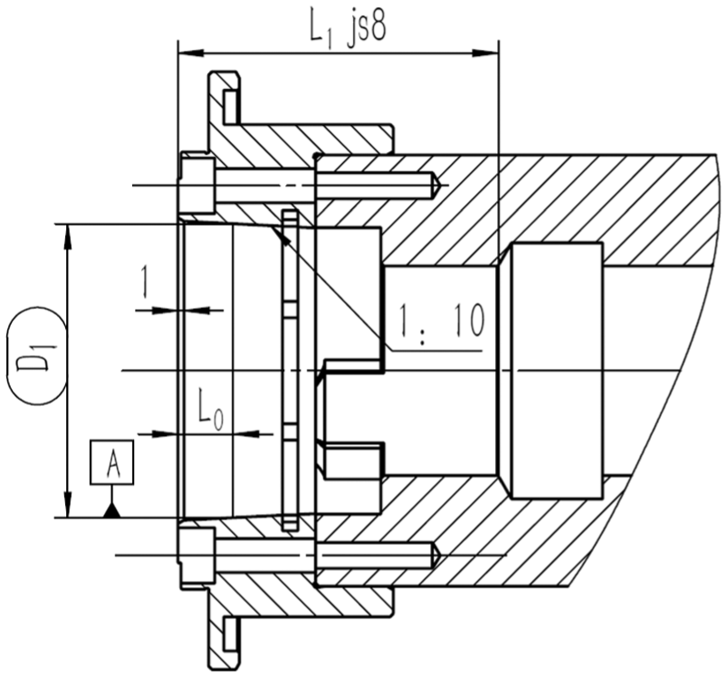
The motorized spindle is equipped with broach institution and shank. In order to ensure the final performance, it needs not only to meet the dimension of shank, that is, its diameter is D1 when the distance is L0 from the end surface to it, but also to satisfy the dimensional precision of L1js8, as shown in Figure 1. And the L1js8 is measured after the shaft is assembled with flange. However, as this dimension is a spatial dimension, it is difficult to measure with common measuring tools. To greatly improve the efficiency of production and ensure these dimensional precision, this article proposed a measuring method and designed a dedicated instrument, which can measure these required dimensions.
Assembly drawing of shaft and flange.
Figure 1 is the assembly drawing of shaft and flange, and the required measuring dimensions are as follows:
For 1:10 conical surface of flange, its diameter is D1 when the distance is L0 from the end surface of flange.
Dimensional precision of L1js8.
For the first measuring requirement, it can be detected with coloring method. A plug gauge coated with pigments is inserted into the flange bore, and then is rotated around. Then the inner hole’ coloring rate is observed. If it is more than 90%, the conical surface of flange passes; otherwise, the conical surface of flange fails.
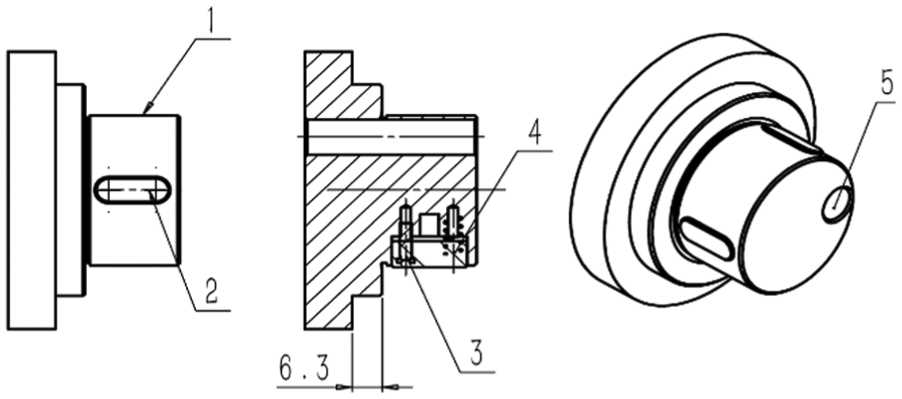
The second dimensional precision of L1js8, as shown in Figure 2, is to satisfy the requirement of the shank clamping unit assembled with the shaft, and it is important for the performance of motorized spindle. However, this dimension is the distance from the flange end surface to intersection line of α tapered surface and inner bore surface. The diameter of inner bore surface is D2. As a spatial dimension, the second dimensional precision is difficult to measure with common measuring tools. Therefore, it is necessary to design a special gauge, to meet the measurement requirements, while meeting the efficiency measurement of the mass production.

Enlarged view of measurement object:(a) measurement object and (b) enlarged view.1: flange; 2: shaft.
Measuring method
Measuring method of flange
According to the analysis in above sections, the following solutions were designed to measure the first dimension. As shown in Figure 3, a three steps plug gauge was designed. The first step is axial positioning surface. The second step is a cylinder with L0 length and D1 diameter, and its ring surface is coated with pigments. The flange grinding process is as follows: coarse grind, insert the plug gauge into the inner bore surface of flange, rotate the gauge, and check the coloring rate of inner hole and the gap between the first step and the end face of flange by feeler. If the coloring rate is above 90% and the gap is within the required tolerance range, the first dimension is ok. The third step is taking a cylinder with diameter less than D2 mm, as a self-centering cylindrical surface (described in section “self-centering design principles”).

Measure solution of the first dimensional precision.
Measuring method of assembly dimensional precision of flange and shaft
Measuring principle analysis and design
The second dimensional precision is a distance from the flange end surface to intersection line of α° tapered surface and D2 inner bore surface. The tolerance of length dimension is L1js8. In Figure 4(a), L1 is the required dimension to be measured. If using common measuring tools, such as calipers, micrometers, and coordinate measuring machines, it would be inconvenient because of their structural characteristics limitation. So it is necessary to design a special measuring tool to measure this dimensional precision quickly and easily.

Measuring principle: (a) measured dimension and(b) geometric diagram of measured dimension.
For this type of problem, this article proposes a method to measure the distance from the flange end surface to intersection line of tapered surface and inner bore surface for mass production, as shown in Figure 4. As shown in Figure 4(a), a spherical ball is tangent to a α° tapered surface, and the contact point is marked as point A, steel ball diameter marked as r, and distance from contact point to end face of flange marked as L2. And the ball center is labeled as point O1(x, y). Therefore, the relationship between L1 and L2 is as follows


Based on the above analysis, if
Through the point A, draw a line AB perpendicular to the X-axis. The vertical line AB intersects with the horizontal line O1B at point B, then AB and O1B is


The extension line of the generatrix of the inner cylindrical surface intersects Y-axis at point E and then OE is


In equation (11), when the steel ball is installed and tangent to inner circular conical surface, y, R,

According to above analysis, a conclusion can be drawn that L1 is linear to L2, and the scale coefficient is 1. So the L1 that is difficult to measure can be transformed into measure L2. The dimension error of L1 can be measured by measuring L2.
Measuring method design
According to the design principle presented in the previous sections, L1 measurement is converted into L2 measurement. In order to make it easier to get the actual dimensional deviation, this article designs a dedicated measuring tool with a reference gauge. The inner cylinder hole diameter of the reference gauge is R, which is the same as measured object; the end face of reference gauge has a α° conical surface; the distance from the contact point between steel ball and conical surface to front-end face of the reference gauge is L2. The measurement process is as follows: first using the reference gauge to adjust the dial indicator to zero, then measuring the actual parts, and reading the actual dimensional error by the swing value of the needle. If the dimensional error is within the tolerance range, the part passes; otherwise, it fails.
Self-centering principle design
When measuring L2, the requirements of diameter runout that the α° conical surface with respect to reference A and reference B are 0.01 mm, as shown in Figure 2(b). Datum A is the centerline of the inner cone of flange. Datum B is the centerline of the inner hole at the end of shaft. The inner hole at the end of shaft is assembled with the clamping unit. Furthermore, the requirements of diameter runout that the required measured inner cylindrical surface with respect to reference A and reference B are also 0.01 mm. And in order to reduce measurement error, the center of measuring rod of measurement instrument should be concentric with the measured inner cylinder.
For this problem, this article proposes a self-centering principle, as shown in Figure 5(a), and the three equal forces F are evenly distributed of the circumference of the probe. According to the principles in Figure 5(a), this article designs a self-centering structure to ensure the measuring accuracy for gauge.

Self-centering principle: (a) evenly distributed force on the circumference of the probe and (b) three cambered surface and spring.
For the self-centering structure, the outer positioning cylinder of the measurement instrument should be in surface contact with the inner hole of measured shaft, according to the concentricity requirement between the gauge and the measured shaft during measurement process. The small clearance fit can achieve this requirement with some extent, but it will increase the difficulty for the probe to insert into the inner hole, and may even damage the workpiece surface. Therefore, this article proposes a method which uses a floating surface as the centering surface to contact with the inner hole of workpiece. And the contact surface is consisted of three cylindrical cambered surface; these three parts together form a positioning cylindrical surface, as shown in Figure 5(b). There is a same spring under every cambered surface. When measuring workpiece, these cambered surfaces can move at the diametrical direction under the pressure of springs. This method can not only to ensure the concentricity between gauge and workpiece, but also to easily do operation and measurement.
As shown in Figure 6, in the circumference of gauge, there are three keyways and some inner holes which are used to install springs, and also have threaded holes which are used to fix key. First, three flat keys are fixed in keyways respectively using the flat-head screws, and then they are as a part of the gauge and be grinded accompany with the gauge outer cylinder. Therefore, the outer surface of flat keys will have the same diameter and is concentric with outer surface of gauge. In order to make the gauge contact with inner hole of the measured shaft tightly, after grinding is completed, springs are installed under each key and fixed them by flat-head bolts. Six bolts are screwed into the same depth. It must be ensured that there have compression space for spring to adjust the radial dimension. This radial dimension is the diameter of cylindrical surface that constituted by three keys. This cylindrical surface is the working surface and makes the located block self-centering.

Self-centering structure.
Design of measuring instrument
According to the principle of the above sections, this article designed a special gauge to measure the assembly dimensional precision between the flange and the shaft, and its structure is shown in Figure 7. The instrument is mainly composed of dial indicator 1, clamping block 2, spacer 3, surveying rod 4, position block 5, and reference gauge with base 6. Position block 5 is concentric with reference gauge 6 and located on the reference gauge 6 through the steps of position block 5. There are three evenly distribution keyways along the circumference of the position block 5. Each keyway has two deep holes. One spring is under each key. Spacer 3 is above the position block 5, with a threaded hole and a through-hole. This through-hole is concentric with that of the position block 5. Clamping block 2 is above the spacer 3, fixed on spacer 3 through the countersunk head bolts. Dial indicator 1 and surveying rod 4 are installed respectively through the two through-holes of clamping block 2. Surveying rod 4 is a thin rod, installed in the eccentric hole, and front end of surveying rod 4 is the probe 10. The probe is with a ladder hole. There is a steel ball in the second step hole, which is pressed and fixed tightly through set screws. Reference gauge is fixed on the base by threaded.

Drawing of special measuring instrument of shaft and flange: (a) probe in the reference gauge and (b) probe out of the reference gauge.
Reference gauge
According to the problem analysis by section “Measuring method design,” it is necessary to design a reference gauge for zero calibration, as shown in Figure 8. The diameter of inner hole of the reference gauge is the same as the measured shaft. The reference gauge also has the same α° conical surface with the measured shaft. When zeroing the instrument, the front-end face of reference gauge should touch the first step surface of position block 5. When zeroing the instrument, the front-end surface of reference gauge should touch the first step surface of position block 5, and the steel ball of probe 10 is tangent to taper surface. The axial section diagram for reference gauge is shown in Figure 8.

Reference gauge.
Position block
The position block has three stepped surfaces with different diameters. There is an eccentric hole in first step surface, whose front-end surface contacts with the underside of spacer. And its underside surface is taken as a supporting plane firmly against the front-end surface of the measured flange. And the diameter of this step surface is bigger than others, so as to ensure the contact area between position block and flange, and to increase the stability of the measuring instrument. The length and dimension of the second step surface are calculated according to the dimensional precision of the taper of the measured flange, as shown in section “Measuring method of flange.” The diameter of the third step surface is a little smaller than that of the measured shaft. So it is easier for putting the probe into the reference gauge and the workpiece. In addition, in order to guarantee the rod rigidity, axial size of the third step is appropriately extended.
The third step can also realize self-centering function. The self-centering structure as shown in Figure 6 of section “Self-centering principle design” is set on the cylinder surface of third step. There are three keyways on the circumference of cylinder surface. Each keyway has two deep holes to mount springs. The keys installed on the spring and fixed by flat-head screws. Therefore, three keys are allowed to do radial movement during zeroing and measuring with spring force, thereby keep surface contact with the inner hole surface of shaft and to achieve automatic centering function, so as to guarantee the measuring instrument better concentric with measured parts and guarantee the accuracy of measurement. The structure of position block is shown in Figure 9.

Self-centering position block with three stepped surfaces.
Surveying rod, steel ball, probe
The surveying rod is a slender rod through the eccentric hole in the position block. The eccentric hole is convenience for rod to insert into the inner hole of workpiece and reference gauge. Without the eccentric hole, the probe will be unable to enter the inner hole of workpiece and reference gauge because the biggest diameter of probe is greater than inner hole’ diameter of the workpiece and reference gauge. The probe is the front end of rob, whose scalene cone is designed as 1/8 circumference of a circle, as shown in Figure 10(b). This design can meet the installation requirement of steel ball, and also can reduce rod's weight. There is a ladder through hole in the bottom of probe. The steel ball is set in the second step and fixed by set screw. Some part of the steel ball is exposed, which is used to be tangent with measured surface.
Installation and measurement of ball: (a) measurement status of the ball and (b) ball mounted on α° conical surface.
Clamping block
There are two through-holes and a thread hole in clamping block. And the clamping block is fixed on the spacer through the thread hole. In order to realize fast clamping and keep the rigid of the clamping part, there is a slender hole on each through-hole and also a countersunk head hole at side face. The length and diameter of clamping bock are calculated according to the dial indicator and survey rod.
Measuring instrument and measuring process
The measuring instrument photos are shown in Figure 11.

Instrument photos.
Measuring process of this instrument includes the following steps:
Step 1: Insert the surveying rod into the reference gauge and rotate it. When the indicator is at a minimum value, then adjust it to zero;
Step 2: After zeroing, rotate the probe to the position that is not interfere with inner hole surface of the reference gauge, and then slowly pull the probe out of the reference gauge;
Step 3: Rotate probe to the position that is not interfere with inner hole surface of the shaft, and then insert it into the shaft that will be measured;
Step 4: Rotate rod and record the value of dial indicator when the indicator is at the minimum value. According to formula (12), the measured value is the actual deviation.
Conclusion
This article studied the dimensional precision measurement of shaft and flange at the motorized spindle, analyzed the measuring principle and methods about the dimension tolerance between shaft and flange, and then proposed an easy and effective measurement method for this kind of challenge. A steel ball is installed on the cone which can convert the distance from the flange end surface to intersection line of tapered surface and inner bore surface to the distance between the end face and the tangent point. What is more, this article proposed a measuring rod self-centering principle and designed a self-centering instrument to ensure the accuracy of measurement. A special measuring instrument was designed and manufactured to measure the dimensional precision of shaft and flange of motorized spindle. The instrument has a compact structure with low cost. The measuring results proved that the instrument is effective and easy to operate.
Footnotes
Academic Editor: Francesco Massi
Declaration of conflicting interests
The author(s) declared no potential conflicts of interest with respect to the research, authorship, and/or publication of this article.
Funding
The author(s) disclosed receipt of the following financial support for the research, authorship, and/or publication of this article: This topic of research is supported by the National Natural Science Foundation of China (grant no. 51305251) and the key subject of Shanghai Polytechnic University (Material Science and Engineering, XXKZD1601).