
Abstract
Sheet metal with micro-groove on its surface has following advantages, such as lightweight, high wear resistance, and drag function, and is hence widely used in various applications. Currently, there are a series of methods to process micro-groove, but those methods are not used in mass production. In this article, roll-to-roll sheet forming method preheated to elevated temperatures has been discussed and shown to produce micro-structure with better shape and height, in addition to aiding the possibility of continuous production. The influence of rolling micro-groove is studied numerically using the software Deform-3D. Temperature, grain size, geometry, rolling load, size, and height of micro-grooves have been discussed. The results show that the temperatures, widths of the groove, and radius of top and bottom fillets have significant influence on the forming process. At the same time, the experiments prove the feasibility of heated rolling micro-groove on surface of sheet metal.
Introduction
An enhancement of product functionality had been developed by specific functional surface structures with micro-structure.1,2 Micro-structured surface can also improve ecologic aspects in production processes and reduce the resistance of material, improving wear resistance and mechanical properties. Several authors3–5 reported using special biological surface micro-structures with super-oleophobic characteristics, solved the problems associated with oil adhering to pipeline surfaces, and subsequently contributed to reducing the marine oil pollution. Extensive studies6–8 have been conducted using ribs to minimize the drag reduction and to enhance the self-cleaning ability by carefully controlling the micro-structures and rib geometry on the surface of these marine objects. Ribs with symmetric v-grooves (height equal to spacing) with adhesive backed film manufactured by the 3M company (USA) have been widely investigated in most earlier work and the results have revealed enormous consistency with regard to the degree of drag reduction as well as maximum viscous drag reduction in the range of 4%–8% has been measured on a variety of two-dimensional flows with zero or mild pressure gradients; 6 some of the earlier studies, for example, Walsh, 9 at low speeds have focused attention on optimizing ribs geometry and drag reduction as high as 10% have been reported.
In order to let the micro-structure play an important role, many process methods have been developed such as ultra-precision fly cutting, laser shock forming, ion etching, and LIGA. SJ Zhang et al. 10 proposed ultra-precision fly cutting; this process method offers the highest flexibility necessary for fabricating freeform, micro/nano-structural surfaces, as well as hybrid structural surfaces with sub-micrometric form error and nanometric surface roughness, and its constant cutting velocity provides uniform high surface quality. However, fly cutting intermittent cutting process results in distinctive surface generation mechanisms and surface material separation and deformation. 11 Laser shock forming is a non-thermal laser forming method using the shock wave induced by laser irradiation to modify the curvature of the target.12,13 Currently, a femtosecond laser is applied in laser cutting, also. Some thin sheets are cut into complicated shapes and bent by femtosecond laser. 14 However, laser setup having high cost and low efficiency has limited its application broadly. Ion etching and LIGA employs deep X-ray lithography and electrodeposition to produce small metal or plastic parts having lateral dimensions up to several centimeters and feature sizes down to 1 μm or less15,16 and have been attracting much interest for silicon and metal micro-pore structures. 17 These methods greatly improve the possibility of processing micro-structure, but these methods demand plenty of man hours in addition to high material consumption rate. Although the micro parts fabricated by these methods meet the demand, they are not suitable for mass production, rather they are ideal for fabricating single component for conducting research at the laboratory scale.
The biggest advantage of processing micro-structure on plate by roll to roll method is that it can achieve producing micro-structure in mass, 18 and its difficulty is to design micro-structures on roll. G Hirt and M Thome18,19 pointed out the feasibility of a new winding concept for the continuous patterning of rolls with small negative rib structures, though this method has the advantages of fabricating the micro-structure in mass scale, the line on the roll is stretched during rolling, and the quality of rib is decreased. With the development of machining, many high precision micro-structures on the rolls can be machined.2,19
During rolling, it is difficult for aluminum alloy sheet having poor flowability because the literature 18 showed riblet form filling up to 70%, that required rolling high quality filling grooves on the surface improve furtherly. In order to meet the requirements of the better grooves on the surface, it is necessary to improve the flowability of aluminum alloy. It is well known that with the increase in temperature, it is much easier for aluminum alloy to be deformed, and the forming load is decreased. So in this article, aluminum alloy attempts to be heated roll to get better grooves on its surface. Meanwhile, some studies have found that when reducing the size of groove to mesoscopic or microscopic size, size effect will disappear, and the height of groove is affected.20,21 So in this article, rolling has been studied considering the effects of temperature, size, and geometry of the groove on the sheet metal’s forming operation. Based on the current study conducted, it is evident that the rolling temperature has a significant effect on the grain size and the load required for forming the grooves.
Forming process
Formation of rolling groove on the surface at high temperature combines the advantages of roll-to-roll forming and better plastic properties at high temperature. The principle of rolling groove on the sheet’s surface is shown in Figure 1. The sheet is located between the top groove roll (TGR) and the bottom smooth roll (BSR). By adjusting the displacement of TGR and BSR in the vertical direction, the sheet is nipped. The TGR and BSR rotate in opposite directions so that the sheet is moved forward along feed direction continuously, and the grooves on the roll are imprinted on the sheet’s surface. In this article, before the sheet metal is rolled, preheating is performed at elevated temperatures in order to improve its formability and also to aid in filling the grooves.
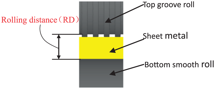
Principle of rolling groove on the surface of sheet.
In this case, both the left and right faces of the rollers and sheet are set as symmetry planes. Forming process is divided into three stages: (1) the biting stage, (2) stable rolling stage, and (3) end stage. The Z-direction load distribution during the whole process of forming is shown in Figure 2.
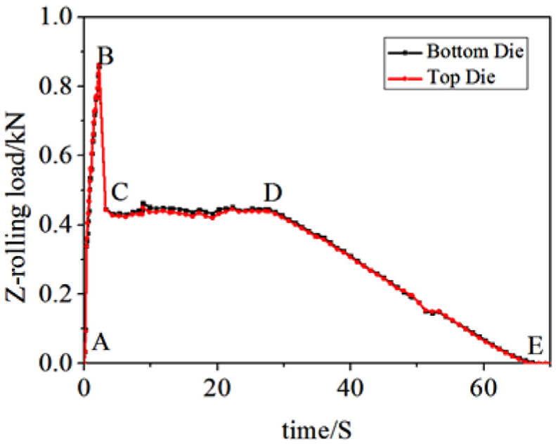
Z rolling load–time curve.
As seen from Figure 2, during the biting stage (A-B), forming load is increasing with the depth until arriving at the peak. During the stable rolling stage (C-D), forming load nearly keeps unchanged after reduction from point B to point C. During the end stage (D-E), forming load shows a downward trend.
Modeling
Materials
In this article, 6061 aluminum alloy sheet is set as the object of simulation and experimental study, and the main performance parameters are as follows: Young’s modulus is 68,947.6 MPa, Poisson’s ratio is 0.3, the thermal diffusivity is 2.20E−05 m2/s, thermal conductivity is 167 W/(m °C), thermal radiation coefficient is 0.7 J/m2, Burgers vector is 2.86E−07, shear modulus is 26,000 MPa, specific heat capacity is 900 J/(kg °C), density is 2.75E+03 kg/m3, the thermal activation energy is 376,395.8043 J/mol, and the heat transfer coefficient between the sample and the mold is 11 kW/(m2 °C). Stress–strain relationship of 6061-T6 aluminum alloy material at high temperature is shown in Figure 3.

Fitting stress–strain curves of 6061 aluminum alloy under different deformation conditions. 11
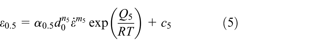
In this article, the material constitutive relations for 6061 aluminum alloy applying to heated rolling process can be obtained through following expression

Avrami model of dynamic recrystallization
Activate conditions for dynamic recrystallization is expressed by formulas as follows:
Critical strain


dynamic recrystallization kinetic equation describes the relationship between the percentage

Grain growth model
Grain size after recrystallization

In the above formula,
Simulation results
Simulation parameters in this work were described; the original length of sheet was 6 mm, the width was 2 mm, the thickness was 2 mm, and the radius of TGR and BSR were 30 mm, respectively. The profile of groove was square, and its height H was 0.25 mm, its width W was 0.5 mm and its spacing S was 0.5 mm. the profile of groove structure on the roll is shown in Figure 4. The sheet was divided into two layers, and the sheet was meshed to 100,000 elements in the top layer, and the volume of big and small elements was 1:100; TGR and BSR were meshed to 150,000 elements, respectively. According to the characteristics of the forming process, the simulation is divided into two steps. Step 1 is biting step and the sheet was nipped; Step 2 is the stable and ending stage, top and bottom rolls are rotated in opposite directions so that the sheet is moved forward along feed direction continuously, and the grooves on the roll are imprinted on the surface of sheet until the entire sheet is completed with grooves. The numerical model and simulation results are shown in Figure 5.

Schematic of groove structure on the roll.
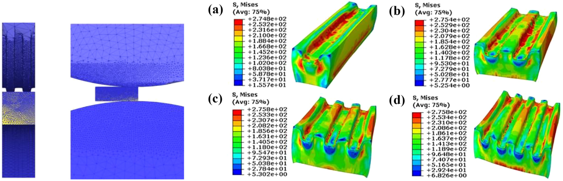
Simulation model of roll to roll to form groove and forming results based on different number of grooves: (a) single groove, (b) two grooves, (c) three grooves and (d) four grooves.
Discussion
Distribution for metal streamlines of micro-groove
Simulation and experiment results of metal fiber streamlines are shown in Figure 6. It can be seen from Figure 6(a) that the distribution of continuous metal fiber streamlines depends on micro-grooves formed. In the bottom of the groove and the bottom rounded corner, the density of metal streamline is max. Continuous metal fiber streamline is beneficial for understanding plastic deformation and change of mechanical properties procedure. The larger the local density of metal streamline, the severer the local deformation. Figure 6(b) shows the metal fiber streamlines around the micro-groove observed experimentally. The metal fiber streamlines in Figure 6(b) compare well with the simulation results shown in Figure 6(a). It can be seen from Figure 6 that severe plastic deformation is generated in rounded corner.

Metal fiber streamlines of micro-groove: (a) simulation result and (b) experimental result.
Effect of temperature on rolling
The sheets are preheated under different temperatures 330°C, 380°C, 430°C, and 480°C before rolling. Rolling rate is 0.1 mm/s, the displacement of top roll is 0.4 mm, and the difference results of rolling under different temperatures are shown in Figure 7. It can be seen from Figure 7(a) that with the increase in the forming temperature from 330°C to 480°C, the height of grooves are raised and arrived at 0.25 mm, but when the temperature exceeds 400°C, the height keeps almost unchanged. The reason is that the material is softened, material flow is increased, and flow tendency is easier in the horizontal direction than vertical direction, especially for small space such as channel on the roll, so the change of height of groove is decreased. However, it can be seen from Figure 7(b) that with the increase in the forming temperature, the grain features are changed from circular to an elongated ellipse, even some grains are fractured that is benefit for channel filled. In fact, we can see from Figure 7(c)–(f) that with the increase in the temperature, the average sizes of grain are refined.
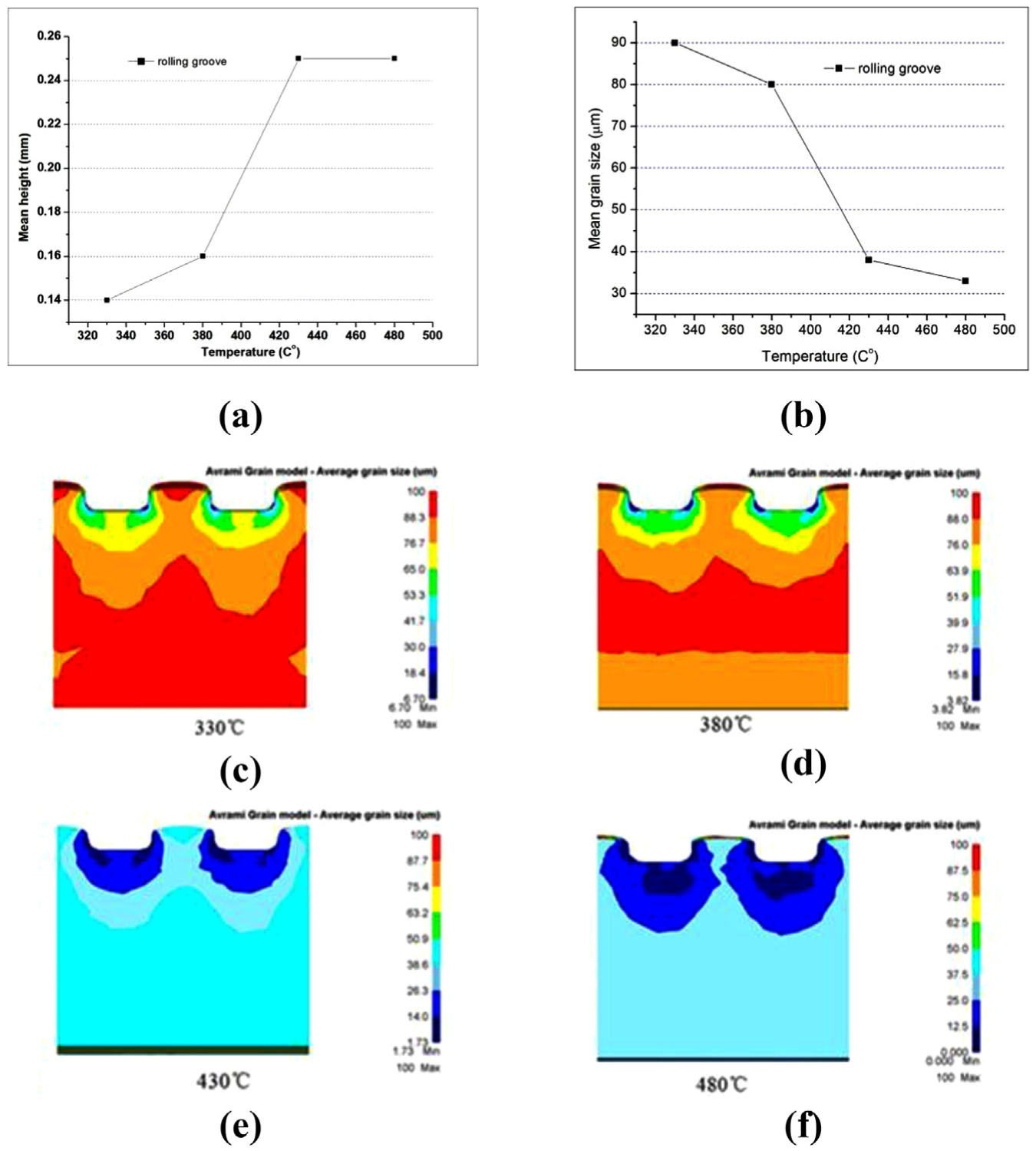
The grain size on cross section of rolling: (a) average height of groove at different temperatures, (b) average size of groove in different temperatures, (c) distribution of grain at 330°C, (d) distribution of grain at 380°C, (e) distribution of grain at 430°C and (f) distribution of grain at 480°C.
Width of channel in the roll effect on rolling
Five numerical simulations have been done in order to discuss width of channel effect on rolling grooves, during simulation, the temperature used in this process is 430°C, rolling speed rate is 0.1 mm/s, rolling depth is 0.7 mm, and the width of channel on the roll is 0.1, 0.2, 0.3, 0.4, and 0.5 mm, respectively. The changes of feature height and rolling load with different widths are shown in Figure 8.

Feature width of groove space and rolling load-groove space: (a) the change of groove’s height and (b) the change of rolling load.
It can be seen from Figure 8(a) that when the width of the groove was increased from 0.1 to 0.5 mm, there was a corresponding increase in the height of the groove and the rolling load. Figure 9 shows principle of the width’s changes of groove on the roll effect on rolling grooves. As the grain size used in the simulations are the same, the number of grains extruding into the groove are different if the groove widths used in the simulations are different. The larger the width of the groove, the more the number of grains extruded into the groove, and the easier to form the height and shape of the desired characteristics. As changes of the rolling load are shown in Figure 8(b), when the width of channel is larger, the grains in the extruding are more, because the number of grain boundaries is also larger, and the rolling load would gradually increase.

Principle of channel width effect on rolling grooves: (a) narrow channel and (b) wide channel.
Different fillets’ effect on rolling groove
Three simulations are done under the conditions of temperature being 380°C, rolling speed rate is 0.1mm/s, rolling depth is 0.7 mm, the radius of bottom fillet of channel r is 0.05 mm, the width of channel is 0.5 mm, and fillet radius of rib R is 0.05, 0.10, 0.15, 0.20, and 0.25 mm, respectively. The changes of rolling load with the change of fillet radius of rib R of simulation and experiment are shown in Figure 10. From Figure 10, it can be seen that the radius of fillet of rib changes from 0.05 to 0.25 mm, rolling load decreases gradually from 601 to 593 N, and then drops to 581 N, when the fillet radius is bigger than 0.15 mm, the rolling loads gradually increased from 590 to 605 N. However, line charts of experimental results are similar and close to simulation results. The experimental average results


Rolling load–radius of groove top fillet R.

Distribution of grain size and grain quantity on the special position P1 based on the different fillet R: (a) 0.05 mm, (b) 0.10 mm, (c) 0.15 mm, (d) 0.20 mm and (e) 0.25 mm.
Experiment of hot rolling micro-groove
The setup is developed as shown in Figure 12, and the experiments verifying the feasibility of heated rolling micro-groove on surface of sheet had been done. In the experimental process, the initial rolling temperature of the sheet is 380°C, the width of rib on the roll S is 0.5 mm, rolling speed rate is 0.5 m/s, and rolling distance (RD) is 0.1, 0.15, 0.2, and 0.25 mm, respectively, the results are shown in Figure 13, and the average height of the rib are 0.076, 0.122, 0.155, and 0.226 mm, respectively. When RD (as shown in Figure 1) is bigger, the height of rib H on the sheet is smaller because H is formed by extrusion force that is decided by RD. The radio of H/S is decreased with no change of width of rib S that is able to influence on drag reduction taking place for a rib spacing (s) to height (h) ratio between 0.2 and 0.7 with a maximum effect for h/s 0.5.22,23

Experimental equipment.

Experimental parts based on different rolling depth: (a) rolling depth is 0.1 mm, rib height is 0.076 mm, (b) rolling depth is 0.15 mm, rib height is 0.122 mm, (c) rolling depth is 0.2 mm, the average height of rib is 0.155 mm and (d) rolling depth is 0.25 mm, the average height of rib is 0.226 mm.
Conclusion
During heated rolling micro-groove on surface of sheet, grain size, geometry size, and feature size have significant effect on rolling. In this article, numerical models of heated rolling micro channel on surface of sheet are computed, and correlation analysis is discussed. And also, the experiments verified the feasibility of the method. The conclusions are as follows:
Heated rolling micro-groove has continuous metal fiber streamlines; compared with machining method, it has better mechanical properties.
When grain size is fine, number of grains extruded into the gap is large, so it is easier to form the desired height. But when the grain is fine, the grain boundary is more, so the deformation resistance and the rolling load increase.
Increasing the groove width correspondingly increases the number of grains extruded into the gap, thereby making it easier to form the height and shape with desired characteristics. But the number of grain boundaries is also larger, and because the grain boundaries hinder the forming process, the flow stress of deformation is higher.
By increasing the top fillet radius, it becomes easier to roll the micro-grooves to desired height and shape.
Footnotes
Handling Editor: Kang Cheung Chan
Declaration of conflicting interests
The author(s) declared no potential conflicts of interest with respect to the research, authorship, and/or publication of this article.
Funding
The author(s) disclosed receipt of the following financial support for the research, authorship, and/or publication of this article: The authors would like to express their gratitude to the support from NSFC (grant nos 51275201 and 51311130129), Key Project of Science and Technology Department of Jilin Province (grant no. 20140204062GX), and Royal Society (grant no. IE121495).