
Abstract
Compared with automatic collision avoidance systems, collision avoidance assistance systems have attracted more research interest because they help avoid collisions in near-accident situations. However, ensuring the robustness and reliability of collision avoidance assistances is difficult because of problems in reliable environment recognition, accurate collision avoidance decision making, and driver acceptance. This article reviews and analyzes three essential technologies for collision avoidance assistance systems in intelligent environment-friendly vehicles. The architecture of the human-in-loop system is summarized, and available environment recognition methods used in collision avoidance assistances are compared. Moreover, the characteristics of path planning and collision avoidance decision making applied in emergency collision avoidance assistance systems are reviewed, and the advantages of applying haptic share control and yaw moment active intervention during path tracking are analyzed. The emergency collision avoidance assistance systems based on driver behavior models and HSC were found to be the most suitable for high-speed emergency conditions. Such systems are not only highly robust but also more likely to be accepted by drivers.
Keywords
Introduction
Depending on the time of deployment, collision-related safety systems can be classified as passive and active safety systems. Conventional seatbelt and airbag systems, installed to reduce injuries to the driver and passenger after a collision, and rescue systems, such as those that automatically notify rescue centers of the location of an accident,1,2 are examples of passive safety system. With the increasing adoption of camera and radar sensing technologies in current automatic driving systems and driver assistance systems, collision avoidance (CA) systems have extensively focused on the domain of precrash,3,4 which can warn or assist the driver, and even control the vehicle automatically in dangerous situations; such systems are active safety systems.
CA systems are crucial in automatic driving systems; although automatic CA systems have been developed, they cannot accurately manage complex traffic environments because of limitations in sensing technologies, thus reducing their reliability. In addition, automatic driving technologies are yet to mature, and much progress must be made before they can be industrialized. Therefore, applications of automatic CA systems have been limited.
Collision avoidance assistance (CAA) systems help avoid obstacles at emergency high-speed situations by employing the conventional driver-in-loop driving systems; it is an important part of active safety systems. In CAA systems, the driver retains the highest control level of the vehicle and can override the system, thus effectively preventing false system triggers and improving system safety and reliability. CAA systems such as collision warning (CW), lane departure warning (LDW), lane keeping assist (LKA), and automatic emergency brake (AEB) systems are currently mass produced. 5 The CW and LDW systems warn the driver when potential collision danger occurs but do not take any measures for avoiding collisions or controlling the vehicle. The LKA system works when the system detects that the vehicle is about to deviate from a traffic lane due to the driver lack of concentration or fatigue driving and applies a small amount of counter-steering force. The AEB system applies the braking automatically in response to the detection of a likely collision and avoids the longitudinal potential collision. However, during emergency CA situations, the driver may steer rather than brake, particularly during sudden situations, where steering may precede or be accompanied by braking. Therefore, CAA systems that include steering intervention have gained research attention. 6 Project PRORETA, a collaborative project between automotive supplier Continental and Technische Universität Darmstadt, introduced steering intervention for CAA systems. Furthermore, Eskandarian et al. 7 reported the classification and architecture of the system but only for conventional vehicles.
One of the current transformative developments in the automotive industry is the intelligent environment-friendly vehicle (i-EFV). On the basis of the human–vehicle–road (HVR) interaction, i-EFVs realize assisted driving with multiple objectives, 8 such as traffic safety, energy optimization, and environmental protection. Emergency CAA systems in i-EFVs use such technologies as radar sensing and cameras in advance driver assistance system (ADAS) or network communications among vehicles to obtain information, such as the presence of obstacles, from the road environment. On detecting a collision risk, the controller determines the target path and compares it with the actual vehicle path. After identifying driver intention and behavior, the controller evaluates the adequacy of the driver’s braking and steering. Subsequently, actuators (e.g. active front steering (AFS), electronic power steering (EPS), four-wheel steering (4WS), additional yaw moment control (YMC), and electronic stability control (ESC) that execute appropriate braking 9 or steering6,10 interventions to avoid a collision are triggered. These actuators work cooperatively with the driver through a human–machine interface to avoid collisions.
The emergency CAA systems in i-EFVs differ from automatic CA systems. After collision risk assessment, the active intervention in i-EFV CAA systems depends on driver behavior because driver-in-loop characteristics are considered in the intervention. Furthermore, the unique power train and chassis control systems in i-EFVs introduce new problems in CAA. Therefore, the essential technology research of CAA system in i-EFV has its particularity and significance.
This article focuses on emergency CAA systems in i-EFVs. The second section gives the system architecture and the advantages of the three essential related technologies: environmental perception and driving behavior recognition, CA decision making and path planning, path tracking, and human–machine shared control. The third section analyzes the characteristics of environmental perception methods and the driver behavior model used in emergency CAA systems. The fourth section reviews the types of CA strategy and the methods of path planning. The fifth section points out the advantages of haptic share control (HSC) and the active intervention of the stability systems in path tracking. Finally, a conclusion and the future of research on emergency CAA systems are discussed.
System descriptions
System architecture of CAAs in i-EFVs
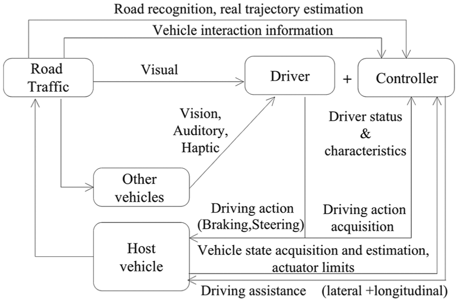
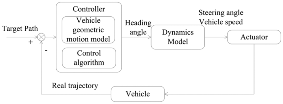
The HVR interaction is illustrated in Figure 1(a). The driver initiates the driving action after visually perceiving the road environment. The vehicle trajectory calculated on the basis of the driving behavior is feedback to the driver, thus creating a closed loop. Hayash 11 proposed an HVR-based automatic CA system in which the target path is planned on detecting an obstacle through light detection and ranging (LiDAR). Subsequently, the vehicle dynamics model generates the desired driving action, using which the controller corrects the vehicle path according to the deviation between real and target trajectory (Figure 1(b)). This method does not identify or predict driver behavior (i.e. it does not use the driver-in-loop approach) and thus has limitations when applied in the emergency CAA systems in i-EFVs.

(a) HVR system and (b) automatic CA control system.
Conventional HVR-based i-EFVs consider the relative movement among vehicles to generate restrictions for the host vehicle and the other vehicles on the road. In addition, they use driver-in-loop systems to strengthen the driver’s control over the vehicle, thus accomplishing human–machine shared control. Figure 2 depicts the system architecture of an i-EFV emergency CAA system. After obtaining data on the road environment, the motion of the host and other vehicles, and the driving action, the controller generates assistive driving actions to control the vehicle cooperatively with the driver.
System structure of an i-EFV emergency CAA system.
The i-EFV emergency CAA system is advantageous over the conventional HVR automatic CA system for the following reasons:
Compared with the driver preview model (road information → driver preview model → driving maneuver → vehicle motion) used in the HVR CA system, the real-time driving behavior–based model used in the i-EFV CAA system can judge driver intention more accurately, leading to faster closing of the human–machine loop.
The i-EFV CAA system has fewer false triggers because of the inclusion of the driver-in-loop system, through which the driver can override system actions.
Driving conditions can be predicted using the driver behavior model established within the controller, and multiple objectives can be accordingly optimized. For example, during emergency conditions, safety can be prioritized as the primary optimization goal, whereas during normal driving conditions, comfort, energy conservation, and environmental protection can be targeted.
System analysis of emergency CAAs in i-EFVs
The essential technologies in emergency CAA systems in i-EFVs can be classified into three:12,13 environmental perception and driving behavior recognition, CA decision making and path planning, and path tracking and human–machine shared control (Figure 3):
Environment and driving behavior recognition. Using such technologies as LiDAR and millimeter-wave radar sensing as well as cameras and vehicle–vehicle communication, data on the road environment, such as the presence of pedestrians, vehicles, and obstacles, are obtained. Data on the vehicle status are acquired by monitoring wheel speed, through global positioning system (GPS), and using sensors such as accelerometers. The integration of these data with vehicle dynamics improves environmental perception and accuracy of the vehicle position and status estimation. In contrast to automatic CA systems, emergency CAA systems monitor driver inputs such as steering wheel angle and torque, gas pedal travel; that is, the driver behavior model is used to effectively identify the driving conditions and driver intentions.
CA decision making and path planning. The emergency CAA system controller evaluates the collision risk on the basis of the identified traffic, road, and vehicle status. In addition, the controller identifies and predicts driver intention using driver input. After analyzing these two sets of data, the controller determines and executes the appropriate avoidance action by planning the target path under actuator constraints, thus ensuring vehicle stability.
Path tracking and human–machine shared control. After determining the appropriate CA strategy, the generated braking and steering system intervention in path tracking must meet tracking accuracy and vehicle stability requirements. The human–machine shared control strategy generates driving-assist action to compensate for the deviation between the driver input and the planned ideal input. During path tracking, the coordinator ensures that the multiple actuators 14 work toward the same objectives and that they do not conflict, thus realizing rapid and effective CAA action.

Essential technologies in i-EFV CAA systems.
Environment perception and driver intention recognition
Environment perception
The i-EFV environment comprises several components, such as pedestrians, road conditions, traffic conditions, weather, and vehicle status. Accurate assessment of these components is a precondition for safe CAA driving. These components in turn entail involve variables, such as curvature, road slope and adhesion, and amount of fog, rain, and snow. Thus, the CAA system must be equipped with various sensors, such as camera-based video image processors, radar sensors, vehicle-to-X (V2X) sensors, digital maps, and vehicle status sensors.
Video image perception and processing technology
Examples of video image processing applications in vehicles include lane recognition and obstacle (e.g. pedestrians 15 and vehicles) recognition.
Lane recognition. Lane recognition processes (Figure 4) can be classified as processes based on characteristics 16 (e.g. color 17 and texture 18 ) and those based on road curve parameters (e.g. straight lines,19,20 splines, linear parabolic curves, hyperbolic curves, 21 and B Snake 22 ). The vehicle environment varies widely because of differences in such factors as weather, sunlight, and shadows. Therefore, characteristics-based approaches cannot effectively recognize lanes; moreover, such approaches entail large calculations and thus have poor real-time performance. In comparison, road curve parameter–based lane recognition approaches have better real-time performance.
Obstacle detection and recognition. Obstacle detection methods can be classed as motion-based and shape-based.
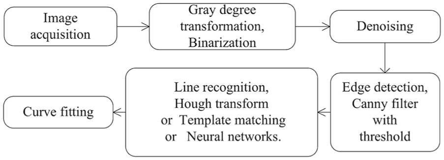
Lane recognition process.
Motion-based methods recognize obstacles by analyzing the motion characteristics of the identified targets. 23 Thus, this approach is independent of variations in factors such as color, texture, and light. However, only moving targets can be detected; furthermore, this method entails comparison of multiple image frames, which affects real-time performance.
In shape-based methods, features of the targets are extracted and compared with models of the human body and vehicle geometries. The histogram of gradient method is used for pedestrian feature extraction. Yasuno et al. 24 established a two-dimensional (2D) model of the human body, and Broggi et al. 25 established a three-dimensional (3D) infrared image–based model of the human body. Gavrila and Munder 26 proposed an outline-based hierarchical matching algorithm based on outline. Lu et al. 27 combined pedestrian, vehicle, and lane detection and set the triangular region formed by two lane dividers as the range of interest. Subsequently, the width:height ratio and dispersion characteristics of obstacles in this area were extracted, following which the obstacle type was determined through feature fusion.
By contrast, shape-based obstacle detection methods are superior motion-based methods because complex characteristics of human and vehicle movement are analyzed in the former; moreover, shape-based methods can detect static obstacles.
Radar perception technology
Radars in vehicles can be classified as ultrasonic, millimeter wave, 28 and LiDAR29,30 according to their working principle. Ultrasonic radars are simple and inexpensive but are influenced by weather, and the sensing distance is limited to 4–5 m. Hence, they are generally used in reversing and parking alarm systems. Millimeter-wave radars can be classified as 24-GHz mid-distance and 77-GHz long-distance radars. 31 They are not influenced by weather; hence, they are widely used in adaptive cruise control and other ADAS systems. LiDAR has many favorable characteristics, such as a detection range of up to 100 m, high speed, high stability, and 3D imaging, but it is expensive and easily influenced by the environment. Millimeter-wave radars,28–30 by contrast, is relatively less expensive, is not easily influenced by environmental elements, and has precision; thus, they are suitable for use in CAA systems. 32 Radar cross-section, multi-target recognition, wave studies, signal processing, and transceiver isolation are essential technologies in millimeter-wave radar sensing. The electromagnetic compatibility and space electromagnetic interference of radars and other hardware systems33,34 must be reviewed. Because radars use radio frequencies, they are not further considered in this article.
V2X technology
V2X technologies are technologies used in information exchange between a vehicle and its environment, such as vehicle–road communication and vehicle–vehicle communication.35,36
Vehicle–road communication, such as vehicle–base station communication and GPS navigation, 37 requires the deployment of roadside communication devices, for example, detectors and wireless transmitters. The transmitter sends the data on accidents, weather, and road curvature and adhesion coefficients 38 obtained by the detectors to vehicles in their range.39,40
The dedicated short-range communication (DSRC) technology is used in vehicle–vehicle communication for transmitting information such as safe distances and warnings to the rear vehicle. DSRC is a highly efficient wireless communication technology developed especially for traffic management; through DSRC, voice and non voice data can be transmitted in real time. Ad hoc 41 proposed a multi-hop networking wireless mode in which each vehicle in a local area network is a communication node; all nodes adjust their behavior according to the defined protocol.
Sensor perception and information fusion technology
Vehicle dynamics sensors, such as wheel speed sensor, steering wheel angle and torque sensor, and yaw-rate sensor, are used to obtain information on the vehicle status. A single sensing source cannot yield reliably information; therefore, sensor fusion technology must be used.42,43
Regarding the integration of video and radar technologies, Polychronopoulos 44 and Guo et al. 45 proposed the fusion of millimeter-wave radar and video image processing: first, a region of interest is established on the camera image on the basis of the distance information obtained using the vehicle geometry model and the millimeter-wave radar. Subsequently, the AdaBoost algorithm detects vehicles. Later, Aharon et al. 46 proposed a secondary fusion technology using vehicle dynamics, yaw-rate sensors, GPS, and digital maps (Figure 5). Useful information extracted from the image is transferred to the vehicle through transformation and camera calibration. Furthermore, to improve the reliability and robustness of this system, Zhang 47 proposed a steady state prediction hypothesis, combined signals from radar, predicted lateral and longitudinal vehicle movement, and presented a forward collision warning algorithm suitable for high-speed driving on curved roads.
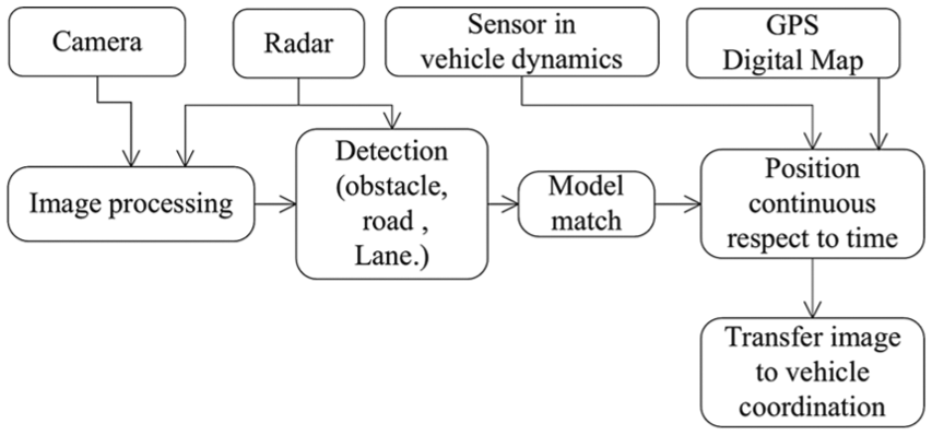
Sensor fusion.
Through the information fusion, the disadvantage of single source has been compensated, and the accuracy of the perception could be improved. i-EFVs are equipped with emergency steering CAA functionalities; therefore, fusing vehicle dynamics sensors and vehicle–vehicle information sensors and integrating vehicle kinematics and dynamics models can improve the accuracy of vehicle–vehicle and vehicle dynamics parameter estimation. But, as the data processing of the fusion takes time and requires hardware with higher performance, it increases the complex and cost of the system development. As the vehicle state sensor is already existed, the fusions of these sensors are suggested to be considered first.
One of the new problems for sensor fusion is the location of doing the data processing, a central fusion electronic control unit (ECU) or the local sensor module. The former one reduces the design of sensor, but the broadband communication has to be used as the huge amount of information. The latter one enables using low-cost communication interface but increases the complexity of local sensor. Therefore, a compromised design should be better, that is, only integrate the data processing in sensors require large amount of information, such as millimeter-wave radar, LiDAR, and camera. And the information sends directly for other low information sensors.
Driver behavior model
Driver behavior refers to the actions that a driver executes in response to the behavior of the environment and other vehicles. Through the driver behavior reverse model, the acquired driver input is used to deduce the driver and environment characteristics and to predict subsequent behavior (Figure 6). Driver behavior models can be classified into two: 48 description models and function models. Description models focus on identifying driver behavior; their prediction ability is limited because they do not consider differences in the behavioral characteristics of different drivers. Function models focus on analyzing the cause underlying driver behavior and can thus differentiate between actual and desired driver behaviors. Examples of function models include driver intention identification and risk assessment. Function models are more suitable for emergency CAA systems in i-EFVs.

Scope of driving behavior.
Function models comprise information processing models and motivation models. Information processing modeling is based on the human mindset and has three components: perception, decision making, and actuation. The three components are implemented sequentially or are interlaced with each other. Information processing modeling embodies the ability of the human mindset well and can predict the future behavior of a driver through data analysis; however, changes in the driver characteristics such as mood and fatigue are not considered. Motivation models consider interactions among the driver, vehicle, and environment. Depending on the situation, the driver is treated as an active decision maker and memory searcher, and driver characteristics, such as age, physiological and mental states, and driving habits, 49 are reflected in risk assessment and compensation.
Vehicle behavior can be abnormal when the vehicle is controlled by both the controller and the driver. Thus, motivation models should be used in i-EFV emergency CAA systems to analyze driver behavior. Liu 50 established a method for evaluating a driver’s physiological and mental states and developed a safe distance model through an experimental weighted-data method. This rationality of the weighted factors was subsequently verified through simulations. Chen 51 used the ratio of the ideal braking deceleration and the maximum braking ability of the vehicle as a safety factor for determining avoidance action. Zhang 47 established a forward collision warning algorithm for curved highways and tested it by simulating various CWs. Luo 52 used a fuzzy decision system to analyze drivers’ historical data in order to determine the lateral speed and position for classifying driving styles through Mamdani inference. Liu 30 combined a mathematical model and a back propagation (BP) neural network; in this model, the initial velocities of the host and forward vehicles are the inputs to the neural network, and relative deceleration and stopping distance are the outputs. The weights of the network and the thresholds can be adjusted online to customize the safe distance model to the actual scenario.
CAA strategy and path planning
When a CAA system in i-EFV detects an emergency situation, the controller evaluates the risk of collision and plans a practicable ideal CA path. The CAA strategy refers to the method of intervening and sharing feedback with the driver53–55 to accomplish CA through human–machine shared control.
CAA strategy
Most CAA strategies are based on collision time 27 and collision distance56,57 but have different intervention methods and thresholds. For example, collision time–based strategies may provide safety warnings, braking assistance, automated braking, steering assistance, or automated steering. 3 In Figure 7, the horizontal hollow arrows represents the time to collision (TTC), and the vehicle is initially in the normal driving mode and is safe. On identifying an obstacle and validating the collision risk, 58 the controller reminds the driver to take action through auditory and visual warnings. This stage is termed the CW stage, and the trigger threshold is called time to warning (TTW). If the driver is late in braking, the CAA system activates brake assistance and amplifies the brake effect according to driver intention and the lane environment. This stage is called the time to support brake (TTSB). If the driver does not take action, the controller determines the necessity for automatic braking and executes braking, if necessary. This system is called the AEB, and the corresponding trigger threshold is termed the time to brake (TTB). Subsequently, if the system determines that the applied braking alone is inadequate, steering assistance—either assisted steering or automatic steering—is triggered. In assisted steering, the controller is triggered if the driver’s steering action deviates from the generated ideal path. The corresponding trigger thresholds is called time to support steering (TTSS); similarly, the corresponding trigger in automatic steering is called time to automatic steering (TTAS).

Stages of CAA strategy.
Higher TTAS thresholds lead to smooth steering, but the intervention is triggered early, which may startle the driver and thus reduce driver acceptance of the system. By contrast, lower TTAS thresholds lead to sharp steering, and the large accompanying lateral acceleration may reduce vehicle stability, possibly leading to driver panic and consequently, false steering action. Hence, TTAS thresholds should be moderate, and both the maximum steering angle, under constraints of the steering mechanism, and the maximum steering wheel rotation speed input from the driver should be considered.
Path planning
In path planning, the optimal CA path is determined according to the state of the vehicle and the external environment. 59 Compared with automatic driving, emergency CAA systems in i-EFVs require more intense path planning because of the following reasons: (1) emergency CAA systems function in dangerous situations, for example, at high vehicle velocities and with sudden obstacles, meaning that the driver has less time to react. (2) The driver is part of the emergency CAA system operation. (3) CA path planning should maintain vehicle stability.
Emergency CA path planning strategies are summarized herein:
Path planning based on potential field. CA path can be determined using a series of elastic bands on the basis of the obstacle direction and speed. 60 Xiao 61 proposed an active CA method that is based on a repulsive field and established an abacus path model in which the vehicle is treated as counting beads. The counting beads are balanced between the road borders’ repulsive force, the obstacle force, and the spring force among the counting beads. The resulting balanced path is the CA path. Such field methods are characterized by its simple structure, high real-time performance, and easy programmability.
Path planning based on model and established rules. Model-based path planning includes straight lines, arcs, exponential curves, and S curves and is often used to avoid collisions in situations when only a single obstacle is present in front of the host vehicle. This approach may not yield the optimal CA path, but it can generate a suboptimal method to ease the collision when collision is unavoidable. Wang 62 used a multi-sensor self-adaptive threshold method for local path planning. You 63 used polynomial track algorithm for path planning and lane change and validated the practicability of this method through virtual reality modeling language/Simulink simulation. Ren et al. 64 determined the target acceleration for path planning using the time to lane crossing (TLC) model.
Path planning based on optimal control. In optimal control–based path planning, parameters such as minimum path time, minimum path distance, minimum geometric motion, maximum comfort, minimum energy consumption, and maximum safety are optimized. Optimal control thus accounts for multiple objectives but at the expense of real-time performance, especially when vehicle motion is nonlinear. Examples of widely used CA path planning algorithms include particle swarm optimization, ant colony algorithm, 65 convolution algorithm, and secret mother algorithm. However, vehicles cannot be considered as particles because CA systems must account for vehicle size and other physical constraints such as turning radius and velocity change ratio. To increase the practicability of path planning, Ross and Fahroo 66 and Peters et al. 67 have realized smoother and continuous curvature path planning using the differential flat theory.
Path tracking
The objective of path tracking control is to ensure that the vehicle follows the preplanned CA path from any initial position through lateral steering control and longitudinal acceleration or deceleration control.
Haptic human–machine shared control
CAA systems in i-EFVs use the driver-in-loop human–machine shared control (Figure 2). Human–machine shared control is of two types: input mix control and HSC. 68 Input mix control varies the inputs to achieve the control objectives by analyzing the relationship among multiple inputs or the system responses produced by the different inputs. HSC changes the physical parameters of a human–machine interface and employs bidirectional communication. The HSC output directly affects the vehicle.
In CAA steering, when steering wheel angle is the selected control variable, the angle cannot be directly fedback to the driver because it must be obtained by path tracking error estimated by the driver. Therefore, this type of human–machine shared control is of the input mix control type: it fuses the steering wheel angle input from the driver and the machine and accordingly adjusts the system output to complete path tracking through feedforward and feedback. 69 When steering torque is the control variable, the shared control is of the HSC type because torque is a physical quantity that is perceived directly by the driver. The torque sensor installed on the vehicle steering column can measure driver input to realize human–machine shared control.
Therefore, for CA path tracking, emergency CAA systems in i-EFVs use the inverse driver behavior model to obtain the ideal driver input on the basis of the path tracking error. When the real driver input deviates from the ideal driver input, the controller generates assisting steering force to realize human–machine shared control. The driver input was analyzed by Mashadi and colleagues,70,71 and a driver model–based controller was designed for path tracking, the controller considered the YMC in lateral dynamics as well.
Abbink and colleagues have done substantial research on experimental verification of HSC.68,72–77 They described the advantages of HSC, especially during CA, as follows: drivers can perceive the magnitude of the force of the automatic intervention at all times and can actively suspend the CAA system at any time. By contrast, when using the input mix control method, drivers cannot override the CAA system and may not even be aware that the system was triggered. 68 Petermeijer 74 classifies CAA systems as guiding systems that assist drivers in safe driving and in following the preplanned path to avoid collision. The fundamental problem in human–machine shared control is to determine the relationship between machine feedback and driver response under a particular driver input (e.g. selection of the machine system feedback mode, driver intention recognition, activation and deactivation of the CAA system, 78 and degree of driver acceptance).
Corno 79 applied HSC to drive-slip control and used an HSC controller to adjust the gas pedal force to prevent wheel slip, which is different from conventional traction control system (TCS). Similarly, Makoto et al. 80 applied HSC to pedestrian CA to exert a force on the steering wheel to assist the driver in turning to the ideal steering angle to avoid collision. Katzourakis et al.75,81 investigated human–machine shared control under limit conditions and verified the assistance effect generated by HSC through vehicle tests.
Path tracking control strategy
Path tracking control strategies can be classified as follows depending on the control objective and employed algorithm:
1. Path tracking control based on vehicle model. Decoupling the multivariate vehicle kinematics model makes the number of control variables equal to the degrees of freedom of vehicle model, then local linearization of the vehicle kinematics.82,83 Steering wheel angle and velocity are usually selected as the control variables. After decoupling, the path tracking method is simple and involves simple calculations; however, the tracking accuracy is decreased when the vehicle is in sideslip condition because of model inaccuracy.
To compensate for the problems induced by decoupling and linearization, Ma 84 designed transfer function K1 and K2 using fuzzy control to increase lateral and longitudinal linkage (Figure 8). Hima et al. 85 used a proportional–integral–derivative controller to control the longitudinal motion and used adaptive control method to control the lateral motion after decoupling the dynamics model to overcome the drawbacks of parameter uncertainty in the vehicle model. Valerio et al. 86 and Frasch et al. 87 adopted predictive control88,89 to predict longitudinal path and to build the lateral vehicle dynamics model on the basis of the hypothesis that vehicle model can be linearized under large curvature of road. Under the constraints of actuator capability and vehicle stability, model predictive control was used to find the optimal control parameter through rolling optimization during each period. The test results show that this method can avoid multiple obstacles and that it is applicable in wet slipped roads. To eliminate system interference, Ruan et al. 69 used the active disturbance rejection control method to establish a decoupled controller for tracking the longitudinal velocity, the lateral displacement, and the yaw rate. The rule of tire force allocation was designed through nonlinear programming and the Burckhardt nonlinear tire model. The results of typical double lane change path tracking simulation validated the effectiveness of this method.

Vehicle model–based path tracking.
Path tracking control based on trajectory error (Figure 9) can avoid these problems;90,91 however, this method requires high-precious GPS to acquire a vehicle’s current location, which increases system cost. To reduce cost, sensors currently commonly installed in vehicles, such as wheel speed sensor, acceleration sensor, yaw-rate sensor, and low-cost GPS, can be used to approximate vehicle location. Summet et al. 91 combined on-board diagnostics velocity signal and 0.02-Hz low-frequency low-cost GPS data (e.g. from low-cost mobile phones and navigation equipment) using extended Kalman filter to estimate the vehicle motion path and tested the algorithm in real vehicles. Taek and Chung 92 combined GPS and a low-cost inertial measurement unit using Kalman filter to obtain precise location information. Because of the model error in changing head angle into steering wheel angle and the lack of consideration of tire nonlinear and centroid position change during steering, tracking accuracy and safety can be improved by considering vehicle dynamics models and by integrating parameters such as sideslip angle93,94 and yaw rate in the model to form feedback control.95,96
Trajectory error–based path tracking.
2. Path tracking control based on preview model.15,20,97 The planned path is transferred into the target heading angle through the driver preview model, as shown in Figure 10.
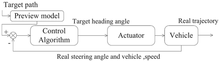
Preview model–based path tracking.
In the preview model, the driver can view the simulated travel path in advance. The preview models calculate the target control variable according to the road curvature. Therefore, preview models most closely reflect a driver’s control characteristics. Driver preview models are of three types:
Transfer function preview model. Design forward correction or feedback assessment transfer function is used to simulate driver perception and to predict driver behavior. 98 The accuracy of this model depends on the experience parameters used in transfer function; ensuring the accuracy and effectiveness of this model in all conditions is difficult.
Optimal preview model. Chen and Guo 99 presented the preview optimal curvature model in 1984 in which the optimal curvature was transformed as the optimal steering wheel angle according to the Ackerman geography relationship. Furthermore, Sharp et al. 100 introduced preview path error and Salvucci and Gray 101 simplified the error model; both these optimized models reduce or eliminate errors. Markkulaab et al. 102 analyzed and compared the performance and effectiveness of the aforementioned optimal preview models through simulations.
Preview models are based on algorithms such as fuzzy control and neural networks.80,103–106 Using complex network topologies, preview models consider actual driver behaviors as training samples. However, given the paucity of training samples, such methods are rare. To solve this problem, Xiao 61 used feedback to correct the path through optimal lateral acceleration. Wu 107 used two neural networks to identify vehicle velocity and steering wheel angle and experimentally identified the relationship between the inputs and outputs.
Stability control in path tracking
When using emergency CAA systems, inexperienced drivers tend to oversteer. When the ground cannot provide the required lateral force, the vehicle skids and loses stability. Therefore, path tracking stability must be considered in CA.108–110
Emergency CAA systems in i-EFVs differ from conventional ESC as follows. ESC control systems are based on state of the vehicle, that is, the system is triggered when the vehicle oversteers or understeers. Emergency CAA systems are triggered when the tracking error is higher than the threshold and thus relies not only on the driver input but also on the vehicle environment. In addition, the inputs to these two systems are different: ESC systems use steering wheel angle as the input, whereas emergency CAA systems use the driver’s steering behavior and vehicle’s tracking error as the inputs. Moreover, the control objectives of the two systems are different: ESC systems ensure vehicle stability, whereas CAA systems monitor trajectory error as the control objective under the constraints of vehicle stability.
According to the vehicle dynamics model, stability can be ensured during path tracking by calculating instability boundaries for steering angle and velocity. However, this approach compromises the tracking capabilities. Zhao 105 proposed an algorithm to calculate steering angle and velocity under safety constraints using tire–road adhesion, sideslip angle, and yaw rate. The algorithm was validated through simulations on a rectangular track at 60 km/h. Huang 20 adopted a double-loop control structure to achieve trajectory tracking (Figure 11). The outer loop uses integral inversion to design the trajectory tracking controller. The inner loop use the PI+ sliding mode method to design the dynamic controller and yields steering wheel angle and the longitudinal distribution of tire force as outputs; simulation results confirmed that the control algorithm can achieve stable lane changing on curved highways. For path tracking on curved roads, Ren et al. 64 transformed the vehicle lane changing trajectory into the yaw rate trajectory and proposed a stable path tracking method based on yaw rate closed-loop control; the effectiveness of the algorithm under different curvatures were verified through simulations.
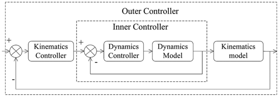
Double loop CA control structure.
After detecting stability loss during path tracking, additional YMC can be generated from systems such as ESC, differential braking systems, and 4WS to improve vehicle stability.111,112 Joa et al. 110 introduced the lateral driver model for accurate path tracking even at large sideslip angles (Figure 12). The main controller comprises upper and lower controllers; the upper controller calculates the expected lateral tire force according to the path and the vehicle information, and the lower controller transforms the front wheel tire force to steering wheel angle. Feedforward and feedback control are adopted in both controllers. Upper feedback control is used to minimize lateral displacement, sideslip angle, and yaw rate error and to realize stable path tracking. Lower feedforward control calculates the steering angle using vehicle kinematics and the two-degree-of-freedom dynamic model to minimize modeling error. Furthermore, Eunhyek et al. designed a proportional–integral feedback controller on the basis of the minor tire lateral force error. MATLAB/Simulink and CarSim co-simulation of the lateral driver model on an S-shaped road evidenced the high performance and realism of the model.

Upper and lower control structure for stable path tracking.
Choi et al. 113 classified target yaw rate for stability control and desired for CA trajectory tracking error using the index of collision as the overlaying weights overlaying, and the ESC system is used for target yaw rate tracking. This algorithm reduced the TTC compared with non active YMC intervention. In addition to YMC control, coordinating the steering system yielded a more effective and stable CA performance. Through YMC support, Choi et al. 114 compensated for the delay in driver response by overlaying steering torque and increased the minimum safe distance before the CA system is triggered. To improve driver acceptance, 115 Lee and Yi 116 used steering torque rather than steering angle as the output variable; in their model, the generated assist torque was proportional to the angular deviation between the actual and target steering angles. Moreover, CarSim/Simulink simulations demonstrated that this robust predictive control method substantially improves vehicle safety and driving quality.
The human–machine shared control and YMC system active intervention satisfy the requirements of emergency CAA systems in i-EFVs (e.g. safety, environmental protection, and comfort). Such shared control can improve system robustness, safety, and stability and can conserve energy using motor-assisted braking.
Conclusion
The architecture of the emergency CAA systems in i-EFVs has been presented, and three essential technologies have been discussed. First, the methods of environment recognition has been reviewed and analyzed, such as video, radar, V2X technologies and its integration, and the driver behavior model has been introduced as well. Second, the strategy and path planning have been reviewed. Third, path tracking and HSC were discussed. Emergency CAA systems are essential for advancing automatic driving technologies, functioning at high-speed CA conditions, and assisting drivers in steering along the planned target path. The integrating of driver input in the CAA system improves driver acceptance of the system.
Emergency CAA systems in i-EFVs integrate data on the road environment into a HVR system. By fusing data from multiple sources (e.g. cameras, radars, and environment recognition devices), the reliability and accuracy of environmental perception can be improved. The performance of the fusion not only depends on the fusion technology but also relates to the combination method. The implementation of sensor fusion should consider the higher system complex and cost as well.
In order to improve the acceptance of the CAA system, the robustness of the CA strategy in i-EFV emergency CAA systems can be enhanced through accurate identification of driver intention and abnormal driving situations. Thus, a realistic driving behavior model, including those for abnormal behavior detection, should be focused on in the phase of path planning and path tracking, and conventional offline data analysis–based behavior models should consider uncertain parameters in the HVR system and must adapt online identification for corrective interventions.
Human–machine shared control is essential in emergency CAA systems for safety path tracking and higher system request. In the emergency CAA system, the steering torque–based HSC shows better performance when compared to the conventional driver preview models, and it considers the characteristics of different drivers, reduces the false trigger, and improves the feeling of driver’s control right. The HSC and vehicle dynamics–based active intervention are other emerging research fields pertaining to emergency CAA systems in i-EFVs.
During emergency CAA path tracking, on the basis of higher tracking accuracy, the stability of the vehicle needs to be guaranteed. And the active intervention of the vehicle dynamic systems further improves the CA capability of the vehicles. The YMC-based motion control coordinated with the electronic steering system is likely to increase driver acceptance and meanwhile keeps the vehicle stability.
There are two points that have not been described in detail and will be studied in the future: first, as the TTC-based CA strategy is sensitive to time, so the accuracy of the TTC estimation is crucial, and the driver acceptance need to be analyzed in threshold setting. Second, there are multiple power sources existing in electric or hybrid vehicles could support CA system, and the study of the optimized combination is valuable.
Footnotes
Academic Editor: Anand Thite
Declaration of conflicting interests
The author(s) declared no potential conflicts of interest with respect to the research, authorship, and/or publication of this article.
Funding
The author(s) disclosed receipt of the following financial support for the research, authorship, and/or publication of this article: Grant U1564208, National Natural Science Foundation of China.