
Abstract
In this article, the reliability assessment and management of low-voltage switchgear was introduced based on a hierarchical Markov model. First, the reliability block diagram of motor control center was established by actual circuit. The low-voltage switchgear was divided into modules by different functions of reliability block diagram to build the hierarchical structure model which contained five layers. The first and the second layers were low-voltage switchgears and modules, helpful to identify key modules. The others were units and components, essential to establish the reduced model. Therefore, the state transition diagrams of layers were plotted and the transition density matrixes of layers were given easily. Steady-state equations of each layer were constructed and solved to obtain the availability and steady-state probabilities of modules and components. Next, the reliability assessment and management of GCK4 low-voltage drawer-type switch cabinet motor control center was presented. Finally, critical components and critical modules were found, but their running state in the management process should be carefully monitored. The hierarchical Markov model realizes a rapid and convenient analysis of system reliability. The results provide theoretical support for identifying key module and component and developing rational maintenance and management strategy for low-voltage switchgear and other repairable complex systems.
Introduction
Low-voltage switchgear, an essential device in industry automatic production, is responsible for the completion of the control, protection, measurement, conversion, and distribution of power in process of industry automatic production.1,2 The operational state of the equipment directly affects the security and stability of the whole process. Therefore, the reliability assessment and management of the equipment is a very important job.
Markov process is a method that is applied to research the transfer relationship between states of system. 3 It takes advantage of a probability model, based on the knowledge of the system’s structure, the life distribution of its components, the repair time distribution, and so on, to work out the availability of the system and the working probability of all its parts. In a random process, Markov property is confirmed given the probabilistic behavior of the present state is independent of its history but depends only on the current state. Hierarchical Markov model developed from Markov model3,4 is a powerful technique to access the reliability of repairable systems because of avoiding the state space explosion. This model has been applied in fields of image processing systems,5,6 biology, 7 science, 8 herding,9,10 computer network systems,11,12 mechanical engineering, 13 and geology. 14 Park et al. 15 proposed a hierarchical Markov random field and applied to three-dimensional medical images. Perret and Collet 16 provided a new insight in the field of hierarchical Markov image processing for constructing connected operators. Cao et al. 17 presented a three-layered hierarchical model for image region label, clean image, and noisy image. Yang et al. 18 introduced a hierarchical Markov aspect model, which is a computationally efficient graphical model for densely labeling large remote sensing images. Lee et al. 19 decomposed the Markov chain into two levels which provides an exact solution with significantly reduced computational complexity. Liu et al. 20 proposed a hierarchical Markov random field model for estimating both group and subject functional networks simultaneously, which takes into account the within-subject spatial coherence as well as the between-subject consistency, and the experimental results show the model is able to identify both group and subject functional networks with higher accuracy on synthetic data, more robustness, and inter-session consistency on the real data. Yamamoto et al. 21 used a hierarchical language model to solve the issues of task-dependent out-of-vocabulary words in speech recognition. Liu et al. 22 did path-planning for the multiple joints robot by the algorithm based on hierarchical Markov decision process. Brown et al. 23 presented a hierarchical Markov model, which can perform predictive distribution system reliability assessment.
In this article, a hierarchical Markov model was used in the reliability assessment and management of low-voltage switchgear. According to different functions and structure characteristics, the reliability block diagram and the multiple layers model of low-voltage switchgear was established. After the hierarchy, the low-voltage switchgear had five layers, and every layer was modeled by a Markov model. Then, the reliability of the top layer and others were analyzed. Finally, the reliability assessment and management of GCK4 low-voltage drawer-type switch cabinet motor control center (MCC) based on the hierarchical Markov model was presented. By the model, the availability of the MCC, the steady-state probabilities of components are obtained. Also, the critical component and module are identified.
The multiple layers model
The reliability block diagram of the MCC
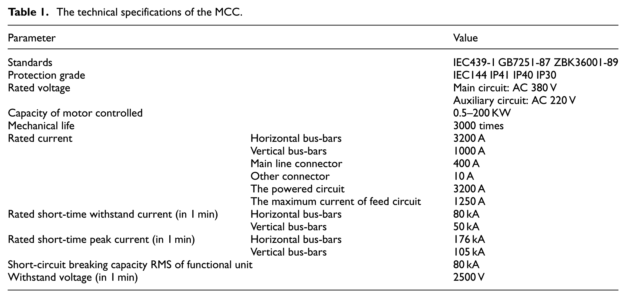
The MCC is GCK4 low-voltage drawer-type switch cabinet MCC. It is the combined closed structure, composed of a cabinet and drawer unit, and suitable for the power system with frequency of 50 Hz and rated voltage 380 V and below. The technical specifications are shown in Table 1. It is powered for hydrogen production plant by water electrolysis. According to different functions, the reliability block diagram is setup based on the actual circuit and shown in Figure 1.
The technical specifications of the MCC.
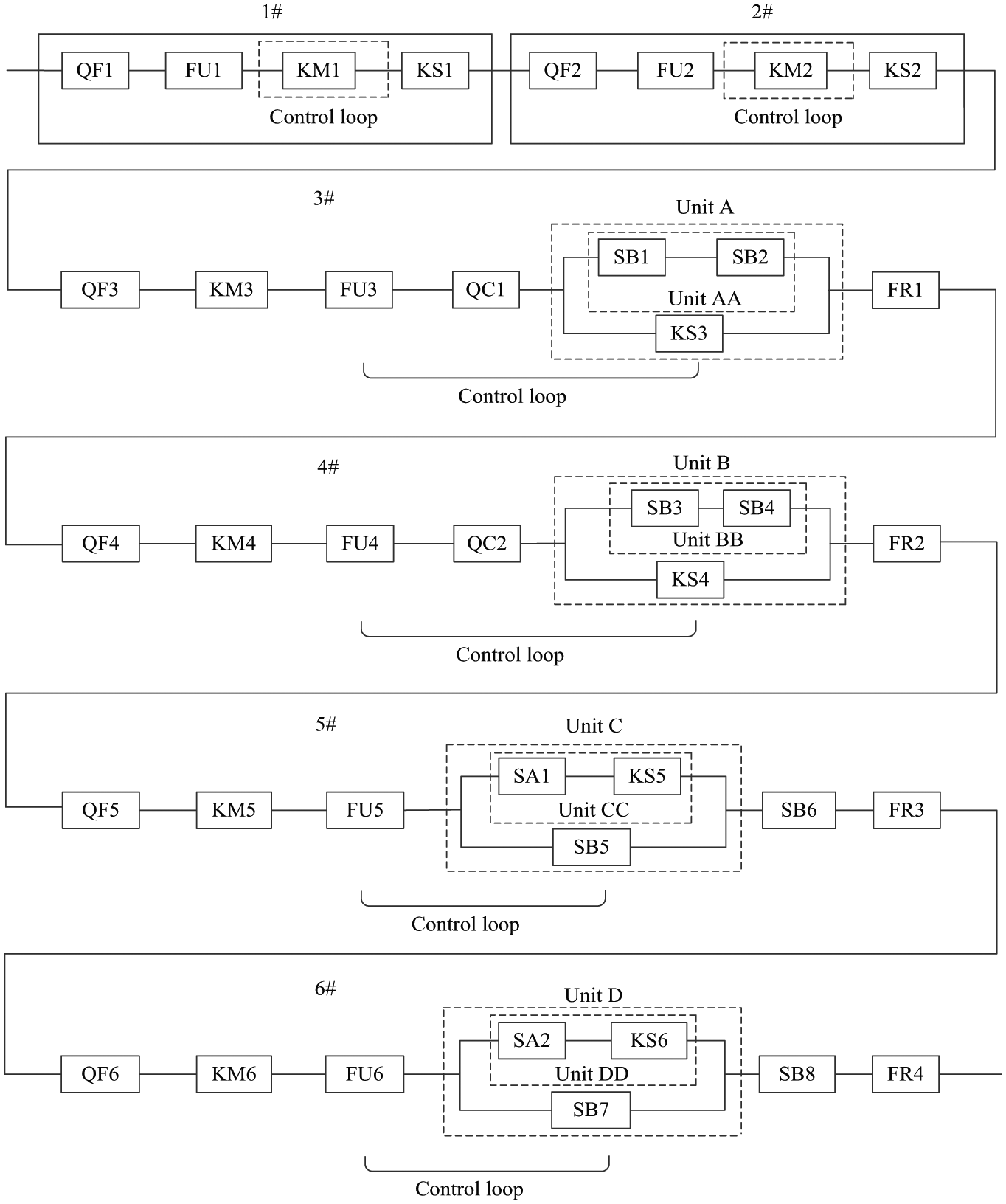
The reliability block diagram of the MCC.
In Figure 1, 1# and 2# are two dehumidifier circuits, 3# is electrolyte circulation circuit, 4# is the water feeding pump circuit, 5# is cooling fan circuit in tank room, and 6# is cooling fan circuit in distribution room. It can be observed that 1# and 2#, four components in series, have the same structure and components. 3# and 4#, 5# and 6# have the same structure and components. 1# and 2# subsystems are used to guarantee the gas by absorbing water. 3# and 4# subsystems are used to ensure the hydrogen production plant by water electrolysis. 3# and 4# subsystems are used to cool the gas.
The MCC is divided into six modules in series and continued divided into smaller units until the unit contains only components. According to reliability block diagram of the MCC in Figure 1, the hierarchical structure of the MCC is shown in Figure 2. It has five layers. The MCC is in the first layer, and the six modules are in the second layer. Unit A, B, C, and D are in the third layer. Unit AA, BB, CC, and DD are in the fourth layer.

Hierarchical structure of the MCC.
The parameter calculation of layers
After the hierarchy of MCC, it is necessary to calculate the parameters of every layer before the reliability assessment and management of MCC. The following formulas24,25 are used to obtain the parameters of every layer.
Formula (1) on the assumption that repair time is much less than mean time to failure is used for unit consisted of n components (

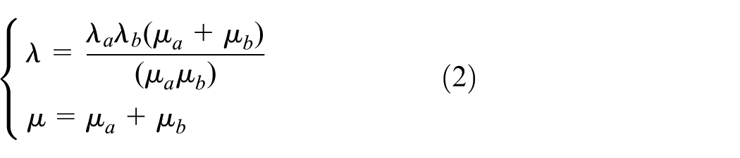
Formula (2) is used for parallel unit consisted of two different repairable components (
Units AA, BB, CC, and DD consisted of two components in series, thus formula (1) is used to calculate their failure rates and repair rates. Units A, B, C, and D consisted of two components in parallel. Therefore, formula (2) is used to calculate corresponding failure rates and repair rates. And then formula (1) is used to calculate the failure rates and repair rates of all modules.
Hierarchical Markov model of the MCC
Low-voltage switchgear is a repairable system. When it cannot work normally, the failure component has to be repaired or replaced with a new one to keep the device run normally. This is a cycling process of normal state, failure and normal state again after repairing that will not stop until it is not worthy, a random process of state transition that features Markov process, that is, the probabilistic behavior is independent of its history and depends only on the current state. While every component has constant failure rate and repair rate, a hierarchical Markov process can be used to analyze its reliability.
The top layer of the MCC
The top layer of the MCC which consisted of six modules in series has seven possible states (states 00–06). The states of MCC are illustrated in Figure 3.

All the states of the MCC.
In Figure 3, the modules of 1#–6# are all operational in state 00, only 1# has failed in state 01, only 2# has failed in state 02, only 3# has failed in state 03, only 4# has failed in state 04, only 5# has failed in state 05, and only 6# has failed in state 06. State 00 is the working state of the MCC, and states 01–06 are the failure states. The state transition diagram of the states is presented in Figure 4.
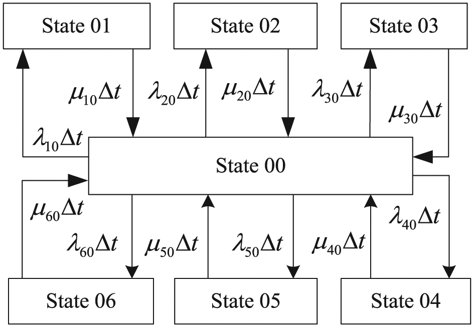
The state transition diagram of the states.
In Figure 4,
According to the state relations in Figure 4, the state transfer probability matrix

State transition density matrix of the MCC

where
pi(t), i = 0, …, 6 are state probabilities of the MCC and modules.
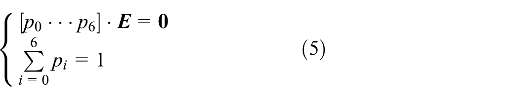
the steady-state probability of every state can be obtained.
Then, the steady-state availability of the MCC

The module and unit
Modules of 1#–6# are in the second layer. And the 5# and 6# modules have a more complex structure among the six. Therefore, the former is taken as an example here. The 5# module consists of five components and unit C in parallel. That is to say, it works if and only if all components and unit work. Therefore, it has only one working state (all the components are operational) and six unusable states caused by failures of QF5, KM5, FU5, unit C, SB6, and FR3, respectively. The state transition diagram of the states is presented in Figure 5.

The state transition diagram of 5# subsystem.
In Figure 5,
It denotes that

where
When

pij(t) is the state probability of the jth component of the ith module. Steady-state probabilities p51, p52, p53, p5C, p57, p58 are calculated by solving the following equations

Unit C, in the third layer, is a parallel system consisting of two different units. It has five states. Both unit CC and SB5 are operational in state 5C0, unit CC is operational and SB5 has failed in state 5C1, SB5 is operational and unit CC has failed in state 5C2, SB5 has failed and unit CC had failed in state 5C3, and unit CC has failed and SB5 had failed in state 5C4. States 5C0, 5C1, and 5C2 represent that the system is in working state, and states 5C3 and 5C4 show the failure states of the unit. The state transition diagram of the states is presented in Figure 6.
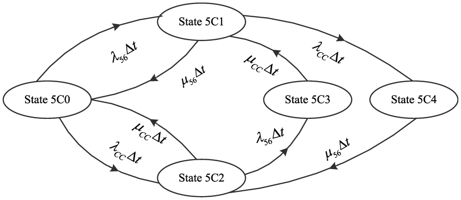
The state transition diagram of unit C.
In Figure 6,
According to the state transition diagram of unit C in Figure 6, the state transfer probability matrix

where
When

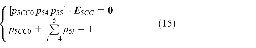
The steady-state probabilities p5C0, p5C1, p5C2, p5C3, p5C4 of unit C can be calculated by solving the following equations

Unit CC, in the fourth layer, is a series unit of two components SA1 and KS5. It has three states. Both unit SA1 and KS5 are operational in state 5C0, SA1 is operational and KS5 has failed in state 5C1, and KS5 is operational and SA1 has failed in state 5C2. State 5C0 is the working state, and the others are the failure state. The state transfer probability matrix

When

The steady-state probabilities p5C0, p5C1, p5C2, p5C3, p5C4 of unit CC can be calculated by solving the following equations
Finally, the reliability of other modules is analyzed based on hierarchical Markov model. And then steady-states probabilities of all components are obtained.
Reliability assessment and management of the MCC
The failure rates and repair rates of modules and units
The collected failure rates and repair rates of components in the MCC are summarized in Figure 7. Among the components, the failure rate of FU is the highest in Figure 7(a), followed by SB and SA. In Figure 7(b), the repair rate of SA is the highest, followed by FU and SB.

(a) The failure rate and (b) repair rate of component.
According to data in Figure 7, the parameter values of modules can be obtained by formulas (1) and (2), and they are summarized in Table 2.
The parameter values of modules.

Reliability assessment and management of the first and second layer
By data in Table 2, the state transition density matrix of the top layer for the MCC

When
By the results, it is observed that the probability of the MCC in working state is greater than 0.9972, which shows the high quality of the device. Steady-state probability of module in failure state is listed in Table 3.
Steady-state probability of module in each state.

From Table 3, it can be also observed that the probability of 3# and 4# modules (p3 = p4 = 5.3 × 10⁻⁴) are the highest among the six modules. They are the key modules affecting the reliability of the MCC. In the management process, they are the focus of monitoring objects.
Reliability assessment and management of module and unit
The state transition density matrix of 5# module

where
By solving equation (9), the steady-state probability of every state can be obtained
The state transition density matrix of unit C

By solving equation (12), the steady-state probability can be obtained

The state transition density matrix of unit C

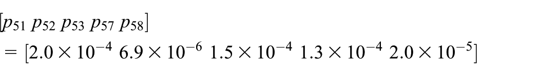
By solving equation (15), the steady-state probability can be obtained

Finally, the reliability of other modules is also analyzed based on hierarchical Markov model. And steady-state probabilities of components are summarized in Table 4.
Steady-state probabilities of all components.
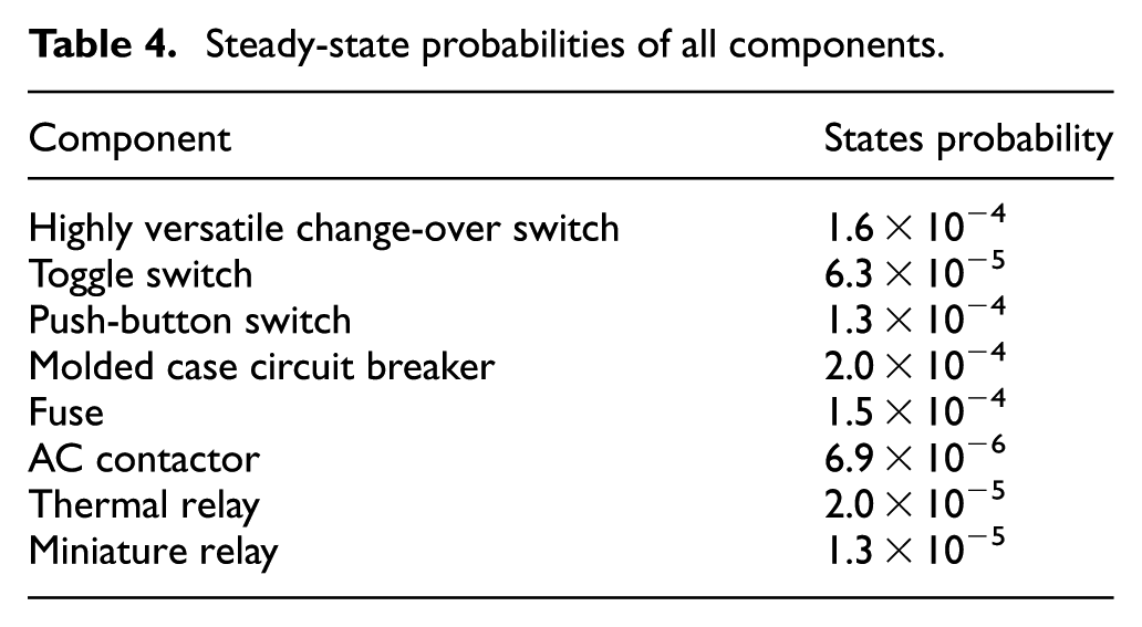
From Table 4, it can be observed that the highest probability of component in failure state is molded case circuit breaker, followed by highly versatile change-over switch.
Conclusion
The reliability assessment and management of MCC is introduced based on hierarchical Markov model. It can be summarized as follows.
By the first and the second layer, the availability is 0.9972, which shows the high quality of the MCC. And also, it is known that the 3# and 4# (p3 = p4 = 5.3 × 10⁻⁴) are key modules. By the other layers, the probabilities of components in failure states are got. According to the probabilities, it is observed that QF is the key component. Therefore, in the management process, circuit breakers, especially in 3# and 4# modules, require constant monitoring their operation. The results are beneficial to improve the reliability and select the optimal repair and management strategy for low-voltage switchgear and other repairable complex systems.
Hierarchical Markov process is convenient to locate the key module and component, and with a comprehensive evaluation of the failure rate and repair rate, which is helpful to device management.
Footnotes
Academic Editor: Joshua Ignatius
Declaration of conflicting interests
The author(s) declared no potential conflicts of interest with respect to the research, authorship, and/or publication of this article.
Funding
The author(s) received no financial support for the research, authorship, and/or publication of this article.