
Abstract
Due to the special characteristics of the space telerobot system (the dynamic coupling and the dynamic singularities), it is difficult for ground operators to directly operate or plan the orbital telerobot to accomplish the capture task. This article proposes an autonomous trajectory planner under the teleprogramming framework for space telerobots to capture space debris, where the direct optimization method is adopted to obtain smooth and singularity-avoiding joint trajectories. First, the motion planning problem is formulated as a constrained optimization problem, where the precise capture is set as the optimization objective and the base disturbance and the physical limitations (joint position, velocity, and acceleration) are set as constraints. Then, the parameterization and normalization treatments and the penalty function method are adopted to handle constraints and determine the feasible region of the undetermined parameters. Furthermore, an autonomous trajectory planner based on the forward differential kinematics and the differential evolution algorithm is developed to plan the feasible joint trajectories. Finally, the simulation of a space telerobot equipped with a 7-degree-of-freedom manipulator capturing floating debris is conducted to verify the effectiveness of the proposed planner.
Keywords
Introduction
The population of human-generated space debris is growing in low Earth orbit (LEO) year after year, which poses a serious threat to the current operating satellites. 1 Therefore, active debris removal (ADR) has been an inevitable mission for the future space environment. As a promising solution, space robots are developed to substitute astronauts to execute some on-orbit servicing (OOS) tasks. 2 Unlike industrial robots, most of space robots should be faced with various sophisticated, non-repetitive, and unfamiliar tasks. Fortunately, teleoperation, as one of the most important robotic technologies, extends human’s manipulation, reasoning, and decision-making capabilities to remote robots, which makes these tasks tractable. 3
The direct control mode is the most successful approach in space applications, where the operator remains in the control loop at any time and provides the continuous control signals. For example, in the Canadarm2 and Japanese Experiment Module Remote Manipulator System (JEMRMS) systems, the operators use joysticks to control them to accomplish ordinary tasks in the International Space Station (ISS). 4 The first ground-orbit-based telerobot system, Robot Technology Experiment (ROTEX), also adopted the unilateral teleoperation, where a predictive simulator was employed to compensate the communication time delay (5–7 s). 5 The Engineering Test Satellite VII (ETS-VII) also carried out the bilateral teleoperation by a master–slave system with a communication time delay of 7 s. 6 Besides, based on the particular communication infrastructures, the German Aerospace Center (DLR) accomplished the OOS ground verifications using the bilateral teleoperation, where the round-trip delay is about 620 ms. 7 Although the ROTEX and ETS-VII projects are successfully performed in the case of large time delay, to some extent, it largely depends on the fact that operators are well acquainted with the tasks in advance.
In fact, it is not easy to apply the direct control mode in the unfamiliar ADR tasks. There are twofold reasons: (1) the round-trip time delay (more than 1 s) may lead to the result that the feedback signal cannot be received in time, which may affect the stability of the direct control system 8 and (2) the special characteristics of the space robots (e.g. the floating base dynamics) lead to the situation that they are difficult to be operated. 9 So far, the fully autonomous operation (without human intervention) is still beyond the state of the art of space robotics. For addressing the communication delay, the teleprogramming approach is proposed by Funda et al., 10 which, as a viable form of the supervisory control, provides a concise framework for controlling the semi-autonomous space robot system. In the teleprogramming framework, the task is first done in the simulation environment; then the operational steps are translated into high-level commands and sent to the remote zone to be executed by semi-autonomous systems under the supervision of operators.
On the other hand, the special characteristics of space telerobot systems and space operational conditions should be taken into account in the capture task. For this satellite-manipulator system, one of the most distinctive features is the dynamic coupling, 11 that is, the motion of the manipulator has a direct physical feedback on its base and the coupling motion of the base will affect the operation performance of the manipulator. Unlike the base-fixed robots,12,13 the space robots cannot form the accuracy kinematics at the position level. Thus, it is difficult for operators to directly operate space telerobots to capture debris. The motion planning is a necessary prerequisite in the capture task. The early coordinated control method14,15 employed the jet thrust system to compensate the reaction of the manipulator so that the space robot could behave as a ground-fixed robot. However, the large consumption of physical fuel and the influence (that the compensating jet may blow away the debris) are the major drawbacks in applications. In general, after space robots reached the rendezvous zone, it is preferable to change them into the free-floating mode (the position and attitude systems of bases were shut off) to execute tasks. 2 In this working mode, the space robot is an underactuated system. As for the studies of free-floating space robots, Umetani and Yoshida 16 proposed the generalized Jacobian matrix (GJM) to describe the differential mapping relationship from the joint space to the end effector in the working space. Nakamura and Mukherjee 17 analyzed the nonholonomic property of free-floating space robots and proposed a bidirectional approach to plan the manipulator and the base simultaneously. Dubowsky and Torres 18 proposed a technique called enhanced disturbance map (EDM) to plan the manipulator with minimizing the base disturbance. Nenchev 19 proposed the concept of reaction null-space (RNS) to plan the kinematical redundant manipulator to achieve a zero disturbance on the base. However, the dynamic singularity 20 (i.e. singularities of the GJM) is a specific and severe issue for space robots. Here, the singularities of the GJM are related not only to the geometry parameters but also to the inertia parameters, with the result that the singularity configurations cannot be predicted solely from the joint space. Thus, it is hard for operators to plan a space telerobot like a base-fixed robot.
In view of the above, this article aims at developing an autonomous trajectory planner under the teleprogramming framework for supporting the ground operators. Here, the planning problem is treated as a constrained optimization problem. The objective is set to realize the precise point-to-point capture. Meanwhile, as the directional antenna on the base needs to be kept in a certain range for the data transmission, the attitude disturbance of the base is considered as an inequality constraint. Besides, the physical constraints in joint space are also considered in the motion planning. Based on the parameter optimization technique, the forward differential kinematics, and the differential evolution (DE) algorithm, the autonomous planning procedures are developed to plan joint trajectories.
The rest of this article is organized as follows. The motion equations of the space telerobot are introduced in section “Motion equations.” The teleprogramming control framework and the capture task analysis are discussed in section “Analysis of the capture task.” The design details of the autonomous trajectory planner are described in section “Autonomous trajectory planner.” The simulation of a space telerobot equipped with a 7-degree-of-freedom (DOF) manipulator capturing space debris is presented in section “Simulation.” Finally, the conclusions are provided in section “Conclusion.”
Motion equations
As shown in Figure 1, the space telerobot system has n + 1 rigid bodies, where the satellite base is body 0 and the manipulator contains the rest n bodies (connected by the single-DOF joint). A virtual 6-DOF joint is assumed to describe the connection relationship between the base and the earth. Before discussing the kinematics of space telerobots, some symbols and variables used in the following are defined in Table 1. Besides, the common assumptions are given as follows: (1) there are no external forces impacting on the space telerobot and (2) the initial linear and angular momentum of the space telerobot is zero.
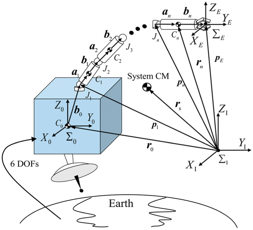
The general diagram of the space telerobot.
Definitions of symbols and variables used in this article.

Coupling motion equation
Based on assumption (1), it can be deduced that the linear and angular momentum of the system is conserved. Furthermore, the dynamic coupling equation between the manipulator and the base can be derived from the momentum conservation law.
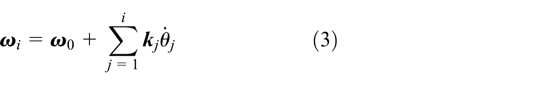
Here, the total linear and angular momentum of the whole system,


where
Based on assumption (2),

where the intermediate parameter matrices are defined as follows


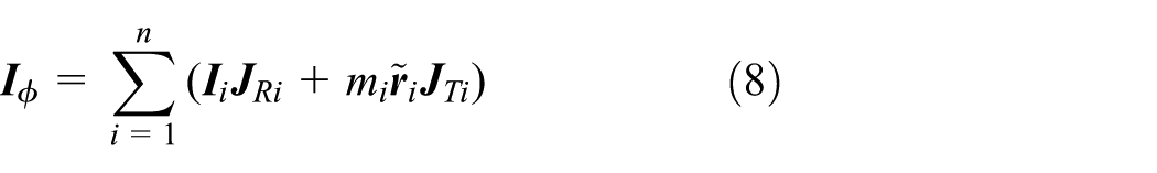

and
Furthermore, let

And, equation (4) can be modified as follows
where the intermediate parameter matrices are defined as follows
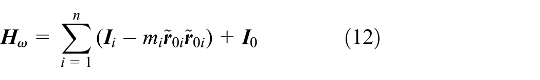

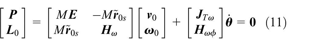
Then, the coupling motion equation can be obtained as follows
where
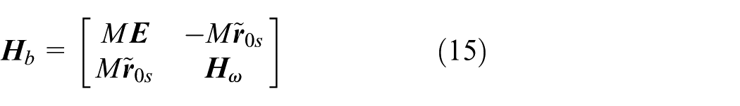

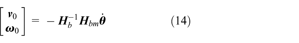
Furthermore, define

where
Here, the base attitude is represented by X–Y–Z Euler angles, that is,
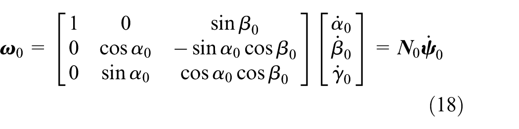
Combining the lower part of equation (17) with equation (18), the base attitude kinematics in X–Y–Z Euler angles can be derived as follows

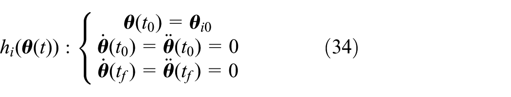
Furthermore, the attitude of the base at the final time

where
Kinematic equation of the space telerobot
As shown in Figure 1, the position vector of the end effector in the inertia frame is defined as follows

Differentiating equation (21) with respect to time, the linear velocity of the end effector can be derived as follows

Besides, the angular velocity of the end effector is expressed as follows

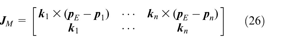
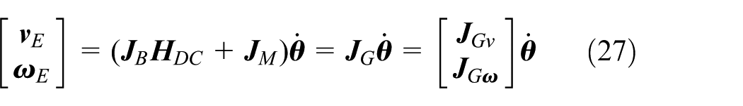
Combining equations (22) and (23), the general differential kinematics of the free-flying space telerobot can be expressed as follows

where

where
where the coefficient matrix
Furthermore, the position of the end effector at the final time

where

And, the attitude of the end effector at the final time

where
Analysis of the capture task
Brief of the space teleprogramming framework
The capture task is a necessary step in the ADR mission, where the task profile of the space telerobot capturing a floating debris in LEO is illustrated in Figure 2(a). The communication data should be transmitted via one or more tracking and data relay satellites (TDRS) in geosynchronous orbit (GEO), which is the main reason why the cumulative time delay is several seconds. 4 As is mentioned above, the teleprogramming control provides an achievable control framework to get rid of the communication delay. In fact, it had been successfully performed in the ROTEX project. 5 In Figure 2(b), a general control framework is concluded to describe the workflow of teleprogramming robots, 10 which consists of three levels: the decision-making level, the analysis and planning level, and the execution level. Meanwhile, it contains three control loops: the main control loop (the supervisor loop), the simulation loop, and the remote autonomy loop. The ground operator in decision-making level defines the tasks, interacts with the simulation system, monitors the feedback from the simulation loop and main loop, and updates the commands. The ground simulator provides a virtualized operating environment where the task can be performed by operators or the ground controller. Moreover, the ground controller continuously records the operating information and translates them into symbolic or normalized-value motion instructions. As for the semi-autonomous platform, that is, the space robot, it takes charge of the real-time hardware servo control to execute the motion instructions.
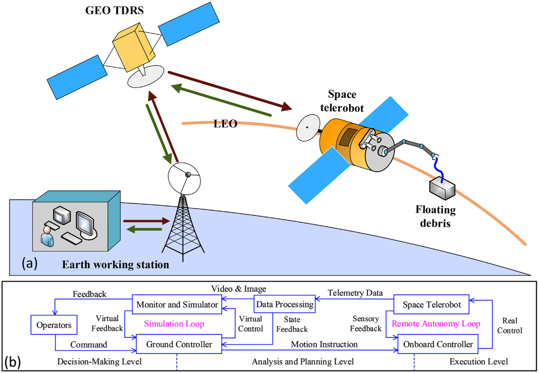
The space teleprogramming robot: (a) the schematic diagram and (b) the control framework.
Task analysis and problem statement
In this subsection, the capture task is analyzed in detail to make the problem clear. As shown in Figure 2(a), before the manipulator executes the operation, the space telerobot has been navigated to an appropriate rendezvous zone where the manipulator can reach the debris, and the on-board vision devices can accurately measure the position and attitude information of the debris. Then, the space telerobot sends the measured information to the earth working station which takes charge of planning feasible trajectories in joint space to meet the grasping constraints. Here, the grasping constraints can be described by the following: (1) grasping position:
Meanwhile, in order to guarantee the telemetry data transmission, the attitude disturbance of the base antenna should be controlled within a certain range. Here, the change of the base attitude,
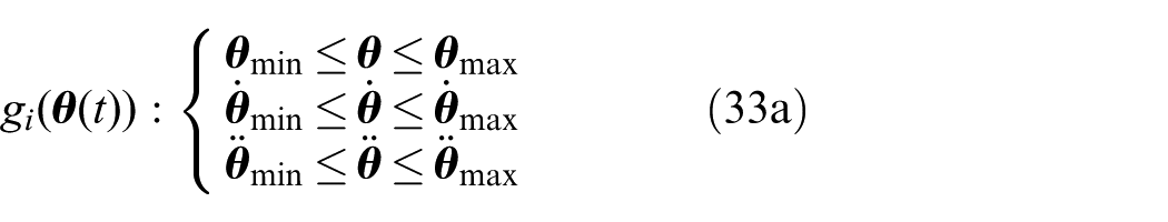
In addition, the motion performance of the manipulator system largely depends on the physical constraints in joint space. So, the physical constraints should be considered in the trajectory planning, which are described as follows: (1) joint position:
Principally, the planning problem for which joint trajectories need to be determined to satisfy constraints can be formulated as a constrained optimization problem as follows:
To determine joint functions:
To minimize the objective function

where


where
Subject to the inequality constraints

Subject to the equality constraints
where
Autonomous trajectory planner
Through the above analysis, the motion planning problem can be converted into a constrained optimization problem. Some methods24,25 based on the optimal control theory are proposed to solve this problem, where the planned trajectories can satisfy the equality and inequality constraints, but sometimes, the trajectories are not smooth enough. Another solution is the direct optimization method,4,26 which adopts the parameter optimization technique and search algorithms (e.g. sequential quadratic programming (SQP), 27 genetic algorithm (GA), 28 and particle swarm optimization (PSO) 29 ) to derive feasible trajectories. Compared with the first method, the second method is more flexible and targeted. Therefore, an autonomous planner based on the direct optimization method is developed to generate feasible trajectories for space telerobots to execute the point-to-point grasping task.
Parameterization of the joint trajectories
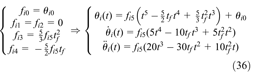
Many functions can be used to parameterize the joint trajectories, such as the polynomial function, Bézier curve, and other functions. Here, the polynomial functions are employed to parameterize the joint position, velocity, and acceleration trajectories as follows

where
where
Normalization treatment
After the parameterization treatment, a feasible searching region can be defined through the normalization treatment. 30 Here, the physical constraints are regarded as the criteria to determine the searching boundary. First, the normalized time is defined as follows
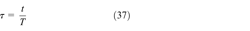
where
Substituting equation (37) into equation (36), the corresponding joint functions can be written as follows

where

Furthermore, since the normalized time
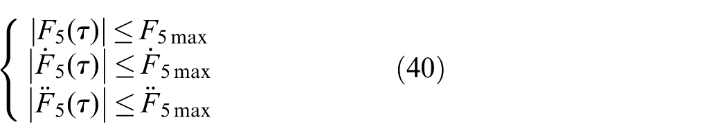
where


where
Penalty function method
After the normalization treatment, the inequality constraints in joint space are released. The rest inequality constraints are the attitude disturbance constraints of the base, where the penalty function method 31 is adopted to handle the attitude disturbance constraints as follows


where
Furthermore, by merging equation (31) and equation (43), a new objective function can be formulated as follows

As
Synthesizing the parameterization, normalization, and penalty function treatments above, the constrained optimization problem can be further converted into an unconstrained optimization problem as follows:
To determine:
To minimize:
The feasible region
DE
As one of the most efficient population-based evolutionary algorithms, DE is an improved version of GA and has been applied in many practical problems. 32 For its simple searching mechanism, excellent convergence property, and suitability for parallelization, the DE algorithm is employed to search the optimal joint parameters in the capture task.
In the DE algorithm, a parent individual from the current generation is set as target vector; a mutant vector obtained by the differential mutation operation is named donor vector; an offspring vector generated by mingling the target vector and the donor vector is called trial vector; and through the competition between the target vector and the trial vector, DE realizes the overall evolution of the population.
Specifically, the DE/rand/1/bin algorithm
33
is adopted here, and its detailed steps are introduced as follows. For a n-dimensional optimization, first initialize a population of NP individuals

where
After obtaining the donor vector, the crossover operation will be carried out to maintain the diversity of the population. Here,

where
Next, the selection operation will determine whether the target vector or the trial vector survives to the next generation, which can be expressed as follows

where
Planning procedures
The planning procedures are designed based on the forward differential kinematics and the DE algorithm, as outlined in Figure 3. The main merit of the proposed planner is that the calculation of the GJM inversion is not involved in the planning process, so the proposed planner can avoid the dynamic singularity, and the planned trajectories are free of singularities. Furthermore, the detailed explanations of each step are provided as follows:
Step 1. Parameterization of the joint trajectories
According to equation (36), the fifth-order polynomial function is adopted to parameterize the joint trajectories.
Step 2. Parameter settings and the initialization
Here, the parameters can be divided two categories: the space telerobot parameters and the control parameters of DE. The first category contains the following: the initial position of the base
Step 3. Judgment of the maximum iterations
If the current number of iterations is less than the maximum iterations, the planning procedures will continue optimizing, or it will output the optimal joint trajectories.
Step 4. Calculation of the velocity terms of the base and the end effector
The velocity term of the base can be calculated using equation (17), and it will be used to construct the GJM for calculating the velocity term of the end effector, that is, equation (27).
Step 5. Calculation of the base attitude and the end effector pose
The base attitude can be calculated using equation (20), and the end effector pose can be calculated using equations (28) and (30).
Step 6. Calculation of the objective function
The objective function can be calculated using equation (44).
Step 7. Judgment of the grasping constraints
If the value of the objective function is less than 1, it could be deduced that the current joint functions can satisfy the grasping constraints.
Step 8. Record the satisfactory joint trajectory functions and output the optimal candidate
The satisfactory results will be recorded in the database, and the optimal candidate will be output when the number of iterations reaches the maximum.

Planning procedures.
Simulation
In this section, a space telerobot with a 7-DOF manipulator is studied to verify the trajectory planner. Each body coordinate of the telerobot system is defined in Figure 4. The Denavit–Hartenberg (D-H) parameters of the 7-DOF manipulator and the dynamic parameters of the system are provided in Tables 2 and 3, respectively.

The space telerobot system.
The D-H parameters of the 7-DOF space manipulator.

D-H: Denavit–Hartenberg; DOF: degree of freedom.
Dynamic parameters of 7-DOF space manipulator.

DOF: degree of freedom; EE: end effector.
The pose information of the debris is assumed as follows:
Joint position

2. Joint velocity

3. Joint acceleration

Moreover, in this task, the execution time T is set as 20 s. According to equation (42), the boundaries of the undetermined parameters
After the iterations, the satisfactory results are obtained as follows: the optimal candidate:
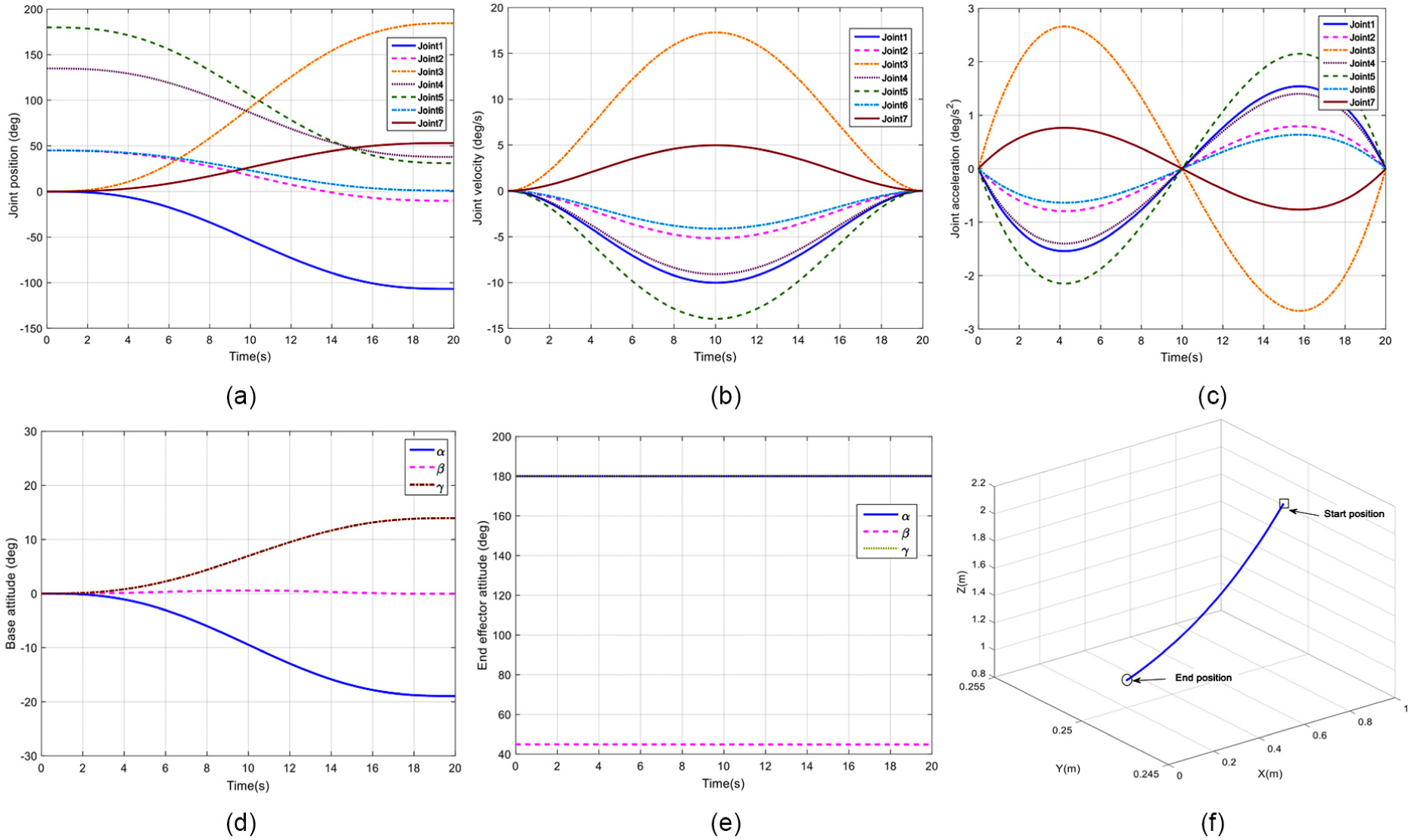
The simulation results: (a) joint position, (b) joint velocity, (c) joint acceleration, (d) base attitude, (e) end effector attitude, and (f) end effector position.
Conclusion
For overcoming the issues of the large latency and the space robot characteristics (dynamic coupling and the dynamic singularities) in the task of capturing space debris, a novel autonomous trajectory planner under the teleprogramming framework is proposed to provide an autonomous planning skill for the ground operators.
In this article, the motion planning problem is formulated as a trajectory optimization problem, where the grasping position and attitude are set as the objective functions and the base disturbance and the joint limitations are set as the constraints. The fifth-order polynomial function is used to parameterize each joint trajectory for obtaining smooth joint trajectories. By normalizing the execution time, the feasible region of the free parameters can be determined. Besides, the base disturbance constraints are handled by the penalty function method. The planning procedures based on the forward differential kinematics and DE algorithm are developed to derive the feasible joint functions. Another advantage of this planner is that it avoids calculating the GJM inversion, so this method is free of dynamic singularities. Furthermore, the proposed planner is verified by simulation. The simulation results show that the planned trajectories are smooth enough and the end effector can reach the grasping position and attitude. In the further work, we will concentrate on the visualization display of the capture process.
Footnotes
Academic Editor: Zhaojie Ju
Declaration of conflicting interests
The author(s) declared no potential conflicts of interest with respect to the research, authorship, and/or publication of this article.
Funding
The author(s) disclosed receipt of the following financial support for the research, authorship, and/or publication of this article: This study is supported by Basic Research Fund of China Manned Space Engineering, the Key Research Program of the Chinese Academy of Sciences (Y4A3210301), the National Science Foundation of China (51175494, 51505470, and 51575412), and the State Key Laboratory of Robotics Foundation.