
Abstract
Noninvasive channel healing is a new idea to repair the broken pipe wall, using external electric fields to drive iron particles to the destination. The repair can be done in the normal operation of the pipe flow without any shutdown of the pipeline so that this method can be a potentially efficient and safe technology of pipe healing. However, the real application needs full knowledge of healing details. Numerical simulation is an effective method. Thus, in this research, we first established a numerical model for noninvasive channel healing technology to represent fluid–particle interaction. The iron particles can be attached to a cracking area by external electrostatic forces or can also be detached by mechanical forces from the fluid. When enough particles are permanently attached on the cracking area, the pipe wall can be healed. The numerical criterion of the permanent attachment is discussed. A fully three-dimensional finite difference framework of direct numerical simulation is established and applied to different cases to simulate the full process of channel healing. The impact of Reynolds number and particle concentration on the healing process is discussed. This numerical investigation provides valuable reference and tools for further simulation of real pipe healing in engineering.
Introduction
Piping systems are very important in petroleum transportation engineering. After long-period operations, the pipelines usually face the problem of corrosion, which causes cracks on the pipe wall and increases pipelining risks. 1 Standard treatment of this problem in engineering currently is repair or replacement of the damaged segments, which involves high capital cost. 2 This requires shutdown of the whole transportation system, including the pipeline and affiliated pumps, heat exchangers and power systems. Interruption of petroleum transportation has great impact on downstream oil refinery factories and users, resulting in large economic loss usually. For pipelines transporting waxy oil, whose pour point is higher than regular oil, the oil gels because of lower temperature during the period of shutdown. Gelled oil blocks the pipeline so that restart fails to bring second hazard to the pipeline. Expensive treatment, economic loss and second hazard motivate to derive a strategy of pipeline repair without shutdown. Zohdi proposed a concept of “noninvasive” pipe healing using charged iron particles guided by electromagnetic field from the exterior of the pipeline, which can heal the pipe wall resulting in no shutdown so that the cost may be largely reduced. However, this idea is only in a primary stage with so many issues not being addressed, including particle attachment and detachment, particle–fluid–wall interaction in an electronic field, and so on. Some results on biological systems can be a good reference.3–5 Also, some studies have been carried out by Zohdi and colleagues,6,7 focusing on particle adhesion to walls, but the simple notion of a detachment stress threshold may be inadequate. Recently, Mukherjee et al. 8 provided a numerical framework for the idea of the noninvasive pipe healing technique. They treat the particle–wall interaction very well in laminar flow. The flow status in real pipelines for petroleum engineering must be turbulence. Therefore, we propose a numerical model for channel healing under the condition of three-dimensional turbulent flow and do the direct numerical simulation (DNS) in this paper.
Numerical model
Fluid flow model
The pipeline transporting petroleum is usually as long as hundreds to thousands of kilometers. A simplification in engineering is done using cross-sectional average velocity instead of local velocity so that calculation can be done for this length of pipeline. This assumption is not suitable for the simulation of pipe healing because the spatial distribution of flow field, which should be considered, is neglected. Thus, a fully three-dimensional (3D) flow model with corresponding governing equations should be established. However, the 3D model requires a dense mesh to resolve small eddies, so that the total grid number for a several-kilometer-long pipeline can be too large to exceed the storage of computers (even if super computers). Hence, flow domain must be simplified first. Limited shorter domain with periodic boundary condition is a good choice, as shown in Figure 1. The boxes with symbol “+” and “–” represent the positive and negative electrodes installed outside of channel walls. They are located on the center of x–z plane. The computational domain has side lengths of 7.5h, 2h, 2.5h in the x, y, z directions, respectively (h is the half height of the channel). The crack is assumed at the central area with the dimension of 1.5h × 0.04h × 0.5h (x × y × z) on the bottom wall. Periodic flow boundary condition is imposed on the x and z directions.
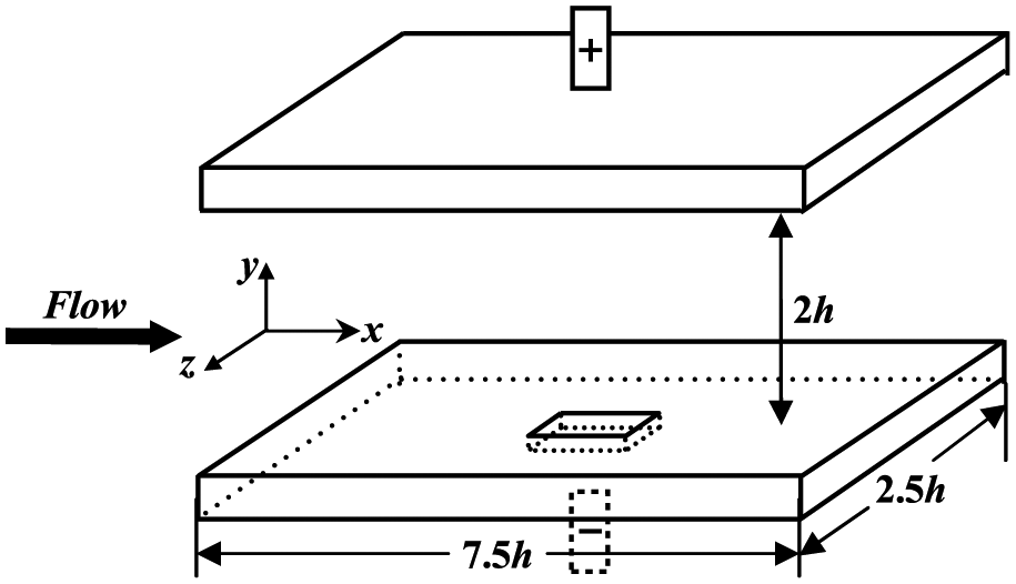
Illustration of channel flow with external electric field.
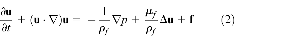
In this computational domain, the governing equations describing the three-dimensional, unsteady incompressible viscous fluid flow are continuity equation and Navier–Stokes (N-S) equation in tensor forms:
Continuity equation

N-S equation
where

where

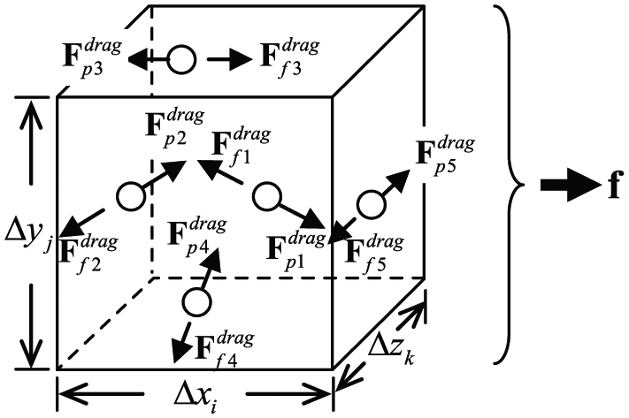
Illustration of fluid–particle interaction in one control volume.
Particle motion model
The above discussions show it is important to deal with the fluid–particle interaction force
Particle motion equation

Drag force
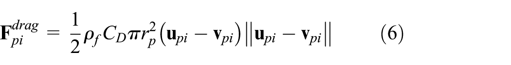
where

Stokes’ drag law can be used for the calculation of

Stokes’ law only satisfies

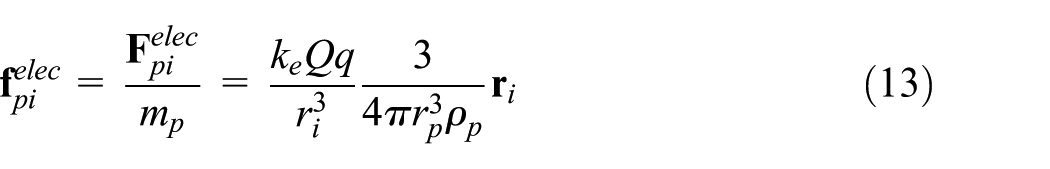
The electric force imposed on the ith particle can be calculated from the definition of electrostatic force
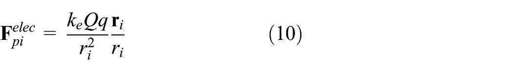
where
It is not necessary to calculate

where

where
Particle–wall interaction model
Particle-wall interaction includes two parts: attachment on the wall driven by electrostatic force and collision with wall. For the first part, an energy criterion is proposed for the accumulation of particles: a particle can be accumulated on the target wall if the electrostatic energy is larger than the momentum energy of the particle. In this article, only the y direction is the wall-normal direction so that only the component of velocity in this direction is considered in the momentum energy

where

If
For the second part, elastic collision is the simplest assumption. However, it does not reflect the real collision which contains energy lost. Elastic collision without energy loss may also cause the particles take periodic motion between the target wall and the bulk flow, so that no particles can be accumulated on the wall. Thus, nonelastic collision is considered

where
Dimensionless governing equations
All the governing equations are nondimensionalized using the following dimensionless variables

where the superscript (+) and (*) denote the dimensionless variables;
Dimensionless flow equations


where
Dimensionless particle motion equations


Dimensionless electrostatic energy on the particle positions

The kinetic energy of particles after collision with walls

where

Numerical results of channel healing
The numerical model is solved by the fractional step method with grid number 64 × 64 × 64 and dimensionless time step
First, we should check the flow status. The mean velocity profiles for the case Reτ = 10 and Reτ = 150 are shown in Figure 3. It is obvious that the mean velocity profile for the case Reτ = 10 is far below the turbulent three layers, 10 while the mean velocity profile for the case Reτ = 150 agrees very well with the typical three-layer-mean-velocity profile of turbulent flow. Moreover, the bulk mean velocities (Um+) and the bulk mean Reynolds number (Rem) are listed in Table 1. Rem for the cases Reτ = 10 and Reτ = 150 are 67 and 4443, respectively. Thus, the two designed cases represent laminar flow and turbulent flow in the real pipeline.

Mean velocity profile of fluid flow under different friction Reynolds number.
Bulk mean velocity and Reynolds number.

Second, it is important to study the motion of particles and their influences on the flow field in the healing process, which can clarify the influence of the noninvasive healing method on the transporting fluid in pipeline. From the left columns in Figures 4–7, we can see that the flow field does not change much under different numbers of particles and different Reynolds numbers. This indicates that the noninvasive healing method is not sensitive to the inputting particle numbers and does not apparently affect the flow field, because of which the fluid transportation is not affected by this healing method, which is the main advantage of this method that has been verified by numerical results.
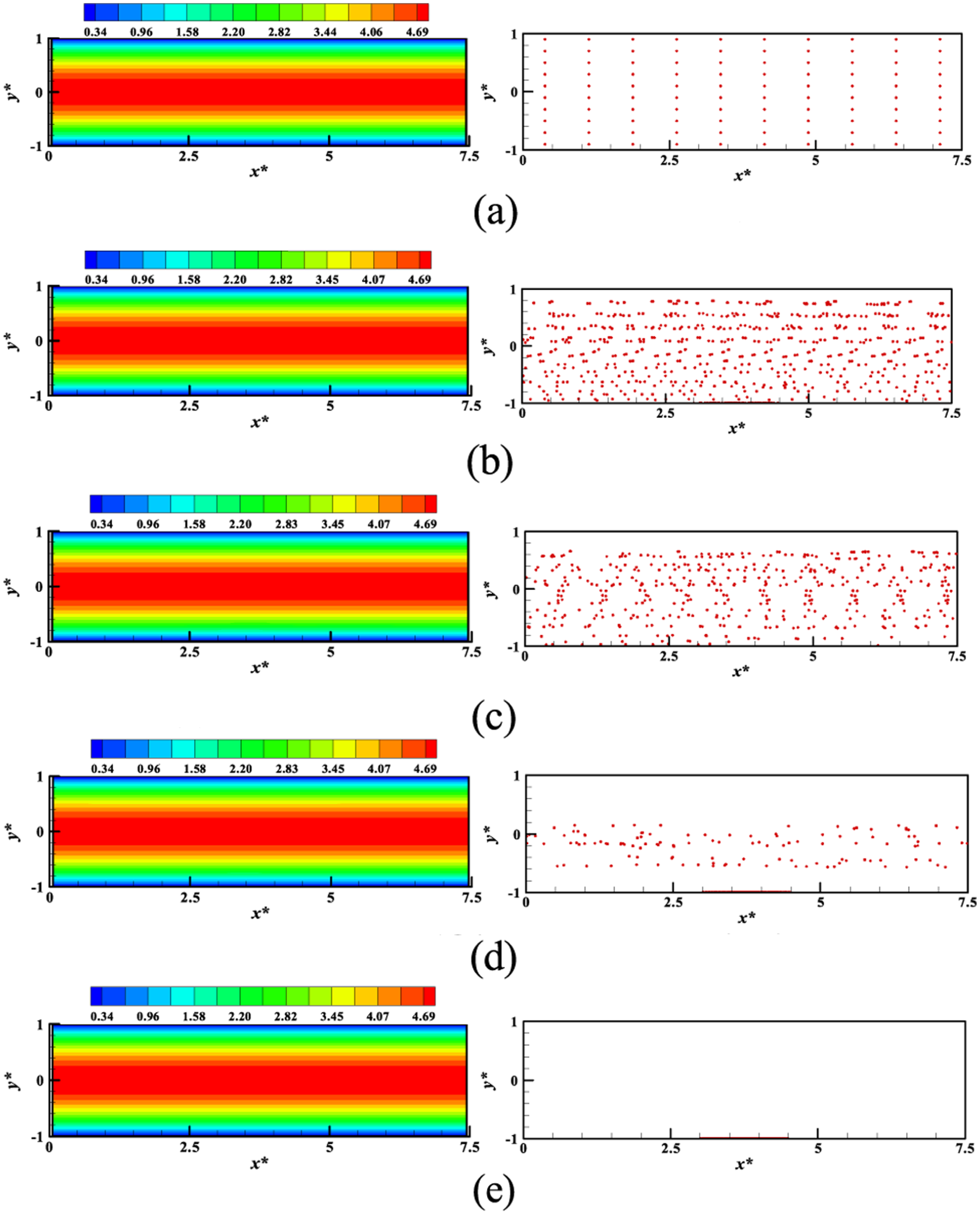
Flow field (left) and particle positions (right) at different moments of channel healing in laminar flow (1000 particles). a) 0

Flow field (left) and particle positions (right) at different moments of channel healing in laminar flow (10000 particles). (a) 0

Flow field (left) and particle positions (right) at different. (a) 0

Flow field (left) and particle positions (right) at different moments of channel healing in turbulent flow (1000 particles) moments of channel healing in turbulent flow (10000 particles). (a) 0
Comparing Figure 4 with Figure 6, we find that the pipe wall cannot be healed for laminar flow and turbulent flow inputting 1000 particles because the number of particles is not enough to fill the crack. This can be expected according to the volume of particles and the volume of the crack. However, the accumulation of the 1000 particles takes a much longer time than the accumulation of 7166 particles for inputting 10000 particles, for both the laminar flow and turbulent flow (Figures 5 and 7). This phenomenon shows that higher concentration of particles is helpful for channel healing. The reason is that more frequent collisions in higher concentration make the particles more easily overcome the resistance of fluid to reach the wall. Thus, high concentration of particles should be used in the real noninvasive healing process.
It can be seen in Figures 5 and 7 that the final healing time for the same inputting 10000 particles is much shorter in turbulent flow than in laminar flow. The number of accumulated particles in the whole process is shown in Figure 8 (NP is the number of accumulated particles). It is further verified that the particles are accumulated much faster in turbulent flow field than in laminar flow field at any moment. Their total dimensionless time is about 3.4 and 49.4, respectively. Turbulent flow can accelerate the healing process about 15 times. This is probably because the strong convection in turbulence makes the particles have larger velocity to overcome the flow resistance in the wall-normal direction more easily. Therefore, a high Reynolds number should be used for faster healing.
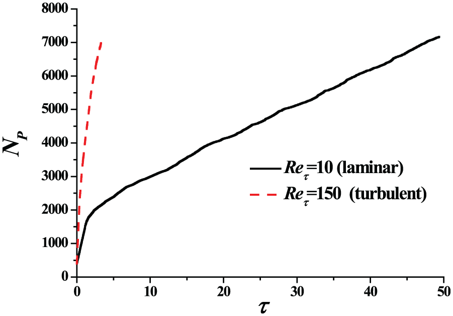
Healing time under different friction Reynolds numbers when inputting 10000 particles.
Conclusion
A numerical model is established for the new concept of channel healing via adding small iron particles driven by an external electric field. Fluid–particle interaction in electric field and particle–wall interaction are discussed in this model. A criterion is proposed for numerically judging channel healing according to the balance of electrostatic energy and momentum energy. The direct numerical simulations are made under different numbers of particles (1000 and 10000) and different flow status (Reτ = 10 for laminar flow and Reτ = 150 for turbulent flow). The numerical results show that the fluid transportation process is not affected in the healing process, verifying the noninvasive advantage of this kind of healing method. Key parameters of the noninvasive healing are studied. Higher concentration of particles and higher Reynolds number are helpful for faster channel healing because the two factors make the particles have more frequent collisions and higher convection due to which they have much larger velocity to overcome the wall-normal resistance from the fluid.
Footnotes
Handling Editor: Filippo Berto
Declaration of conflicting interests
The author(s) declared no potential conflicts of interest with respect to the research, authorship, and/or publication of this article.
Funding
The author(s) disclosed receipt of the following financial support for the research, authorship, and/or publication of this article: This work has been supported by National Natural Science Foundation of China (NSFC) (No.51576210), funding from King Abdullah University of Science and Technology (KAUST) through the grant BAS/1/1351-01-01 and Science Foundation of China University of Petroleum-Beijing (No. 2462015BJB03, No. 2462015YQ0409, No. C201602).