
Abstract
Three-dimensional metal particle flow simulation during the whole rolling process for 60 kg/m heavy rail was accomplished by explicit dynamic finite element method and modified updating geometric method. A finite element model, physical parameters of U71Mn, and parameter setting of simulation were introduced in detail. The metal flow rules of typical metal particles in rolled stock cross-section during the whole heavy rail rolling were obtained. Meanwhile, the continuous casting slab with artificial surface cracks, referred to as “circle” holes, was rolled in actual production line of Wuhan Iron and Steel (Group) Company. The finite element method calculated results of cross-sectional metal particles for U71Mn heavy rail are in good agreement with the experimental ones. It is shown that the explicit dynamic finite element method and modified updating geometric method can be used effectively to analyze the metal particle flow during the whole heavy rail rolling process.
Introduction
With the rapid development of high-speed railway transportation, the world’s railway technology is developing towards automatic traction, high-speed and heavy load. 1 Meanwhile, surface defects originating from steel making, continuous casting, and/or heavy rail rolling are often present in heavy rail final products. The market demand for heavy rail without any defects has increased.2–4 Therefore, understanding the metal flow behavior in the process of heavy rail rolling becomes very important. Heavy rail rolling has characteristics of a lot of rolling passes and section grooves, complex cross-sectional shape, large velocity, difference of roll, and concurrence of direct pressure and lateral pressure in groove. So, heavy rail rolling is extremely non-uniform plastic deformation. Theoretical analysis is very difficult to accurately find out the metal flow in the process of producing heavy rail. Physical simulation, such as trial rolling, is time-consuming, high cost, and hard to do quantitative analysis and get mathematical rules. 5 With the rapid development of computer technology, numerical simulation method has become an important tool for rolling theory research. Finite element method (FEM) was widely applied in solving hot rolling problems. For example, an explicit dynamic FEM and updating geometric method was used by Yu et al. 6 to investigate slab deformation behavior during the multi-pass vertical-horizontal (V-H) rolling process. M Glowacki7,8 and Guerrero et al. 9 used generalized plane-strain method and two-dimensional (2D) finite element formulation to simulate the rolling process of rail and shape steel in order to predict the metal flow and heat transfer and analyze the roll-pass design. A three-dimensional (3D) finite element model of U75V heavy rail in UF finishing rolling of universal rail rolling line was established by Tan and Jia 10 to study the characteristics of metal flow and deformation of the U75V rolled stock in the X and Y direction. Pei et al. 1 built a 3D thermo-mechanical coupled model of the whole rolling process for 60 kg/m heavy rail by ANSYS/LS-DYNA software and analyzed workpiece deformation, metal flow, stress and strain, temperature, and rolling force.
All these studies and the literatures above mentioned provide valuable information; however, they mainly focused on stress, strain, heat transfer, and geometrical shape of rolled stock and so on during the rolling. There is rare research on metal flow or movement behavior of rolled stock during the whole hot rolling process for 60 kg/m heavy rail, especially for tracing the metal particle of rolled stock during the whole heavy rail rolling process.
In this article, 3D metal particle flow behavior of the whole rolling process for 60 kg/m heavy rail was simulated by explicit dynamic finite element software LS-DYNA and modified updating geometric method. Moreover, the metal particle flow regularity of cross-section of 60 kg/m U71Mn heavy rail during the whole rolling process was analyzed. At the same time, the continuous casting slab with artificial surface defects, referred to as “circle” holes, was rolled in actual production line of Wuhan Iron and Steel (Group) Company. The FEM calculated results of cross-section were compared with the experimental findings.
Heavy rail rolling process
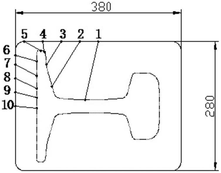
Figure 1 shows the cross-sectional schematic diagram of heavy rail. The up and down is the height direction of heavy rail, while the left and right is the width direction of heavy rail. The direction perpendicular to cross-section of heavy rail is the length direction. The corner radii R1 and R3 are equal to the R2 and R4 in value, respectively. Continuous casting slabs with the dimension of 7950 mm × 380 mm × 280 mm are adopted as billets (U71Mn) whose main chemical composition is C 0.71, Si 0.25, Mn 1.30, S 0.013, and P 0.019 in wt%.11–15 In the heavy rail rolling process, continuous casting slabs are charged into the furnace for reheating and then discharged at a temperature of 1240°C. In order to clear off the scale layer formed during the continuous casting and reheating periods, the billet at first passes through the scale cleaning unit that applies water with 220 bar pressure, then goes through the BD1 unit where the symmetric rolling is carried out, and box grooves are used, next through the BD2 unit where the asymmetric rolling is conducted, and grooves (calibers) of varying geometrical shapes are used, 16 and finally through the universal rolling unit which comprises of three stands, that is, universal roughing rolling mill (UR), edger roughing mill (ER)/edger finishing rolling mill (EF), and universal finishing rolling mill (UF).

Cross-sectional schematic diagram of heavy rail.
Figure 2 shows the schematic drawing of heavy rail rolling process. There are five passes in BD1, five passes in BD2, and six passes in universal unit. The grooves of BD1 unit are symmetric box grooves, while groove of each pass in BD2 and universal unit is the section groove. Figure 3 shows the roll distribution drawing of BD2 unit for 60 kg/m heavy rail. The schematic views of heavy rail rolling in universal rolling unit are given in Figure 4. Table 1 lists the rolling schedule table of 60 kg/m heavy rail.

Schematic drawing of heavy rail rolling process.

Roll distribution drawing of BD2 unit for 60 kg/m heavy rail.

Schematic views of heavy rail rolling in universal rolling unit: (a) UR1, UR2, and UR3; (b) ER; (c) EF; and (d) UF.
Rolling schedule table.

Experimental materials and procedures
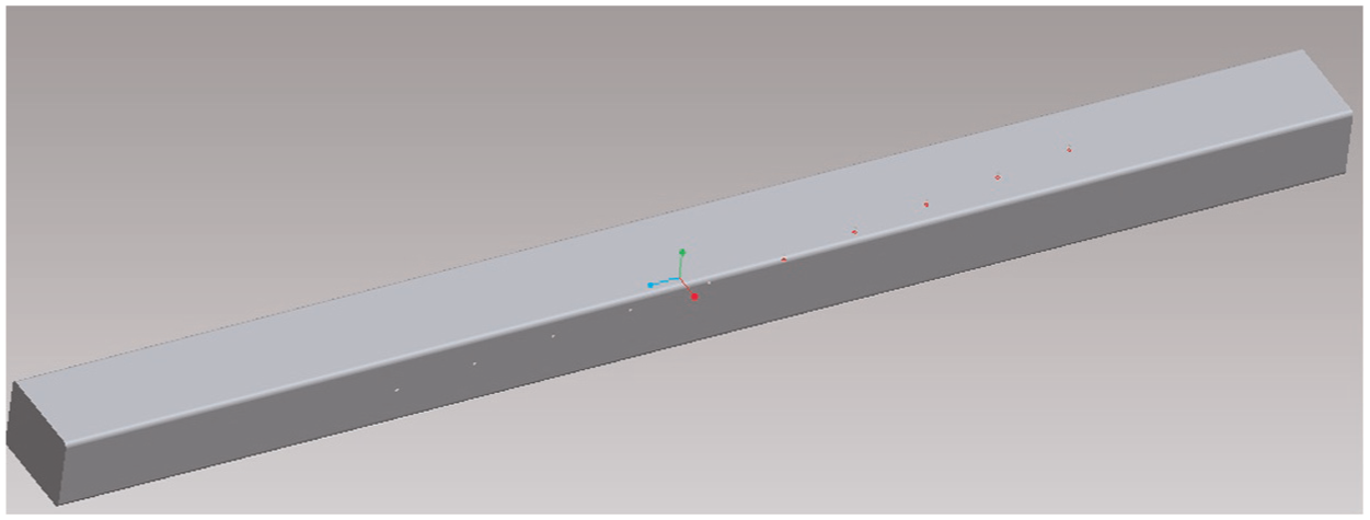
In order to trail the metal particle of rolled stock, artificial round holes with a dimension of φ12 mm × 20 mm were drilled in the trial billet which was the dimension of 5000 mm (length) × 280 mm (thickness) × 380 mm (width). The flow behavior of metal particle on the surface of rolled stock can be represented by artificial round hole because of the little dimension of round hole and large rolling reduction during the heavy rail rolling. Topography of round hole drilled in the trial billet is shown in Figure 5. Figures 6 and 7 show the wireframe and shade figures of the locations of round holes in the trial billet before numerical and physical simulation, respectively.

Topography of round hole drilled in the trial billet: (a) original photo and (b) magnification photo.

Wireframe figure of the locations of round holes drilled in the trial billet before rolling.
Shade figure of the locations of round holes drilled in the trial billet before rolling.
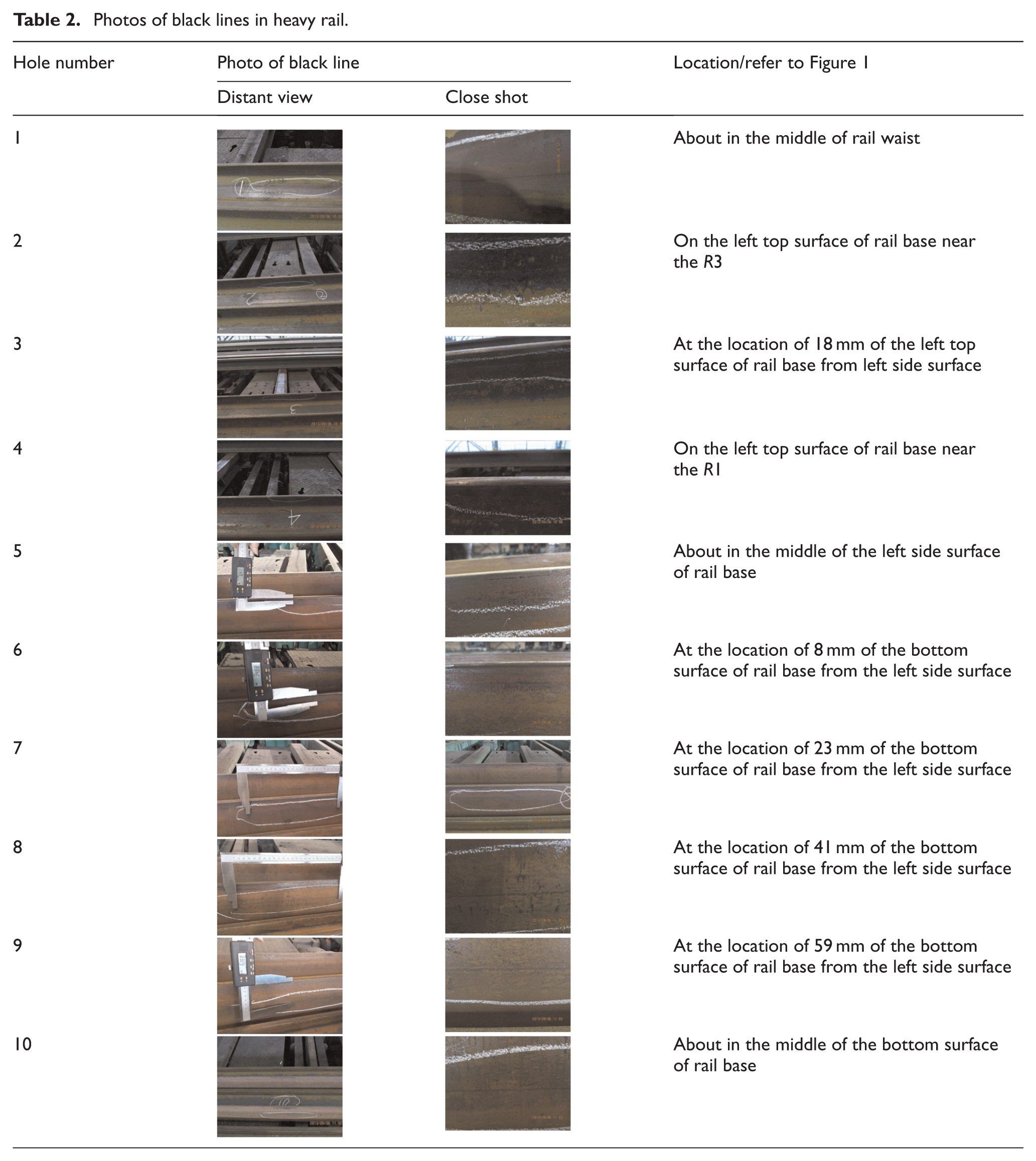
In this study, the artificial round holes changed into long black lines on the surface of heavy rail finished product after whole rolling. The locations of black lines were measured by ruler and human eyes. Table 2 shows the photos of black lines founded in the heavy rail final products after 16 passes rolling. The locations of round holes before and after rolling are shown in Figure 8. Due to large coefficient of elongation in the length or rolling direction, artificial round holes were elongated in the length direction after rolling and appeared in the form of long lines. At the same time, the surface of round holes was oxidized in the process of reheating in furnace, so a large number of round holes were very difficult to heal by rolling reduction due to hard and brittle oxide scale, and appeared in the form of black oxide scale.
Photos of black lines in heavy rail.
Locations of round holes before and after rolling.
Basic theory
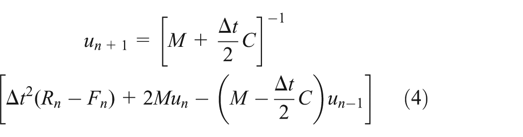
The basic equation of explicit dynamic analysis is

where M is the mass matrix, C is the damping matrix, F is the vector of inner force, R is the vector of outer loads,


The discrete-time recurrence equation can be determined by substituting equations (2) and (3) into equation (1)
In order to stably solve the central difference equation of 3D problem, the time step

where
Finite element model
Because the artificial round holes have very small size before rolling, in the meantime, it is the main objective of just tracking the locations of artificial round holes in the whole heavy rail rolling process. So, it is not necessary to make artificial round holes on the finite element model. In this simulation, continuous casting slab with a size of 5000 mm × 380 mm × 280 mm was adopted. The flow stress

where A, B, C, D are constant. A, B, C, and D are 5.103, 0.266, 0.116, and 4.464, respectively, according to thermal simulation test results of U71Mn using Gleeble-1500 thermal simulation experiment. The bilinear isotropic hardening material model (Figure 9) related to temperature was employed for the rolled stock. The strain rate

Bilinear isotropic hardening material model.

Physical parameters of U71Mn with temperature: (a) specific heat and (b) thermal conductivity.
Because the rolling line of 60 kg/m heavy rail was very long, and rolling passes were up to 16 passes, it was difficult to simulate it at a time. As a result, the simulation of the whole rolling process for 60 kg/m heavy rail was divided into 12 time cells as shown in Table 3. Due to symmetry of rolled stock and rolls in BD1 unit, only a quarter of rolled stock and rolls were employed in the geometric model, and the continuous rolling simulation model of BD1 unit was established at a time, as shown in Figure 11. No. 1 and No. 2 rolling passes were carried out in No. 1 groove of Figure 11, and other grooves were used only once. Rolled stock was tilted after No. 2, No. 3, and No. 4 rolling passes. Rolls and rolled stock were meshed with eight-noded hexahedral elements. After different mass scaling simulations, 100 times mass scaling with minor error was adopted. Reduction integration and hourglass control in the simulation setup were employed to save computational time and avoid the zero-energy mode caused by roll deformation, respectively. The hourglass energy is less than 10% of total internal energy. Figures 12 and 13 show the FE model of rolls of BD2 and universal unit, respectively. Figure 14 shows the FEM of rolled stock and rolls in UR1 groove rolling pass of universal unit. The Coulomb friction was adopted, and dynamic friction coefficient between rolls and rolled stock was set to 0.36. The effective coefficient of plastic converting into heat was set to 0.9. The initial temperature of continuous casting slab and rolls was set to 1180°C and a constant value of 200°C.
Simulation time cells of the whole rolling process for 60 kg/m heavy rail.


Geometric model of BD1 unit.

FEM of rolls in BD2 unit: (a) Groove E, (b) Groove D, (c) Groove C, (d) Groove B, and (e) Groove A.

FEM of rolls in universal unit: (a) UR1, UR2, and UR3; (b) ER; (c) EF; and (d) UF.

FEM of rolled stock and rolls in UR1 groove rolling pass of universal unit.
As shown in Table 3, the numerical simulation of the whole rolling process for 60 kg/m heavy rail was divided into 12 time cells, which included rolling period and cooling period. The simulation results of previous time cell, including temperature and structure results, were both as the initial condition of next time cell. Because work hardening and recrystallization were existed in hot rolling process at the same time, the effect of work hardening could be basically eliminated. Therefore, residual stress of previous time cell was not inherited by the next time cell in this article. A full size FE model of rolled stock of No. 2 time cell could be obtained by mapping the 1/4 FE model of rolled stock after No. 1 time cell along the plane of symmetry, as shown in Figure 15.

Finite element model of rolled stock after No. 1 time cell: (a) 1/4 model and (b) full size model.
Because initial mesh of rolled stock distorted seriously after multi-pass rolling simulation, calculation accuracy decreased directly and the FE model of rolled stock needed to rebuild at appropriate time. Yu et al.5,6 presented an updating geometric method for simulating V-H rolling process, but this method is only suitable for less rolling passes or small mesh distortion of rolled stock. It is necessary to mesh new gird for rolled stock when rolled stock go through a lot of rolling passes or mesh distortion. The model rebuilding method applied by Pei et al. 1 is not suitable for trailing metal particle during the whole rolling process for 60 kg/m heavy rail because the node positions have changed after remeshing. Figure 16 shows the flow chart of model rebuilding in this simulation, that is, extracting an element length body element from the finite element model of rolled stock after previous pass rolling in the middle position of the rolled stock length direction, then extracting nodes and lines on the surface of elements which perpendicular to the rolling direction, next generating the 2D surface meshes by connecting the existing lines, and finally, generating new 3D FEM of rolled stock by extruding surface meshes generated above along the rolling direction. After finishing model rebuilding, the temperature needed to be mapped from the old model to the new model according to the coordinates. After that, establishing the FE model of rolls for next pass, changing the material attribution of rolled stock, changing boundary conditions and loads, and then simulating the next pass rolling process, which make the rolling process simulation continuous. The following passes just as above.
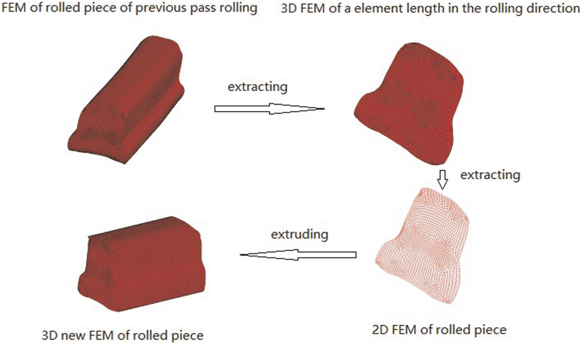
Flow chart of model rebuilding.
Results and discussion
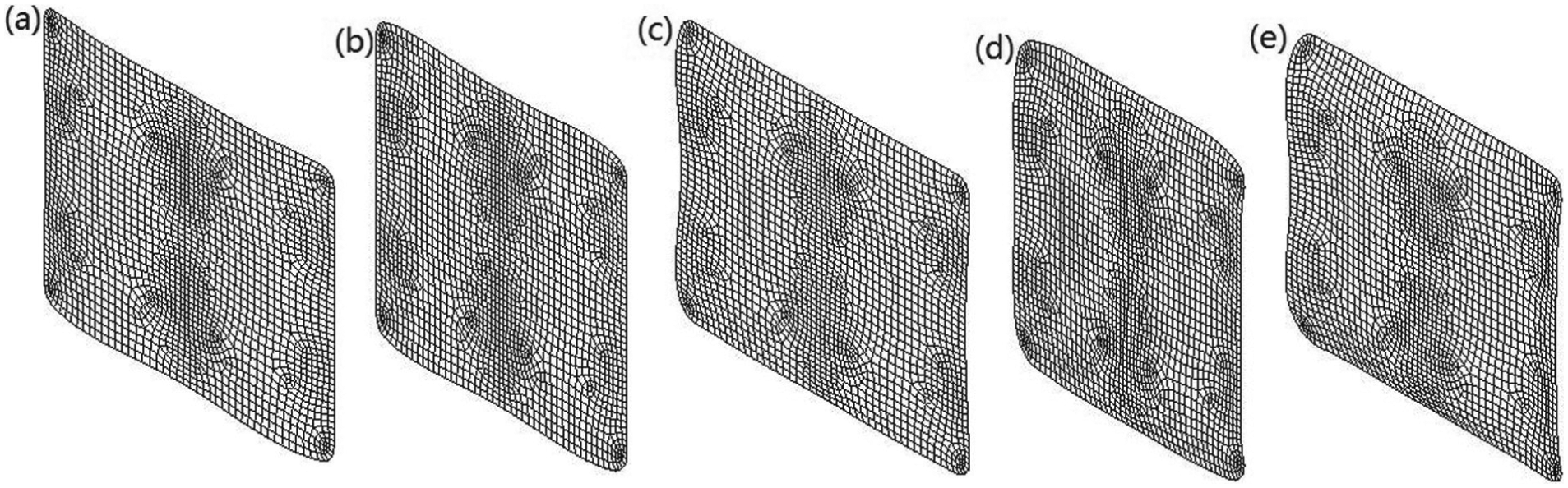
Figure 17 shows the groove filling simulation results of each pass in BD1 unit. From Figure 17, due to large section size of rolled stock, plastic deformation cannot penetrate into the center of rolled stock and then rolled stocks after No. 1–No. 5 rolling in BD1 unit appear double drum shapes. The roll gaps of No. 3 and No. 5 passes have not been filled well.

Groove filling results of (a) No. 1 pass, (b) No. 2 pass, (c) No. 3 pass, (d) No. 4 pass, and (e) No. 5 pass in BD1 unit.
Figure 18 shows the groove filling simulation results of each pass in BD2 unit. As shown in Figure 18, due to the smaller roll diameter on the left side of No. 6 pass groove, and the smaller metal flow resistance on the left side of groove than that on the right side, the metal from rolling reduction direction is easier to flow to the left side of groove, which leads to slightly not full on the right side of groove. The filling of No. 7 pass groove is good because of the symmetrical profile of groove. The groove profile of No. 8 pass has a big change, that is, there are the circular arcs with small curvature radii along the groove, so that the parts of the small arcs are not filled well. After No. 9 and No. 10 passes, the filling conditions are gradually improved, but the roll gap at the position of rail head after No. 10 pass rolling is still underfilled.

Groove filling results of (a) No. 6 pass, (b) No. 7 pass, (c) No. 8 pass, (d) No. 9 pass, and (e) No. 10 pass.
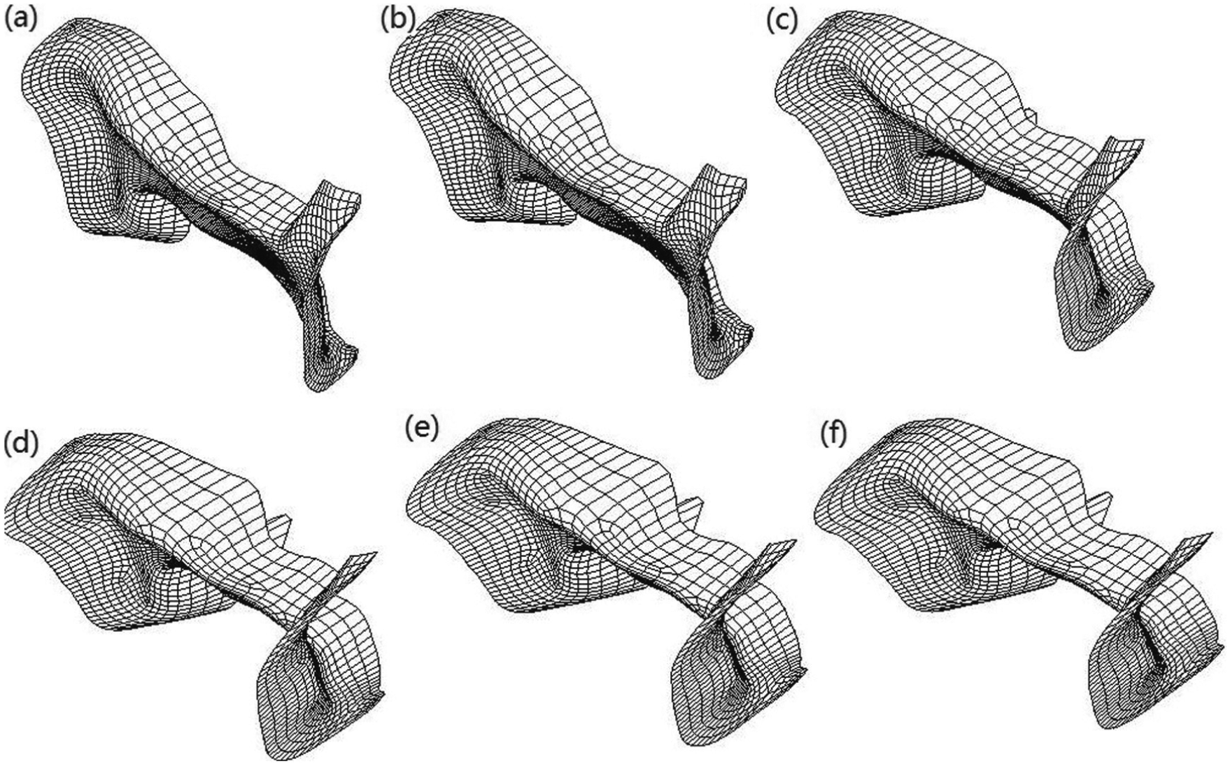
Figure 19 shows the groove filling simulation results of each pass in universal unit. From Figure 19, the main function of No. 12 and No. 15 passes is to control the width dimension of heavy rail, especially for the width of rail base and rail head, so the dimensional accuracy of the height of heavy rail is not important. The main mask of No. 11, No. 13, No. 14, and No. 16 passes is to adjust the width size of rail waist, the height size, and shape of heavy rail.

Groove filling results of (a) No. 11 pass, (b) No. 12 pass, (c) No. 13 pass, (d) No. 14 pass, (e) No. 15 pass, and (f) No. 16 pass.
In order to observe the metal particle flow of billet cross-section, isometric view of cross-section in the middle position of the billet length direction is shown in Figure 20. Figures 21–23 show 3D metal particle position results of each pass in BD1, BD2, and universal unit, respectively. From Figure 21, the positions of metal particles in BD1 unit are basically in a plane, and the cross-section of rolled stock is mainly rectangular. Because plastic deformation cannot go deep into the center of rolled stock, the flow velocities of metal particles on subsurface layer are faster than those in the center and on the surface, which leads to double drum shapes in the rolling direction.

Isometric view of cross-section in the middle position of billet length direction.
3D metal particle positions of (a) No. 1 pass, (b) No. 2 pass, (c) No. 3 pass, (d) No. 4 pass, and (e) No. 5 pass in BD1 unit.

3D metal particle positions of (a) No. 6 pass, (b) No. 7 pass, (c) No. 8 pass, (d) No. 9 pass, and (e) No. 10 pass.
3D metal particle positions of (a) No. 11 pass, (b) No. 12 pass, (c) No. 13 pass, (d) No. 14 pass, (e) No. 15 pass, and (f) No. 16 pass.
From Figure 22, the metal particle positions of rolled stock in BD2 unit are not hold in a plane and appear 3D status. Because of different rolling reductions along the roll length direction, rail waist has the biggest plastic strain, and rail base has the minimal plastic strain. Spatial features of metal particles in universal unit are more serious than those in BD2 unit, as shown in Figure 23.
In order to track the flow behavior of metal particles of rolled stock cross-section in the whole rolling process, some typical points of rolled stock cross-section are selected as shown in Figure 24. Points a, b, c, and d are located in the corner of cross-section of continuous casting slab; points e, f, g, and h are the midpoints of edges; and point i is the geometric center point.
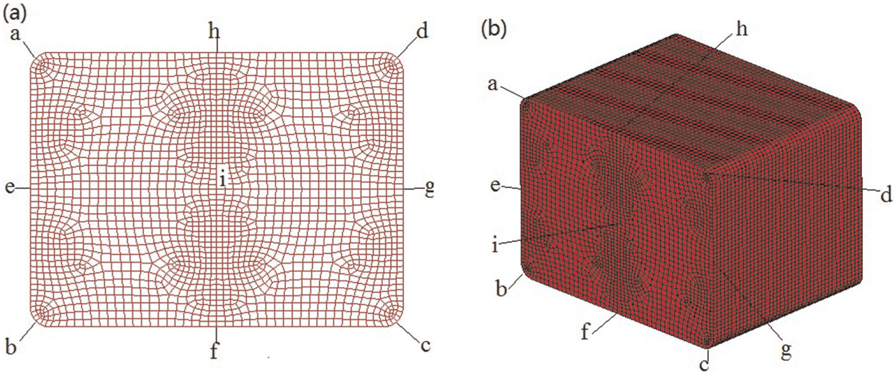
Position map of typical points: (a) plane and (b) spatial.
Figure 25 shows the positions of typical points of rolled stock cross-section in BD1 unit. From Figure 25, it is obvious that the positions of typical points of rolled stock cross-section have not changed basically on the relative position, just have changed on absolute position because of symmetrical box grooves in BD1 unit.

Positions of typical points of rolled stock cross-section after (a) No. 1 pass, (b) No. 2 pass, (c) No. 3 pass, (d) No. 4 pass, and (e) No. 5 pass rolling in BD1 unit.
Figure 26 shows the positions of typical points of rolled stock cross-section in BD2 unit. Points a and b are still in the corner of rolled stock because points a and b are on the side surface of rail base where little rolling reduction happens. Points c and d move to the side surface of rail head by turn over spread because of large amount of rolling reduction. Points e and g basically stay in the middle of edges of rolled stock cross-section due to basic horizontally symmetrical groove in BD2 unit. Points h and f move to the left of rolled stock height midpoint, that is, rail base of heavy rail because rolling reduction at points h and f is the largest, and the flow resistance of rail base is smaller than that of rail head. Point i is the same as the points h and f. At the same time, the grooves of No. 6, No. 8, and No. 9 are not completely horizontal symmetry, which lead to closer distance from rail base for point h than that for point f.
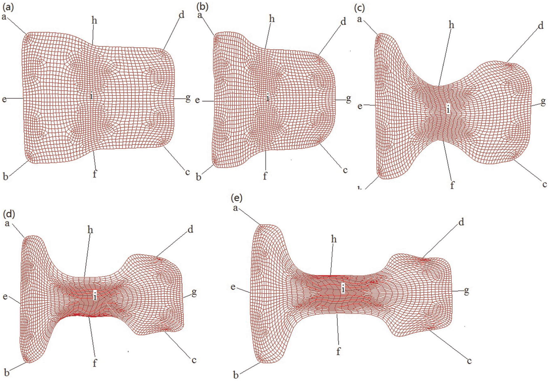
Positions of typical points of rolled stock cross-section after (a) No. 6 pass, (b) No. 7 pass, (c) No. 8 pass, (d) No. 9 pass, and (e) No. 10 pass rolling.
Figure 27 shows the positions of typical points of rolled stock cross-section in universal unit. From Figure 27, the horizontal distances between point h and point f become more and more big. At the same time, points c and d are getting closer and closer to border between side surface and bottom surface of rail head. Compared with BD2 unit, other points are almost not change.
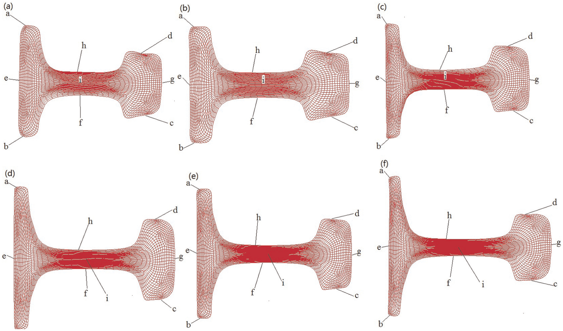
Positions of typical points of rolled stock cross-section after (a) No. 11 pass, (b) No. 12 pass, (c) No. 13 pass, (d) No. 14 pass, (e) No. 15 pass, and (f) No. 16 pass rolling.
Verification of experimental points
Figure 28 shows the positions of artificial round roles in FEM of continuous casting slab. The experimental points 540, 1064, 1069, 1074, 1079, 1085, 1090, 1095, 1100, and 1105 shown in Figure 28 are representative of artificial round holes 1, 2, 3, 4, 5, 6, 7, 8, 9, and 10 in experimental rolling, respectively.

Positions of artificial round holes in FEM of continuous casting slab.
Figures 29–31 show the positions of 10 experimental points of rolled stock cross-section in BD1, BD2, and universal unit, respectively. From Figures 29–31, we can track the positions of 10 experimental points in the whole heavy rail rolling and find out their flow rules.

Positions of 10 experimental points of rolled stock cross-section after (a) No. 1 pass, (b) No. 2 pass, (c) No. 3 pass, (d) No. 4 pass, and (e) No. 5 pass rolling in BD1 unit.

Positions of 10 experimental points of rolled stock cross-section after (a) No. 6 pass, (b) No. 7 pass, (c) No. 8 pass, (d) No. 9 pass, and (e) No. 10 pass rolling.
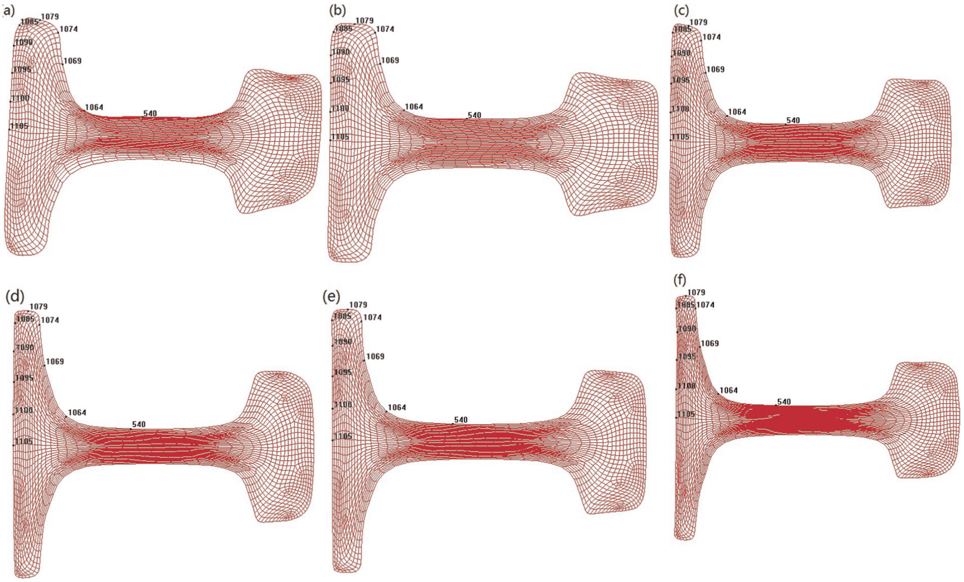
Positions of 10 experimental points of rolled stock cross-section after (a) No. 11 pass, (b) No. 12 pass, (c) No. 13 pass, (d) No. 14 pass, (e) No. 15 pass, and (f) No. 16 pass rolling.
Figure 32 shows the experimental and simulation results of the positions of 10 experimental points in the continuous casting slab and heavy rail final product. From Figure 32(a), the rectangle with rounded corners represents the cross-section of continuous casting slab. Points 1–10 on the side of the rectangle and heavy rail final product profile are on behalf of the positions of artificial round roles in the continuous casting slab and heavy rail final product. The simulation results are in good agreement with the experimental results by the naked eye.

Positions of experimental points in the heavy rail final product: (a) experimental results and (b) simulation results.
Figure 33 shows the experimental and simulation values of the positions of 10 experimental points in the heavy rail final product. From Figure 33, the simulation values are in good agreement with the experimental values. Because the metal at the rail base is free deformation in the width direction of heavy rail during the last pass rolling (No. 16 pass), the height error is smaller than the width error.

Experimental and simulation values of the positions of 10 experimental points in the heavy rail final product.
Conclusion
A 3D finite element model of whole heavy rail rolling for 60 kg/m heavy rail was built using explicit dynamic software and modified updating geometric method.
The groove filling of each pass in BD1, BD2, and universal unit was simulated. The groove filling of BD1 unit is good, and the cross-section of rolled stock is prone to double drum shape. The metal easily flows to position of small roll diameter in BD2 unit, and the position of large roll diameter and small arc has a slightly worse filling result. In universal rolling unit, grooves UR and UF fill well, and grooves ER and EF are underfilled in the height direction of heavy rail, especially for rail head part because grooves ER and EF mainly control the width of heavy rail rather than height.
3D metal particle positions of each pass in BD1, BD2, and universal unit were studied. The positions of metal particles of BD1 unit are basically in a plane, and the cross-section of rolled stock is mainly rectangular. In BD2 and universal unit, the positions of metal particles appear 3D status. Spatial features of metal particles of rail waist are the most serious, and the metal particles of rail base have the minimum plastic strain.
The flow rules of typical points of rolled stock cross-section in BD1, BD2, and universal unit were studied. The positions of typical points of rolled stock cross-section in BD1 unit have not changed basically on the relative position. In BD2 unit, points c and d move to the side surface of rail head by turn over spread, and points h, f, and i move to rail base. In universal unit, the horizontal distances between point h and point f become more and more big, and points c and d are getting closer and closer to border between side surface and bottom surface of rail head.
10 artificial round holes were drilled in the continuous casting slab. The simulation results of 10 experimental points are in good agreement with the experimental results of 10 artificial round holes in actual production line of Wuhan Iron and Steel (Group) Company, which means that the whole heavy rail rolling process can be analyzed by means of explicit dynamics FEM and modified updating geometric method.
Footnotes
Handling Editor: Kai Bao
Declaration of conflicting interests
The author(s) declared no potential conflicts of interest with respect to the research, authorship, and/or publication of this article.
Funding
The author(s) disclosed receipt of the following financial support for the research, authorship, and/or publication of this article: This work was financially supported by the National Natural Science Foundation of China (No. 51375353), Open Fund of the State Key Laboratory of Refractories and Metallurgy of WUST (No. 2014QN03), Open Fund of the Key Laboratory for Metallurgical Equipment and Control of Ministry of Education of WUST (No. 2013A17), and Wuhan Iron and Steel (Group) Company.