
Abstract
Multi-tip micro/nano-scratching technology has been widely used in precision manufacturing. In this study, the smooth particle hydrodynamic based on micro-scratching model is proposed to study the effect of double-tip inclined angles on such a scratching process. A series of simulations were conducted with the double-tip tilting with 0°, 5°, and 10° on the oxygen-free copper surfaces. In this article, the formation of burrs and scratching forces was illustrated and analyzed based on the simulation results. It is noted that when the double-tip tilted, the burrs generated more and side flows curled seriously during scratching process. With an increase in the scratching distance, more burrs generate on both sides of the groove. The tangential, thrust, and lateral forces are all affected by the extrusion of side flows and the protrusion in middle. Moreover, the scratching forces of tangential and thrust showed that the double-tip scratching process can be divided into three stages: initial scratching stage, transition scratching stage, and stable scratching stage. During transition scratching stage, the most violent scratching forces generated in the condition of the double-tip tilting with 10°.
Introduction
Oxygen-free copper (OFC) is an important material in many high-tech industrial applications because of its attractive property on deformability, conductivity, and machinability. It has been widely used in micro-electro-mechanical systems (MEMS), large-scale integration (LSI), and so on.1–4 Micro-scratch, as one of the most important ultra-precision measuring/manufacturing methods, obtained a great deal of achievements in the last decades for its outstanding capability on high precision of positioning, high surface finish quality, and intricate feature manufacturing. Therefore, it is of great importance to understand the machining mechanism and improve the scratched surface quality in micro-scratch of OFC.5–8
Nowadays, many researchers are focused on the improvement of the scratched surface quality. Certain types of scratch conditions, such as indenter shape, scratch feed, and residual stress, have significant effects on the micro-scratching process.9–12 Fang et al.13,14 studied the feed on the machining characterization of the nano-lithography process by experiment and molecular dynamics simulation. The conclusion is that the required surface could be obtained through changing scribing feed. Yan et al. 15 studied the effects of feed on the material removal mechanism of atomic force microscopy (AFM)-based nano-scratching process. They found that the adjacent grooves had a mutual effect on the smallest feed during continuous scratching process when the scratch feed decreased to a certain value and proposed the smallest feed of obtaining parallel grooves according to different scratching conditions. To overcome the feed limit of obtaining parallel grooves during scratching process, Zhang et al. 16 proposed a novel double-tip scratch method. It is proved that double-tip scratch could obtain parallel groove with high quality, which was not affected by scratch depth, feed, and crystallographic orientation. They also investigated the effects of tip tilt on the results of scratch by finite element analysis (FEA). 17
Contrary to the mentioned large number of papers, only a few focused on the formation of burrs and the effect on the scratched surface. The double-tip scratch not only improves the scratched groove quality but also produces a large amount of side flows due to the plowing effect. Curl of side flows and burrs can damage the scratched surface with a large extrusion. Therefore, it is very meaningful to study the influence of side flows on scratched surface.
In this article, scratch simulations of double-tip tilting with angles of 0°, 5°, and 10° were performed using smooth particle hydrodynamic (SPH) method with continuous media to understand the material removal process, and the influence of tilting angles of double-tip on scratch surface is studied. The change in tangential and thrust forces during the scratching process and the shape of the middle protrusion are discussed after the simulation.
SPH simulation
SPH method
SPH is a “truly” meshfree, particle method originally used for continuum scale applications, and may be regarded as the oldest modern meshfree particle method. The physical model produced in SPH method can be discretized with a cloud of nodes as shown in Figure 1. The node connectivity is defined by a circular domain called support domain, using the neighboring nodes as field value approximation according to equation. SPH particle approximations in a problem domain
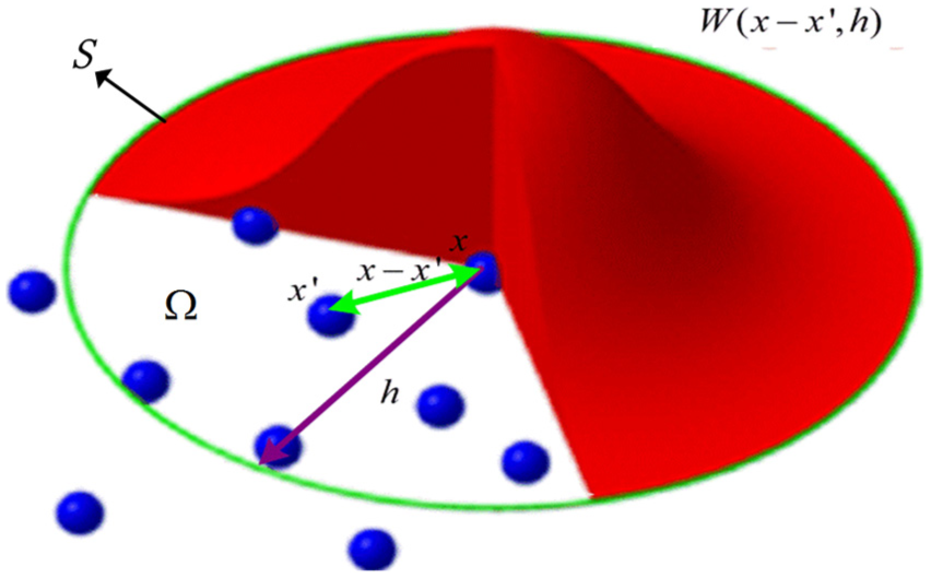
SPH particle approximations in a problem domain
Simulation model
The SPH double-tip scratch mode contains two parts as shown in Figure 2. The specimen is OFC which consists of 72,000 SPH particles, and the diamond tool is a cone with the angle of 30°. The deformation and wear of the tips could be ignored because the hardness of the OFC is different considerably from diamond. Therefore, the diamond tool is regarded as a rigid and unmeshed section in the simulation. The OFC specimen is homogeneous and isotropic. The size of the specimen is 4.0 µm × 6.0 µm × 3.0 µm in X, Y, and Z directions. The overall 6 degrees of freedom of specimen on the bottom and right side are fixed. The specimen’s front side and back side are fixed through defining two symmetry planes. Considering the accuracy of simulation, the diameter of the SPH particle is set to 100 nm.12,19

Micro-scratch model: (a) schematic diagram of double-tip scratch and (b) double-tip scratch model in LS-DYNA.
The two scratch tips in SPH model have the same configuration with the cone angle of 30° and the radius of the tip of 100 nm. The scratch models are implemented using SPH in the framework of LS-DYNA hydrodynamic software.
The double-tip scratch models under different inclined angles are shown in Figure 3. Three models of double tips tilting with 0°, 5°, and 10° in order to investigate the influences of inclined angle on the micro-scratching process. Specimen was rotated to Y direction to observe clearly. The double-tips scratch the surface simultaneously during the scratching process.

Schematic of double-tip scratch model with different inclined angles: (a) tilt 0°, (b) tilt 5°, and (c) tilt 10°.
The constitutive model of Johnson–Cook can describe the flow stress of the material by considering strain, strain rate, and temperature. 20 It is expressed as follows

More information of material parameters used in this article is shown in Table 1. 21
Material parameters of the oxygen-free copper.

Results and discussion
Scratched surface topography
The top and front views of the scratched surface with different inclined angles are shown in Figure 4. When the scratching distance is 4.0 μm, pile-up of chips forms a triangle region in the front of the double-tip because of high stress. As shown in Figure 4(a1)–(c1), the accumulation of both sides of the groove increases with the increase in the scratch length. The burrs in front of the double-tip accumulate during the scratching process and side flows become obvious. It is visible to see that the grooves left by the tips on the surface of specimens become wider as the tip tilts more.

Local top and front views of scratched surface after scratching with different inclined angles.
The profiles of the cross section are similar to the shape of double-tip, and there are significant pile-ups around the edge of specimens which can be observed from the front view of the scratch surface in Figure 4. With an increase in the inclined angle, the height of the middle protrusion increases, namely, h3 > h2 > h1. When the inclined angle is 0°, the middle protrusion is like a triangle with height of 0.45 μm. A deeper cutting depth is needed in the secondary machining process for this case. The middle protrusion changes to a trapezoid when the two tips incline at 5° and the height of the middle protrusion increases to 0.55 μm. Also when the inclined angle increases to 10°, the protrusion shape is close to a rectangle with the increased height of 0.90 μm. Meanwhile, the burrs of two sides curl seriously and are formed around the grooves on the surface of specimen as shown in Figure 4(a2)–(c2). The middle protrusion of specimen increases from 0.45 to 0.90 μm, and the shape changes when the double-tip tilts simultaneously. It is because the different stresses and gaps between the two diamond tips tilt different angles. The larger the angle, the larger gap between the two tips and larger stress on the surface, which makes side flows generated more.
Figure 5 shows the burrs formed during scratching process with different inclined angles. As we all known, the burrs compromise the surface integrity and go against the secondary machining during precise processes. When the scratching distance is 4.0 μm, from Figure 5(a1)–(c1), residual burrs on the surface of specimens look random in shape but also can observe burrs in Figure 5(c1). When the inclined angle is 0°, the middle protrusion is the least so that the deformation and removal mechanism of material is mainly due to side flows during scratching process. More burrs generated at the front of the tips when tilt with 5° and 10°. Middle protrusions and side flows, even chips all take part in the deformation and removal mechanism of material.

Section views of the residual surface during scratching process with different inclined angles.
The von Mises stress distribution should be presented in order to investigate the influence of the inclined angle on subsurface layer during double-tip scratching. The residual von Mises stress distributions with different inclined angles are shown in Figure 6. When the scratching distance is 4.0 μm, the plastic deformation exists in the subsurface layer of OFC and the deformation region presents a semicircular area around the tip during scratching process. The intensive deformation areas illustrated in Figure 6 vary from different inclined angles. It is clear to see the deformation area increased as the tilt angle becomes larger. It is due to the increase in extrusion of the tip on two sides of the surface as the double-tip tilts more. However, the depth of the area does not change according to a certain trend, and the depths of d1 and d3 are 1.47 μm and the depth of d2 is 1.19 μm approximately. In Figure 6, d1 = d3 > d2 is shown to indicate the depth of the deformation area.
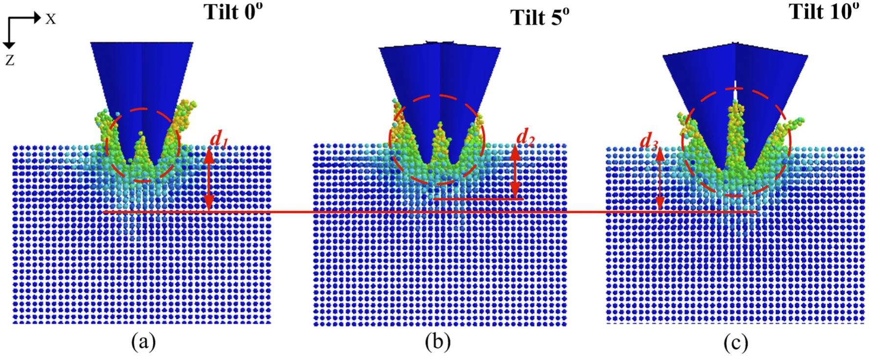
The residual von Mises stress distribution in the subsurface layer during scratching process with different inclined angles.
Scratching force
The tangential and thrust forces with different inclined angles during scratching process are shown in Figure 7. The scratching process can be divided into three stages according to the forces: initial scratching stage, transition scratching stage, and stable scratching stage. Tangential and thrust forces increase sharply in the initial scratching stage, and both of them present a linear relationship with scratching distance. The tips penetrate into specimen gradually and get to the depth settled during this stage. In transition scratching stage, tangential and thrust forces increase slowly but fluctuate greatly. In this period, larger inclined angle leads to larger forces. In the last stage, the inclined angles have little effect on the tangential and thrust forces.
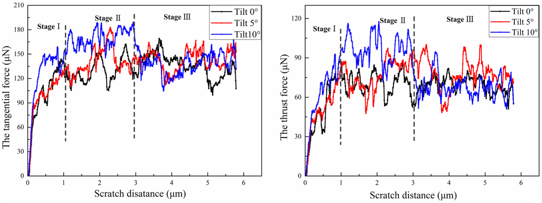
The tangential and thrust forces during scratching process with different inclined angles.
In Figure 7, these three stages are obvious in curves of tilt angles of 0° and 10° but not visible in the angle of 5°. It is due to the middle gap between the double-tips. The middle gap of the tilt angle of 10° is so large enough to form a high protrusion. Burrs generated by tips not only form side flows but also produce the middle protrusion. The gap of tilt angle of 0° is the minimum and the middle protrusion is the least. In this case, most of the burrs translate into side flows. But in the tilt angle of 5°, burrs, the middle protrusion, and side flows maintain a balanced relationship so that the transition stage and stable stage are almost the same. When tilt angle is 10°, tangential and thrust forces reach the maximum value. It is because the large angle increases the squeeze of the double-tip to the surface of the specimen. The instability is due to the generation of more burrs and chips accumulation in front of the double-tip. The third stage is more stable than previous relatively because of the burrs which transfer into middle protrusion and side flows become a stable state. We can find that the inclined angles have little effect on the tangential and thrust forces during this period.
The lateral forces exerted on the double-tip under different inclined angles are shown in Figure 8. The lateral force presents a linear increase within the scratch distance of 2 μm. This period is the process of accumulation of protrusion. The protrusion forms in middle and the side flows generate gradually. Subsequently, the lateral force fluctuates violently. The lateral force is affected by the extrusion of side flows and the protrusion in middle. The accumulation of both sides of the groove increases with an increase in the scratch length. That is to say, the increase in angle leads to more burrs, and more burrs make the force fluctuate more violently. As shown in Figure 8, it is clear to find out the amplitude of the variation of tilt angle of 10° is the maximum.

The lateral forces exerted on the double-tips during scratching process under different inclined angles.
Conclusion
Using the SPH method, the effect of double-tip inclined angles on the scratched surface topography, subsurface layer, and scratching force was investigated. The conclusions can be drawn as follow:
The height of middle protrusion increases and shape changes from triangular to rectangular with an increase in the inclined angle. Moreover, side flows curl seriously and burrs are generated when the inclined angle is 0° and 10°. And the burrs cause damage to the unscratched surface. Double-tips tilting a certain angle can restrain the generation of burrs, and it is beneficial to secondary machining.
During the process of double-tip scratch, the subsurface layer under double-tips undergoes plastic deformation and the shape presents semicircle. With an increase in the inclined angle, the semicircular area also increases, but the depth of plastic deformation area is the shallowest one under 5°.
With an increase in the scratching distance, more burrs generate on both sides of the groove. The tangential, thrust, and lateral forces are all affected by the extrusion of side flows and the protrusion in middle. The variation amplitude of tangential forces, thrust forces, and lateral forces is the maximum for the double-tip tilting of 10°.
Footnotes
Academic Editor: Pranab Samanta
Declaration of conflicting interests
The author(s) declared no potential conflicts of interest with respect to the research, authorship, and/or publication of this article.
Funding
The author(s) disclosed receipt of the following financial support for the research, authorship, and/or publication of this article: This work is funded by the National Natural Science Foundation of China (51422503 and 51505180), Jilin province science and technology development plan (20150203014GX, 20150520108JH and 20170101134JC), China Postdoctoral Science Foundation Funded Project (2015M580249 and 2017T100205), Special fund project of Jilin provincial industrial innovation (2016C030) and Fundamental Research Funds for the Central Universities.