
Abstract
A contra-rotating axial-flow fan is prone to stalling and motor overload at partial flow rates. Moreover, its efficiency decreases sharply at a high flow rate, which is accompanied by disparity between the shaft powers of the two impellers and the light loads of their motors. It is necessary to maintain a high fan operating efficiency and a reasonable match between the powers of the two impellers. In this study, model and simulation analyses of a mine contra-rotating axial-flow fan were conducted. Different impeller rotational speeds were obtained by controlling the pole speed. The aerodynamic characteristics, namely, the total pressure rise, shaft power, and operating efficiency, were investigated with respect to the flow rate and rotational speed combination of the impellers. The pressure and velocity distributions were also determined and analyzed. The high-efficiency operating range and variation range of the total pressure rise of the fan with different speed combinations were obtained. The findings indicate that the variable speed operation of two impellers can expand the fans’ stable operating range and that impeller speed combinations can be set based on the flow rate and the resistance of the pipe network. This enables the contra-rotating axial-flow fan to operate in the high-efficiency operating range.
Keywords
Introduction
Contra-rotating axial-flow fans (CRAFFs) are used for diverse purposes such as ventilation during mining and tunnel construction. This is because of their many favorable features, which include compactness, low noise, high pressure generation, high flow rate, and high efficiency.
When a CRAFF is connected to a ventilation pipe, the operating point is the intersection of the aerodynamic performance curve of the fan and the resistance curve of the pipe network. The flow rate at the operating point decreases with increase in the resistance of the ventilation pipe network. In the early operation stage, the resistance of the ventilation pipe network is small, and the flow rate at the operating point is thus higher than the design flow rate of the CRAFF, resulting in a sharp decrease in the total efficiency of the CRAFF and mismatch between the shaft powers of the front and rear impellers. However, in the later operation stage, the resistance of the ventilation pipe network becomes large, and the flow rate at the operating point decreases to below the design flow rate of the CRAFF. Further decrease in the flow rate may cause the CRAFF to stall or surge.
By adjusting one of the two curves, the CRAFF may be made to operate with a high efficiency under off-design conditions. 1 The curve of the total pressure rise against the flow rate of the fan can be adjusted by varying the blade installation angle, or the rotational speed of the impellers. When the rotational speed of the CRAFF is constant, the inlet flow angle of the air is consistent with the inlet geometry angle of the aero foil, namely, the angle of incidence. Under this condition, the angle between the chord line and the mean relative velocity vector is nearly zero. The angle of incidence increases with the decrease in the flow rate, because the inlet axial velocity decreases with decreasing flow rate while the circumferential velocity remains constant. When the angle of incidence reaches a critical value, flow separation occurs near the suction side of the blade, and the total pressure rise of the fan decreases rapidly. If the setting angle of the blade can be varied to adapt it to the changing flow, the fan would be able to operate stably under low flow rate conditions. Such would require the incorporation of an adjusting device, although the setting angle of the blade of some fans cannot be adjusted. Jiabin and Haibo 2 investigated the problem of the significant decrease in the flow rate of a CRAFF when used in a long-distance network and of the considerable difference between the powers of the two impellers under excessive flow rate conditions. Their work verified the feasibility of improving the aerodynamic performance of a CRAFF by changing the setting angle of the blade. However, an abnormal adjustment of the setting angle of the moving blade under variable working conditions may cause abnormal vibration and noise generation by the fan, 3 which could result in shutdown or significant deterioration of the aerodynamic performance of the axial-flow fan.4,5
Conversely, by decreasing the rotational speed of the fan when the flow rate decreases, the inflow and outflow velocity triangle of the impeller under a variable working condition can be made similar to that for the design condition. Thus, the angle of incidence under a variable working condition is almost the same as that for the design condition. Hence, by decreasing the rotational speed of the fan when the flow rate decreases, the fan can be adapted to the change in the flow and made to operate stably under a low flow rate condition. This method is convenient because it does not require any change in the structure of the fan. Sharma et al. 6 and Pundhir and Sharma 7 experimentally investigated the effects of the rotational speed of the two impellers on the aerodynamic performance of a CRAFF. Xizhi et al. 8 and Qiushi et al. 9 also theoretically and experimentally analyzed existing methods and approaches to expanding the stable operating range of a CRAFF. Chen et al. 10 significantly improved the operation efficiency of a contra-rotating axial compressor by changing the rotational speed of the two impellers. Mistry and Pradeep 11 examined the effects of varying the axial spacing and rotor speed combination on the performance of a high-aspect-ratio contra-rotating axial fan. However, the details of the internal flow field of a CRAFF under differing speeds of the two impellers remain unclear. Recently, Zijian et al. 12 proposed a method for achieving even distributions of the total pressure rise and shaft powers of the two impellers without changing the total pressure rise characteristic curve of the CRAFF. However, the method’s utilization of frequency converters increases the complexity of the control system of the CRAFF. Moreover, it makes the satisfaction of the requirements for explosion prevention in underground tunnels more difficult.
In this study, the simulation model of a CRAFF used for mine ventilation was established and verified by comparing its predictions with experimental results. The simulation model was used to examine the aerodynamic performance of the CRAFF with respect to the speed combination of the two impellers. The total pressure rise and shaft powers of the two impellers and the efficiency of the fan with respect to the flow rate and impeller speed combination were also calculated. In addition, the variation ranges of the flow rate and shaft powers of the two impellers for the achievement of a high efficiency of the fan were estimated. Finally, the appropriate speed combination of the two impellers with respect to the flow rate and resistance of the ventilation pipe network was established. This study aims to present a rule to select the proper speed combination of the two impellers according to the flow rate and the resistance of the ventilation pipe network to promise to enable high-efficiency operation of CRAFFs under off-design conditions.
Prototype fan model and test rig
Prototype fan model
This study considered a CRAFF used for mine ventilation, namely, an FBDCZ No. 14/2*45. The fan is mainly composed of an air collector, a front duct, a front impeller, a rear impeller, a rear duct, a diffuser, and a muffler and can be easily installed and operated. The rated flow rate of the fan is 24.43 m3/s, the operating total pressure rise range is 165–1050 Pa, the impeller diameter is 1400 mm, and the hub-tip ratio is 0.61. The fan is housed in a 1404 mm diameter casing. The front and rear impellers have 13 and 11 blades, respectively, and a rated rotational speed of 980 rev/min. Each impeller is directly driven by an explosion-proof three-phase asynchronous motor. The twist angle between the root and top of the front impeller blade is 19.3°, while that of the rear impeller blade is 9.2°. The distance between the two impellers is 48 mm, and both have hubs of width 195 mm. The air collector has an inlet diameter of 1820 mm, while the outlet of the diffuser has a diameter of 1920 mm. The total length of the CRAFF is 7190 mm.
The models of the two impellers were built in SolidWorks 2012 (x64 edition) and imported into Gambit 2.4.6. The models of the other parts of the CRAFF were built in Gambit 2.4.6. The complete model of the CRAFF is shown in Figure 1.

Model of the CRAFF.
The flow domain of the CRAFF model in Figure 1 was discretized in Gambit 2.4.6. At the beginning, we tried to discretize it using unstructured grids without considering the influence of tip clearance. The results of simulations using 2,231,539, 4,087,570, and 7,034,008 volume cells were compared, and the residual error was determined to be less than 10−4. The results, which are shown in Figure 2, revealed low calculation accuracies when using 2,231,539 and 4,087,570 volume cells and that the flow characteristics of the models with 7,034,008 volume cells are more consistent with those of the test fan. However, there exists significant deviation at off-design operating conditions. The model with 2-mm tip clearance was thus adopted for the simulations of this study. The tip clearance of the front and rear impeller contained 582,637 and 481,214 volume cells, respectively. The front and rear impeller regions contained 2,777,128 and 2,747,532 volume cells, respectively. Fine volume cells were employed near the boundaries. The y+ was less than 5 near the hub and the cases of the front and rear impellers. The number of the volume cells of the model is 14,596,359. The resulting meshing scheme of the computational domain is shown in Figure 3. Volume cells near boundary layers were automatically adapted according to y+ in ANSYS FLUENT 15.0. The result, which is shown in Figure 2, revealed that the flow characteristic of the model with 2 mm tip clearance is perfectly consistent with that of the test.
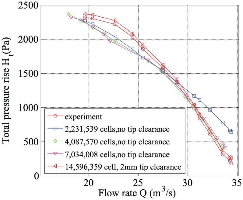
Results of total pressure rise versus flow rate under different volume cells.

Meshing scheme of the CRAFF: (a) casing, (b) details of in-wall, (c) details of nose fairing, (d) details of blades and hubs, (e) details of tail fairing, (f) details of tip clearance of front impeller, and (g) details of tip clearance of rear impeller.
It was assumed that the internal fluid was incompressible; and heat transfer and the gravitational effects were neglected. The Reynolds number (Re) of the air in a CRAFF is usually large (>2300), with the flow becoming turbulent. Furthermore, swirling flow occurs around the front and rear impellers. Consequently, the re-normalization group (RNG) two-equation k–ε turbulence model 13 was adopted for the steady flow numerical calculations. The RNG model was developed using RNG methods by Yakhot and Orszag 13 to renormalize the Navier–Stokes equations, to account for the effects of smaller scales of motion. It can offer improved accuracy in rotating flows.
For solving steady flow filed in turbo machinery, FLUENT has two kinds of processing methods, which are rotating reference frame (RRF) and multiple reference frame (MRF) models. RRF is only applicable to the flow field of turbo machinery without considering the influence of the stator, in which the RRF is fixed on the rotor and moves with the rotor. Since the rotational boundary is moving at the same speed as the coordinate system is, the rotational boundary is stationary with respect to the coordinate system, and the unsteady flow calculation is converted into steady flow one, in which the influence of inertia force is considered. MRF model considers the influence of stator to the flow field which is divided into several flow regions in different rotational speeds, and each region is calculated in its RRF; the flow velocity is forced to be continuous at the interfaces between the rotating fluid and the adjacent regions.
There are two impellers in the CRAFFs, so it is necessary to use MRF to deal with the regions of the rotating fluid around the two impellers. 14 Wall boundary conditions were applied to the surfaces of the fans in their respective reference frames, with a standard wall function utilized near the wall. 15 Boundary conditions of pressure-inlet and pressure-outlet were, respectively, applied to the inlet and the outlet of CRAFF. The outlet pressure was set to 101,325 Pa, which is the standard atmospheric pressure.
The commercial software ANSYS FLUENT™ 15.0 was used for the numerical analysis. The SIMPLE algorithm was used in conjunction with the RNG k–ε turbulence model to solve the three-dimensional Navier–Stokes equations in implicit formulation.16,17 The equations were discretized using a second-order upwind scheme, with the residual errors controlled to below 10−4. For each flow rate condition, convergence was achieved after approximately 12,000 iterations. The computations were performed on a Lenovo™ computer with two Genuine Intel® CPUs frequency of 2.20 GHz and 32.0 G random-access memory (RAM) memory.
The cross-sectional positions of the inlets and outlets of the front and rear impellers in the model are indicated in Figure 1. These points also coincide with the interfaces between the regions of the impellers and the adjacent regions. The total pressure rise in the CRAFF, Ht, is defined as the total pressure difference between its inlet and outlet. The increase in total pressure rise across the front and rear impellers, H1t and H2t, respectively, is similarly defined. To eliminate the effect of the reversed flow across the monitoring surface, the mass-weighted average total pressure rise at the monitoring surface was measured.
The impeller shaft torque is given by

where T is the impeller shaft torque; S denotes the impeller surface, which includes the pressure surfaces, suction surfaces, and tip surfaces of the blades, as well as the hub surface of the impeller;
The shaft power of the impeller can be expressed as

where Ps is the shaft power of the impeller, ω is the angular velocity of the impeller, n is the rotational speed of the impeller, and P1s and P2s denote the shaft powers of the front and rear impellers, respectively.
The total efficiency of the CRAFF is thus given by

where η is the total efficiency and Q is the flow rate. The total efficiencies of the front and rear impellers, η1 and η2, respectively, are similarly defined.
Figure 4 shows the performance curves of the CRAFF, namely, the curves of the total pressure rise and total efficiency as functions of the flow rate, at 980 rev/min. As can be seen from Figure 4, the simulation and experimental results are in good agreement. The maximum and average deviations between the two results within the simulation range are 4.61% and 3.44%, respectively, and only 5.26% under the design condition. This shows that the model and employed number of grids enabled accurate computation of the performance of the CRAFF. The numerical simulation was thus reliable. The CRAFF was found to have a high total efficiency under the design condition, with the efficiency decreasing rapidly under off-design conditions. This is primarily because the total efficiencies of the two impellers decrease significantly under partial flow rate conditions and that of the rear impeller also decreases sharply under high flow rate conditions, as can be seen from Figure 5(c).

Performance curves of the CRAFF at 980 rev/min: (a) total pressure rise and (b) total efficiency versus flow rate.

(a) Total pressure rise, (b) shaft power, and (c) total efficiencies of the two impellers versus flow rate at 980 rev/min.
Figure 5 shows the curves of the total pressure rise, shaft power, and total efficiencies of the two impellers as functions of the flow rate at 980 rev/min. As can be seen, the total pressure rise and shaft power of the rear impeller increase more rapidly with decrease in the flow rate compared to those of the front impeller and vice versa. These results indicate that the driving motor of the rear impeller is probably overloaded under partial flow rate conditions and small/no-load conditions at high flow rates. In addition, the total efficiency of the front impeller is high within the stable flow rate range, but that of the rear impeller decreases sharply under high flow rate conditions.
Figure 6 shows the absolute flow velocity distributions along the blade height at the inlets and outlets of the two impellers and the CRAFF for flow rates of 19.6117, 24.4300, and 31.1675 m3/s, which are representative of a partial flow rate, the design flow rate, and a high flow rate, respectively. Figure 6(a) shows the axial-flow velocity distributions at the inlet and outlet of the front impeller. It can be seen that the velocity distributions are basically uniform for the design and high flow rates, except in the regions near the blade tip and the hub. However, the axial velocity near the blade tip is apparently lower than that near the hub for partial flow rate. Figure 6(b) shows the axial-flow velocity distributions at the inlet and outlet of the rear impeller. It can be seen that the velocity distributions are also basically uniform under the design and high flow rate conditions, except in the regions near the blade tip and the hub. However, the axial-flow velocity near the blade tip at the outlet of the rear impeller is apparently higher than that near the hub for partial flow rate. Figure 6(c) shows the axial-flow velocity distributions at the inlet and outlet of the CRAFF. It can be seen that the axial velocity distributions are almost uniform, except that the axial velocity at the outlet increases with increase in the radius for partial flow rate. Figure 6(d) shows the tangential flow velocity distributions at the inlet and outlet of the front impeller. As can be seen, there is almost no tangential velocity at the inlet of the front impeller. This is consistent with the assumption regarding the condition at the inlet of this impeller. However, the tangential flow velocity at the outlet of the impeller increases rapidly due to the work done by the impeller. The distribution curve progresses in a downward left direction with increase in the flow rate. Figure 6(e) shows the tangential flow velocity distributions at the inlet and outlet of the rear impeller. It can be seen that the tangential flow velocity distribution at the inlet of this impeller is similar to that at the outlet of the front impeller. This is because the surface of the rear impeller inlet is very close to that of the front impeller outlet. Figure 6(f) shows the tangential flow velocity distributions at the inlet and outlet of the CRAFF. It can be seen that the tangential velocity at the inlet is almost zero, agreeing with the assumption regarding the inlet condition. The tangential velocity distributions at the outlet are almost zero for the design and high flow rates. However, the absolute tangential velocity at the outlet is not uniform and increases with increase in the radius for the partial flow rate.

Absolute flow velocity distributions at the inlets and outlets of the two impellers and the CRAFF for the design speed combination: (a) axial velocities at the inlet and outlet of the front impeller, (b) axial velocities at the inlet and outlet of the rear impeller, (c) axial velocities at the inlet and outlet of the CRAFF, (d) tangential velocities at the inlet and outlet of the front impeller, (e) tangential velocities at the inlet and outlet of the rear impeller, and (f) tangential velocities at the inlet and outlet of the CRAFF.
Test rig
To verify the numerical simulation results, a test rig of the CRAFF was set up based on the national standard for the aerodynamic performance testing of fans in China, 18 as shown in Figure 7. The rotational speeds of the motors were controlled by two frequency converters.

Test rig of CRAFF.
The rotational speeds of the motors were measured by a digital tachometer (DSS-2A), with an error of ±1 rev/min. The output power of the motors was measured by the electrometric method using the following corresponding calculation formula

where P1 is the input power of the motor, U is the root mean square (RMS) of the line voltage, I is the RMS of the line current, cosφ is the power factor, and η is the efficiency of the motor, as determined from the efficiency versus RMS of line current curve. A three-phase power quality analyzer, Fluke 434-II, was used to measure the input powers of the motors. During the test, it was ensured that the RMS of the line voltage was within 380%±6% V. The relative deviations of the measured powers were within 1%.
The flow rate was uniformly and gradually decreased by the metal-mesh throttle, and the total pressure rise was measured using a five-hole pitot tube. The measurement points were located in the planes of the inlet and outlet of the CRAFF, as shown in Figure 1. A total of 20 measurement points were set in the radial direction of the impellers in each plane, and the radial distributions of the total pressure rise and the loss of total pressure rise were determined. The flow rate was measured using an imported collector. The corresponding calculation formula is as follows 19

where
The performance of the CRAFF was measured for different flow rates between the near-stall flow rate (19.6117 m3/s) and the maximum flow rate (34.3836 m3/s). Adequate time was needed for stabilization of the pressure, flow rate, and temperature before their measurement. The pressure gauges, thermometers, and other instruments used in the test had been previously calibrated. The performance parameters of the CRAFF under the temperature and humidity conditions of the laboratory were converted to those for standard conditions, namely, 101.325 kPa, 20°C, and 50% relative humidity.
Results and discussions
Eight different combinations of the rotational speeds of the front and rear impellers were used for the numerical simulation of the differential speed operation of the CRAFF. The combinations are enumerated in Table 1. The performance of a CRAFF has been determined to be poor when the ratio of the rotational speed of the rear impeller to that of the front impeller is <0.6. 20 Consequently, the speed combination of 980−490 rev/min was not included in the present numerical simulations of the CRAFF.
Different speed combinations of the two impellers.

Static characteristics
Figure 8 shows the performance curves of the CRAFF with respect to the flow rate and speed combination of the impellers. It can be seen that there exists similar lowest flow rate when the rotational speed of the front impeller is the same (in some cases, not the same) and that the total pressure rise increases with the increase in the rotational speed of the rear impeller. This indicates that the rotational speed of the front impeller has great effect on the lowest flow rate and that of the rear impeller has great effect on the total pressure rise of the CRAFF. Furthermore, for a given flow rate, the total pressure rise for a speed combination of 980–740 rev/min is higher than that that for 740–980 rev/min, and the total pressure rise for 740–490 rev/min is higher than that for 490–740 rev/min. The flow rate for the highest efficiency increases with the speed combination in the following order, from the lowest to the highest: 490–490, 490–740, 740–490, 740–740, 740–980, 980–740, and 980–980 rev/min. In addition, the high-efficiency operating range of the fan, namely, where the efficiency is higher than 0.9 the maximum efficiency, widens with the speed combination in the same order. However, there is no significant change in the maximum efficiency with changing speed combination.
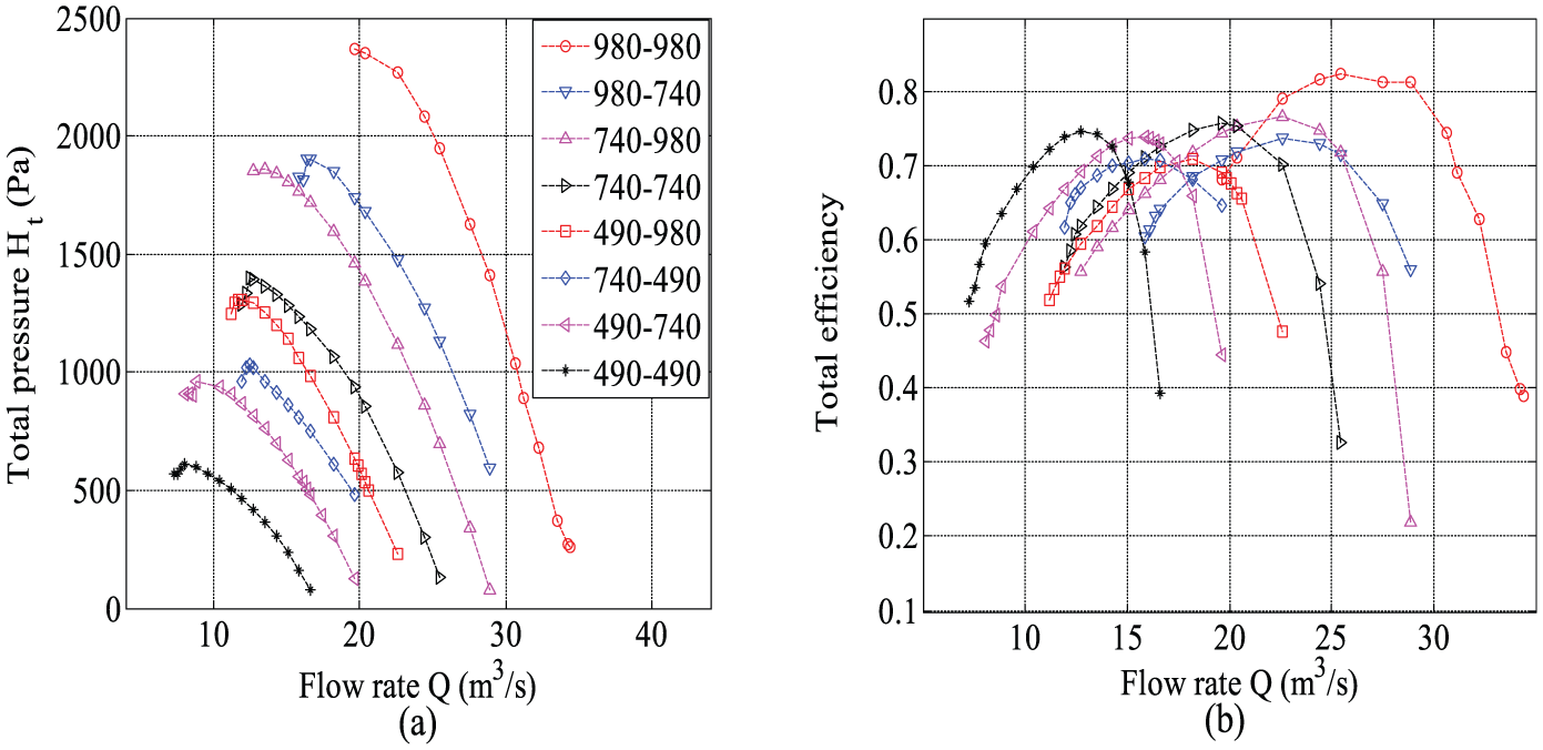
Performance curves of the CRAFF with respect to the flow rate and impeller speed combination: (a) total pressure rise and (b) total efficiency.
Total pressure rise and shaft power
Figure 9 shows the total pressure rise and shaft power curves of the two impellers with respect to the flow rate and speed combination of the impellers. It can be seen that for a given rotational speed of the front impeller, the variations in the total pressure rise and shaft power of the front impeller with respect to the flow rate are almost the same. The reason is the rear impeller has no influence on the inlet of the front impeller and little influence on the outlet of the front impeller. However, the curves of the total pressure rise and shaft power of the rear impeller shift toward the upper right with increase in the rotational speed of the rear impeller for a given flow rate. Furthermore, when the rotational speed of the rear impeller is maintained constant, the curves of the total pressure rise and shaft powers of the two impellers shift toward the upper right with increase in the rotational speed of the front impeller for a given flow rate. These observations indicate that the rotational speed of the front impeller determines the flow rate of the CRAFF and that the total pressure rise increases with increase in the rotational speed of the two impellers. The flow rates of the CRAFF that produce the highest efficiency for different impeller speed combinations are given in Table 2.

(a) Total pressure rise and (b) impeller shaft power with respect to the flow rate and impeller speed combination.
Flow rate of the CRAFF for highest efficiency with respect to the impeller speed combination.

CRAFF: contra-rotating axial-flow fan.
Figure 10 shows the distributions of the total pressure rise in the axial direction when the CRAFF is operated with the maximum efficiency for a given impeller speed combination. The left and right sides of the graphs correspond to the inlet and outlet of the CRAFF, respectively. There is a drop in total pressure rise when the air flows through the collector region due to the friction of the case and nose fairing. However, the total pressure rise increases when the air flows through the region of the front impeller because of the work done by the front impeller. This is followed by a small pressure drop, after which the total pressure rise increases again when the air flows through the region of the rear impeller because of the work done by the rear impeller. Finally, the total pressure rise slightly decreases when the air flows through the region of the diffuser, due to the friction and the mixing in the diffuser.

Distributions of the (a) total pressure rise of the CRAFF and (b) total pressure rise of the two impellers in the axial direction at maximum efficiency with respect to the impeller speed combination.
Figure 11 shows the distributions of the total circumferentially averaged pressures in the radial direction at the inlet and outlet of the two impellers and the CRAFF during operation at the maximum efficiency with respect to the impeller speed combination. As can be seen from Figure 11, the distributions at the inlet of the front impeller and the CRAFF are nearly uniform (Figure 11(a) and (c)), whereas the total circumferentially averaged pressure at the inlet of rear impeller increases with increase in the radius (Figure 11(e)). The bow distribution at the inlet of the front impeller is mainly due to the resistance of the nose fairing. The total circumferentially averaged pressures at the outlet of the two impellers increase in the radial direction. However, the distribution at the outlet of the CRAFF is nearly uniform.

Distributions of the total circumferentially averaged pressures in the radial direction at the (a) inlet of the CRAFF, (b) outlet of the CRAFF, (c) inlet of the front impeller, (d) outlet of the front impeller, (e) inlet of the rear impeller, and (f) outlet of the rear impeller during operation with the maximum efficiency with respect to the impeller speed combination.
Flow velocity
Figure 12 shows the distributions of the circumferentially averaged axial-flow velocities at the inlets and outlets of the two impellers (along the blade height) and the CRAFF during operation at the maximum efficiency with respect to the speed combination of the impellers. Figure 12(a) shows the distributions for the front impeller, from which it can be seen that the distributions at the inlet are almost uniform, except in the regions near the blade tip and the hub, and that the circumferentially averaged axial-flow velocities at the outlet decrease with increase in the radius. When the radius is larger than half of the blade height, the axial velocity at the outlet is lower than that at the inlet, and when the radius is smaller than half of the blade height, the axial velocity at the outlet is higher than that at the inlet. Figure 12(b) shows the distributions for the rear impeller, and it can be seen that they are better than those in Figure 12(a). Figure 12(c) shows the distributions for the CRAFF, from which it can be observed that the distribution at the inlet is nearly uniform for every flow rate and that the distribution at the outlet of the CRAFF is almost uniform, except in the regions near the blade tip and the hub. Figure 12(d) shows the tangential flow velocity distributions at the inlet and outlet of the front impeller. It can be seen that the tangential velocity is very low but positive at the inlet, agreeing with the assumption of a uniform distribution of the inlet velocity, whereas the tangential velocity at the outlet increases with increase in the radius. Furthermore, for a given rotational speed of the front impeller, the distribution curves of the tangential velocities shift toward the left with increase in the rotational speed of the rear impeller. Figure 12(e) shows the tangential flow velocity distributions at the inlet and outlet of the rear impeller. It can be seen that the distribution at the inlet of the rear impeller is very similar to that at the outlet of the front impeller. This is because of the closeness of the inlet surface of the rear impeller to the outlet surface of the front impeller. The absolute tangential velocities at the inlet and outlet of the rear impeller increase with increase in the radius. In addition, when the difference in the rotational speeds of the two impellers is the same or comparable, the tangential velocity distribution at the outlet of the rear impeller is also the same or similar to each other. Figure 12(f) shows the tangential flow velocity distributions at the inlet and outlet of the CRAFF. It can be seen that the tangential velocities at the inlet and outlet of the CRAFF are almost zero, which is conducive to the efficient operation of CRAFF
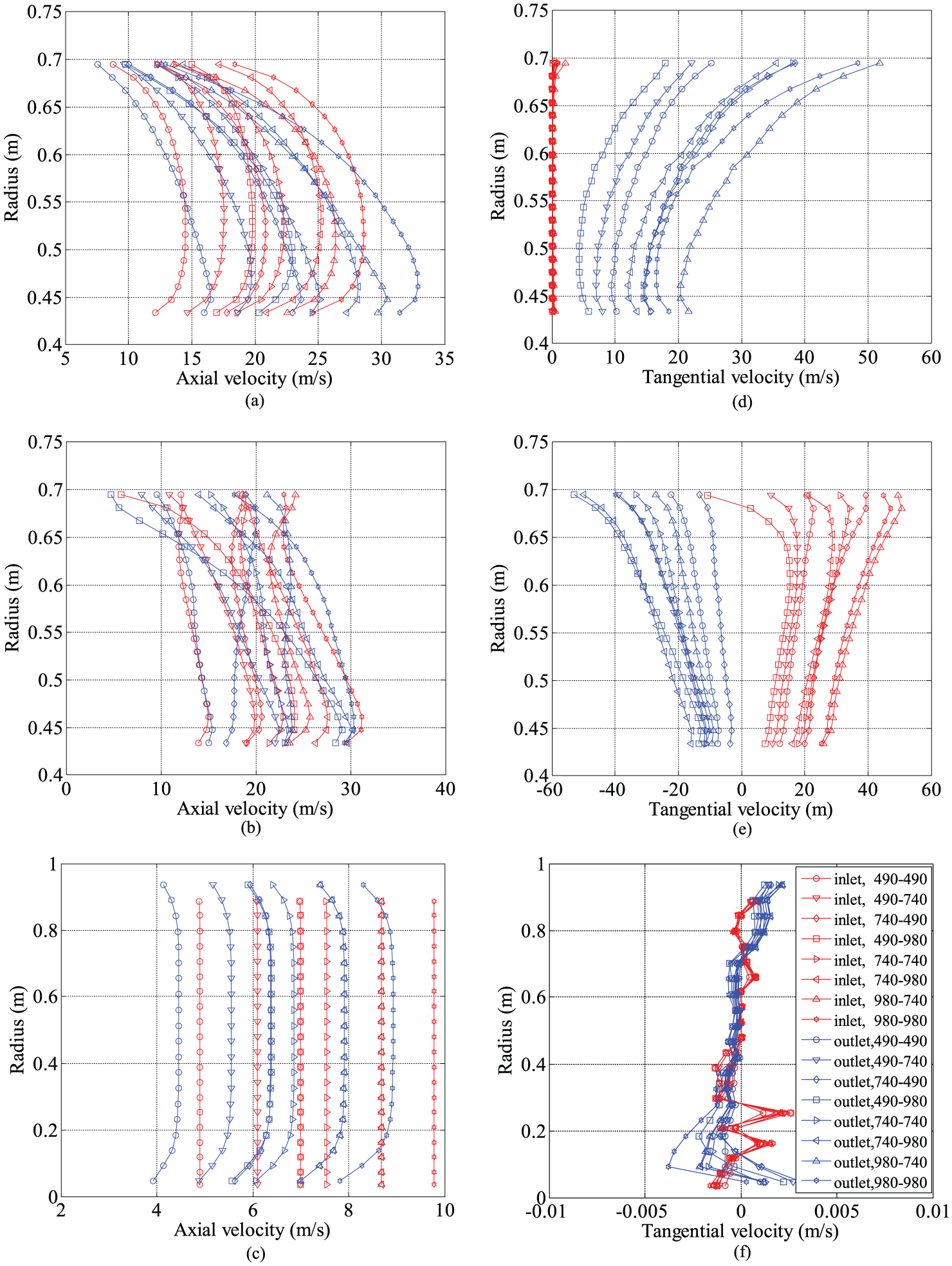
Distributions of the circumferentially averaged axial-flow velocities at the inlet and outlet of the (a) front impeller (along the blade height), (b) rear impeller (along the blade height), and (c) CRAFF; and the tangential velocities at the inlet and outlet of the (d) front impeller, (e) rear impeller, and (f) CRAFF during operation at the maximum efficiency with respect to the impeller speed combination.
Differential speed operation of CRAFF
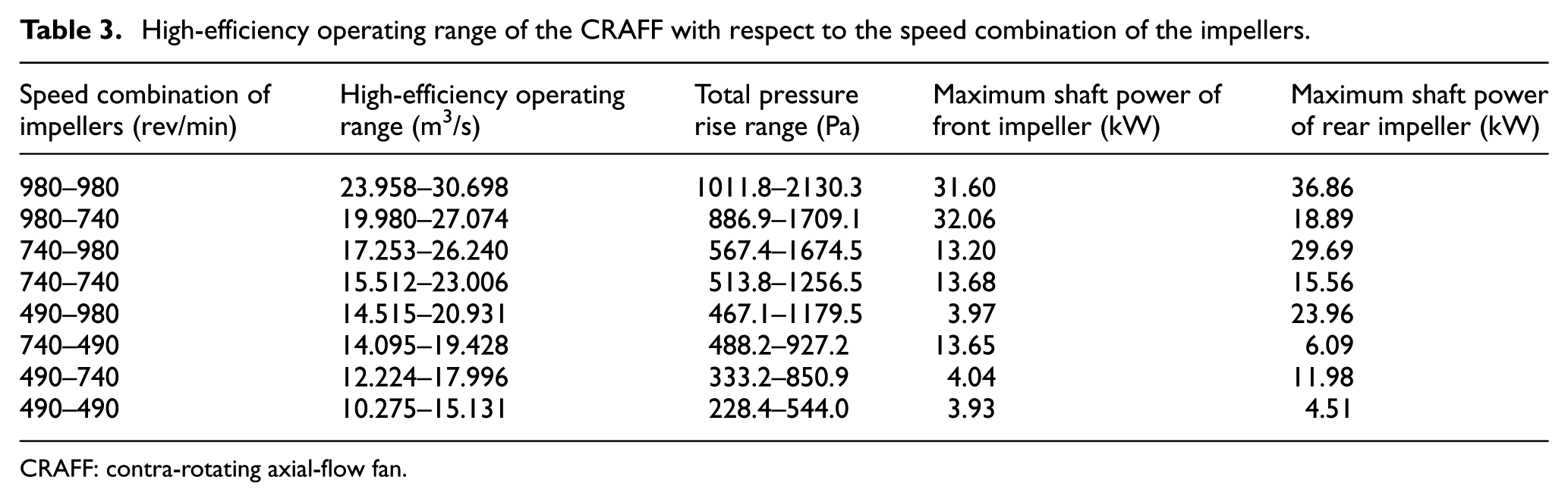
To ensure stable operation of the ventilation system, the total pressure rise in the CRAFF should be less than 0.9 times the highest total pressure rise, namely, Ht < 0.9Htmax. In addition, to save energy, the efficiency should not be less than 0.9 times the maximum efficiency for a given combination of the impeller speeds, namely, η ≥ 0.9ηmax. Table 3 gives the high-efficiency operating ranges of the CRAFF for different impeller speed combinations.
High-efficiency operating range of the CRAFF with respect to the speed combination of the impellers.
CRAFF: contra-rotating axial-flow fan.
The resistance characteristics of the ventilation pipe can be expressed as 21

where H is the pressure resistance of the ventilation pipe (Pa), H0 is the basic pressure resistance of the ventilation pipe (Pa), ζν is the resistance coefficient, and Q is the flow rate of the fan (m3/s). In the early stages of a mining operation, ζ ν is small, but increases in the later stages. Its specific value is experimentally determined.
Table 4 gives the predicted total pressure rise (Pa) of the CRAFF within the high-efficiency operating range with respect to the flow rate and impeller speed combination according to Table 3. Equation (6) was used to calculate the resistance of the ventilation network for a given flow rate. In addition, taking into consideration other leakage losses in the ventilation network, the total pressure rise in the CRAFF was determined. 17 Based on the desired flow rate and total pressure rise in the CRAFF, the speed combination of the two impellers can be selected using Table 4. The resistance of the ventilation pipe network would increase with increase in the length of the excavation tunnel, resulting in decreased flow rate if the rotational speeds of the impellers remain unchanged. However, if the flow rate in the CRAFF can be monitored, and the rotational speeds of the impellers can be automatically adjusted, it would be possible to maintain an approximately constant flow rate and high efficiency. The rotational speeds of the two impeller motors can be conveniently varied by the changing pole method.
Predicted total pressure rise (Pa) of the CRAFF within the high-efficiency operating range with respect to the flow rate and impeller speed combination.

CRAFF: contra-rotating axial-flow fan.
However, if the load ratio of a three-phase asynchronous motor is <50%, the motor efficiency would decrease rapidly. It is thus necessary to appropriately choose the rated powers of the two impellers when their rotational speeds are to be varied. Model YBF280S-6 motors with rated power and rotational speed of 45 kW and 980 rev/min, respectively, were used to drive the two impellers of the CRAFF in this study. A 6/8/12-pole, single-winding, three-speed asynchronous motor can be obtained from each of the employed motors by reverse pole changing and phase shifting. 22 The resultant rated power would be 45/33/10 kW. Computational fluid dynamics (CFD) analysis indicates that such a motor would not be overloaded when the fan is operated with differential impeller speeds, with their load ratios being >50% for most speed combinations.
Conclusion
A CRAFF used for mine ventilation was analyzed and its performance and internal total pressure rise and velocity distributions for different speed combinations of its two impellers were investigated by numerical simulation. The followings are the conclusions drawn from the findings:
The performance curve of the CRAFF varies with the flow rate, and the high-efficiency operating range also varies with the speed combination of the impellers. Variation in the rotational speed of the rear impeller has little effect on the total pressure rise and shaft power of the front impeller, but significantly affects the total pressure rise, shaft power, and stable operating range of the CRAFF. Furthermore, the rotational speed of the front impeller affects the flow rate and high-efficiency operating range of the CRAFF.
When the CRAFF is operated with the maximum efficiency and differing rotational speeds of the impellers, the total pressure rise distributions in the axial direction are similar to those for the design speed combination. Specifically, the total pressure rise at the front and rear impellers increase with increase in the rotational speeds of the impellers. The distributions of the total circumferentially averaged pressures in the radial direction are also similar to those for the design speed combination, with the distributions in the radial direction at the inlets of the two impellers and the CRAFF being nearly uniform. However, those at the outlets of the two impellers and the CRAFF are non-uniform. In addition, the total circumferentially averaged pressures at the outlets of the rear impeller and the CRAFF increase in the radial direction.
When the CRAFF is operated with the maximum efficiency for different impeller speed combinations, the axial velocity distributions at the inlet and outlet of the CRAFF along the blade height are uniform. Furthermore, the tangential velocity at the inlet and outlet of the CRAFF is almost zero.
The high-efficiency operating ranges of the CRAFF with regard to stability of operation and low energy consumption were determined with respect to the impeller speed combination. The findings can be used to select the speed combination of the two impellers based on the required flow rate and total pressure rise in the ventilation network. This can be done by adjusting the rated powers of the impeller motors through pole-changing control to ensure efficient operation.
Footnotes
Appendix 1
Handling Editor: Aditya Sharma
Declaration of conflicting interests
The author(s) declared no potential conflicts of interest with respect to the research, authorship, and/or publication of this article.
Funding
The author(s) disclosed receipt of the following financial support for the research, authorship, and/or publication of this article: This study was supported by the National Natural Science Foundation of China (No. 51275137).