
Abstract
A preliminary experimental investigation was performed with a focus on the axial pressure oscillations of self-resonating pulsed waterjet under different impinging surfaces. Five target plates of different impinging surfaces were impinged by self-resonating pulsed waterjets at various standoff distances and under four inlet pressures. It was found that the geometry of impinging surface significantly affects the pressure oscillation peak and amplitude of self-resonating pulsed waterjet, and the influences largely depend on the inlet pressure. Both the pressure oscillation peak and the amplitude increase to their maximum and then drop with increasing standoff distance, which is regardless of the geometry of impinging surface. But the geometry influences the values of the optimum standoff distance and the oscillation peak and amplitude. Compared with the trend of pressure oscillation peak against standoff distance, the oscillation amplitude can be more obviously changed by the impinging surface. Moreover, an assumption that the geometry affects the pressure oscillation peak by the rebound waterjets and hydroacoustic waves has been proposed based on related literature. Further study should be conducted to clarify the relations between the axial pressure oscillation and the geometry of impinging surface.
Keywords
Introduction
As a novel and non-conventional machining method, high-speed waterjet is experiencing a rapid development during the last few decades.1–3 A number of industrial and practical applications have made high-speed waterjet a significantly important technology being focused by many researchers. These applications include materials cutting, rock breaking, coating removal, and surface cleaning.4–6 High-speed waterjet includes but not limits to cavitating jet, self-resonating pulsed waterjet (SRPW), abrasive jet, pulsed jet, and rotating jet. SRPW is one that combines the advantages of both a cavitating jet and a pulsed jet, which makes it the subject of a relatively intense research effort in the literature.
The conception of SRPW was first proposed by Johnson et al., 7 aimed at augmenting the cavitation erosion capability of a submerged waterjet. This conception was based on the research performed by Crow and Champagne, 8 who experimentally found that the large-scale orderly patterns existing in the noise region could be enhanced and controlled by a slight periodic surging imposed at the jet exit. Another valuable work contributing to the occurrence of SRPW was carried out by Morel, 9 who concluded that jet instabilities couple with the Helmholtz resonance can generate very powerful pressure oscillations at a frequency slightly higher than the fundamental frequency of the resonator. SRPW is an unconventional waterjet that takes advantage of the natural tendency of an axisymmetric jet to organize into large structures, resulting in the formation of large ring vortices emitted for the nozzle. 10 These vortices then cavitate to form toroidal bubbles whose growth and collapse can cause very large pressure fluctuations, leading to water hammer effects. Thus, SRPW is much superior to a conventional waterjet with respect to the destructive power.
Considerable promise has been assigned to SRPW because of its strong cavitation and pulsation abilities. In more specific terms, by analyzing the erosion and cleaning effects of SRPW, Johnson et al. 11 claimed that the structured jet with large discrete vortex rings should promote cavitation to depths several times greater than for conventional jets in deep-hole drilling. Furthermore, Chahine et al. 12 gave an analytical and experimental study on the acoustics and flow field characteristics of SRPW, and they concluded that the intensification of bubble ring collapse can largely improve the cavitation erosion ability of the jet. With the efforts made by Li et al., 13 SRPW has been successfully applied in petroleum engineering in China. As a result, the average rate of penetration of tricone bits was enhanced by 31.2% and the bit footage was improved by 29.1%. Then, based on the characteristics of SRPW, Song et al. 14 developed a rapid solution-mining technology that can double the speed of construction at the pocket stage of cavern development.
In recent years, a growing interest is still observed in SRPW. For example, Fang et al. 15 experimentally and numerically studied the flow field inside an organ-pipe nozzle, which is capable of generating SRPW and is commonly used in research and applications. They found that the working pressure, and chamber length and diameter have a great influence on the cavitation intensity and velocity distribution of the jet. Moreover, Hu et al. 16 found a way of generating pulsed air–water jet by taking advantage of the mechanism of SRPW, which could be a way of promoting the application of the jet. In addition, Li et al.17,18 experimentally studied the effect of inner surface roughness of organ-pipe nozzle on the pressure and cavitation characteristics of SRPW. They concluded that there exists an optimal roughness value that can improve the cavitation intensity and the pressure oscillations of SRPW, depending on the inlet pressure and standoff distance. Also, Li et al. 19 demonstrated that area discontinuity at nozzle inlet greatly affects the pressure oscillations and the cavitation erosion intensity of SRPW, resulted from experimental investigations. They also conducted a preliminary investigation on the effect of feeding pipe diameter on the pressure oscillation characteristics of SRPW, 20 which provides a novel way to improve the impact power in applications.
Even though valuable insight into the working principles and generation mechanism of SRPW has been gained, to the best of our knowledge, rather limited work on the effect of disturbances or acoustic waves triggered by jet–target interactions has been reported. However, with respect to self-excited jet, Vinoth and Rathakrishnan 21 have pointed out that the geometry of impinging plate affects the feedback path of the upstream propagating acoustic wave. Similarly, Arthurs and Ziada 22 have reported that the acoustic tone generated by a high-speed jet impinging on a rigid plate is closely related to the jet instabilities and the resonant acoustic modes occurring between the nozzle and the plate. In one of the most basic research on self-excited jet, Rockwell and Naudascher 23 demonstrated that even many types of impingement geometry are capable of inducing self-sustained oscillations, the disturbance and acoustic sources are different, especially at high flow speeds. As a result, the inducement of localized vorticity fluctuations in the sensitive area of the free shear layer near separation will be affected. Moreover, it has been put forward in some literature that further analysis and attentions should be given to jet–target interaction to better distinguish the mechanism of self-excited jet.10,11 Most importantly, both of our previous experimental and numerical studies24,25 have already found that the geometry of impinging wall greatly influences the pressure characteristics of self-excited pulsed waterjets issuing from Helmholtz oscillators.
Therefore, it can be expected that the target plate geometry, which plays a dramatically important role in inducing disturbances and acoustic waves, should, to some extent, affect the characteristics of SRPW. And an investigation into these effects can help provide a better understanding of the generation mechanism of SRPW, which is able to make some contribution to producing more reasonable nozzle design principles. This can also guide the practical application of SRPW and result in a large improvement of the working efficiency of the jet.
The purpose of this study is an attempt to further understand the generation mechanism of SRPW by experimentally investigating the pressure oscillations of the jet affected by the jet–target interactions. In the experiment, five target plates of different impinging surfaces were used to produce different jet–target interactions, and the influenced pressure oscillation peak and amplitude of SRPW were measured and analyzed to evaluate the effects. This is actually a continuation of our earlier work on self-excited waterjet15–20,24–26 and serves as a supplement to the previous related researches.
Generation mechanism of SRPW
As is shown in Figure 1, an organ-pipe nozzle capable of generating SRPWs consists of an upstream contraction, a downstream contraction, and a resonant chamber. When a high-speed waterjet discharges from the nozzle, disturbances will be triggered at the downstream nozzle because of the sudden changes of pressure and velocity distributions. These disturbances then propagate upwards in the form of hydroacoustic waves and are reflected at the upstream contraction. The incident waves superimpose on the reflected ones, forming a standing wave under certain conditions. And peak resonance will occur if the fundamental frequency of the organ-pipe nozzle matches the preferred structuring frequency of the jet. 10 Then, with the interactions of the jet and environmental fluid, the hydroacoustically achieved excitation structures the shear layer into discrete, well-defined ring vortex of large scales. The volume fluctuations of the moving large-scale vortex rings arouse large pressure oscillations that can interrupt the jet, leading to the formation of SRPW.
Profile of an organ-pipe nozzle and schematic of the generation of SRPW.
In order to achieve the peak resonance in the chamber using the feedback mechanism, an empirical acoustic analysis is presented below, which should be useful for estimating the structural parameters of an organ-pipe nozzle.
First of all, the relation between the jet structuring frequency, fc, and Strouhal number, Sd, can be obtained from the research conducted by Crow and Champagne 8
where De is the nozzle exit diameter and Ue is the jet velocity.
For the hydroacoustic wave generated at the downstream contraction, it is expressed by
where λ is the wave length, c is the local sound speed, and f0 is the fundamental frequency.
Based on the formation conditions of standing wave, the pipe length for achieving resonance can be obtained as

where Lc is the chamber length, Dc is the chamber diameter, Ma is the Mach number and is defined as Ma = Ue/c, and n is the mode number.
The peak resonance happens when fc matches f0. Combining equations (1)–(3) results in 7

If we simplify equation (4) with a mode parameter, Kn, and add a correction factor, β, proposed by Chahine et al., 10 it can be rewritten as

where
Based on equation (5), the structural parameters of an effective organ-pipe nozzle will be determined if the exit diameter, model number, correction factor, and jet velocity are given.
More information on SRPWs can be found in Johnson et al., 7 Chahine and colleagues,10–12 and Li and colleagues.13,14,17–20,26 However, it should be noted that little existing literature has provided any analysis on the effects of the disturbances yielded by the jet–target interactions. Indeed, as sketched in Figure 1, these disturbances also propagate upward in the form of hydroacoustic waves, and force functions to the resonating chamber in the nozzle assembly, which should be expected to affect the mechanism described above to some extent.
Experimental setup and procedures
Since measuring the pressure fluctuation is one of the most important ways to quantify the performance of SRPW, 27 the experiment was designed to obtain the pressure oscillation peak and amplitude under different inlet pressures and standoff distances.
Facilities and setup
Figure 2 is the experimental setup for measuring the impact pressure of the submerged SRPW. The experiment was carried out on a multifunctional waterjet test bench developed by our research team independently and had been employed in our previous studies on self-resonating or self-excited waterjets.15,17–20,26

Schematic diagram of the experimental setup for jet pressure measurement.
The bench included a horizontal moving table having X motion and a loading platform having Y and Z motions. All the motions were regulated by the control table with an accuracy of 0.1 mm. The organ-pipe nozzle was mounted on the rod of the horizontal moving table through a fitting. A pressure transducer (type: BD Sensors DMK333) was installed on the fitting to monitor the inlet pressure under each test, aiming at eliminating the influence of different energy losses in the pipe line under different pump pressures. A tank filled with water was fixed on the loading platform with the target plate mounted on the inner side, and the target plate was communicated with the pressure transducer used to obtain the pressure oscillations, as shown in Figure 2. The axis of the organ-pipe nozzle could be made coaxial with that of the pressure tap by adjusting the locations of the platform in Y and Z directions. Standoff distance, S, was defined as the distance from the nozzle exit to the impinging surface of the target plate in X direction. During each test, S was changed from 20 to 100 mm with an interval of 10 mm.
Pressurized water was provided by a multi-stage plunger pump with a maximum pressure of 60 MPa, corresponding to a flow rate of 120 L/min. Four inlet pressures were applied in the experiment, which were 10, 15, 20, and 25 MPa. Moreover, two bladder accumulators were used to minimize the pressure and flow rate fluctuations of the pump. One was put near the pump and the other was located immediately close to the nozzle, as shown in the figure. More detailed information about the technical details of the experimental setup can be found in our previous research.17–20,26
Nozzles and target plates
Since the preferred chamber length is determined by the jet velocity (equation (5)), four organ-pipe nozzles corresponding to each inlet pressure were used in the experiment. Based on the related literature,10,11 the optimal Strouhal number, the correction factor, and the mode number were set as Sd = 0.3, β = 0.6, and n = 1, respectively. The inlet, chamber, and exit diameters were Di = 13 mm, Dc = 5 mm, and De = 2 mm, respectively, obtained from the “Organ-pine nozzle Design Manual” established by Li and Shen. 28 Then, using equation (5), the chamber lengths of the four organ-pipe nozzles could be achieved, which were 20, 17, 15, and 14 mm, corresponding to inlet pressures of 10, 15, 20, and 25 MPa, respectively. The exit length was Le = 5 mm for all the four nozzles, which was determined by the material strength. The photos of the nozzles are shown in Figure 3, where the nozzles with chamber lengths of 20, 17, 15, and 14 mm were numbered as I, II, III, and IV, respectively.

Photos of the organ-pipe nozzles.
Five target plates of different impinging surfaces were applied in the experiment. Specifically, the impinging surfaces were (a) concave spherical, (b) convex spherical, (c) pyramidal, (d) grooved, and (e) flat, respectively. The profiles and photos of the target plates are shown in Figures 4 and 5, respectively.

Profiles of the target plates of: (a) concave spherical, (b) convex spherical, (c) pyramidal, (d) grooved, and (e) flat surfaces.
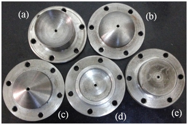
Photos of the target plates of: (a) concave spherical, (b) convex spherical, (c) pyramidal, (d) grooved, and (e) flat surfaces.
As is illustrated in the figures, each target plate had at its center a pressure tap with a diameter of 1 mm, which was smaller than that of the waterjet. Even though a diameter of 0.5 mm would be better, it was too difficult to be fabricated on different surfaces, especially the concave spherical and pyramidal ones. Moreover, our preliminary experiment had shown that the pressure oscillations of the jets under the pressure tap diameters of 0.5 and 1 mm had little difference.
Measurement and experimental uncertainties
Another pressure transducer (type: AE-H2) communicating with the pressure tap on the target plate was used to get the impact pressure during each test. Axial pressure oscillation peak, Pmax, and amplitude, Pa, were used to evaluate the oscillation characteristics affected by the geometry of impinging surface. And Pa was defined as

where Pmin is the minimum pressure. Both Pmax and Pmin could be directly read out from the laptop connected with the data logger (model: QuantumX MX840B). Preliminary tests based on the related researches7,10,20,28 have been performed to determine the sampling frequency, which was 19,200 Hz during each test.
Both the pressure transducers had been calibrated by the manufacturer before the experiment. And the experimental uncertainty mainly came from the accuracy of the pressure transducer obtaining the impact pressure. The main parameters of this pressure transducer are shown in Table 1.
Main parameters of the pressure transducer for measuring the impact pressure.

In addition, the accuracy of the pressure transducer monitoring the inlet pressure was ±0.5%FS. Even though this transducer also made some contribution to the experimental uncertainty, the influence was rather small and thus could be neglected.
More detailed information on the analysis of the experimental uncertainties can be found in Li et al. 26
Results and discussions
Axial pressure oscillation peak
Figure 6 shows the axial pressure oscillation peak of SRPW against standoff distance at four inlet pressures. In the legend, “Ca,”“Cv,”“Py,”“Gr,” and “Fl” stand for the concave spherical impinging surface, convex spherical impinging surface, pyramidal impinging surface, grooved impinging surface, and flat impinging surface, respectively.

Axial pressure oscillation peak against standoff distance at inlet pressures of: (a) 10MPa, (b) 15MPa, (c) 20MPa, and (d) 25MPa.
As is observed from the figure, all the curves are “S” shaped, with the left reversed to the right. That is to say, the pressure oscillation peak increases slightly with increasing standoff distance, and then starts to reduce sharply at a certain standoff distance, called the optimal standoff distance. So, at the optimal standoff distance, the pressure oscillation peak reaches a maximum, resulting in the largest impact of SRPW. The distributions of the pressure oscillation peak along standoff distance can provide valuable information for guiding the practical applications of SRPWs.
Moreover, the reversed S-shaped trend of Pmax versus S seems to be an inherent property that is unaffected by the geometry of the impinging surface, or the jet–target interactions. But the impinging surface can slightly affect the value of the optimal standoff distance, especially at relatively higher inlet pressures. For example, at inlet pressure of 10 MPa (Figure 6(a)), the optimal standoff distance for all the five cases is around 30 mm; while at inlet pressure of 25 MPa (Figure 6(d)), the optimal standoff distance for the flat impinging surface is 40 mm, which is 5 mm larger than the other four cases.
In terms of the trend of Pmax versus S, if compared with the results obtained by Li and Shen, 28 it can be found that the pressure oscillation peak drops much more violently here in the range of standoff distance from 40 to 70 mm. This is because the exit diameter of organ-pipe nozzle used in their experiment was 6 mm, which is three times the diameter used in this experiment. As a consequence, the momentum of the jet in their experiment is nine times greater at the same jet velocity, which can make the jet travel much farther without the axial dynamic pressure decaying significantly.
As is illustrated in Figure 6, the greatest difference caused by the different impinging surfaces occurs in the range of standoff distance from 30 to 70 mm at inlet pressures of 10 and 15 MPa, and in the range from 40 to 80 mm at inlet pressures of 20 and 25 MPa. This is most likely due to the fact that the large-scale structures, which are the foundation of generating SRPW, need a certain time to grow into vortex rings. The occurrence, growth, and collapse of these vortex rings can thus pulse the jet to generate pressure oscillations. And at higher pressures, the standoff distance where vortex rings start to take effect will be larger. From this point of view, it can also be claimed that the different geometries of impinging surface influence the pressure oscillation peak by affecting the large-scale structures or the vortex rings, which are triggered by the resonance in the chamber.
Even though the geometry of impinging surface has no effect on the trend of Pmax versus S, it obviously affects the value of the axial pressure oscillation peak, especially in the range of standoff distance where the greatest difference turns up. In more specific terms, at inlet pressures of 10 and 15 MPa (Figure 6(a) and (b)), the pyramidal impinging surface gives rise to the greatest pressure oscillation peak, while the concave spherical and grooved impinging surfaces lead to much smaller peaks. At inlet pressures of 20 and 25 MPa (Figure 6(c) and (d)), the flat impinging surface turns to be the one that brings about the greatest pressure oscillation peak. And it is of great interest to notice that the role of the grooved impinging surface suffers a dramatic experience with the increase in inlet pressure. At inlet pressures below 25 MPa, it results in almost the smallest pressure peaks at all the standoff distances, which is very similar to the role that the concave spherical surface plays. But at inlet pressure of 25 MPa, it makes the pressure oscillation peaks only smaller than the flat one does.
In order to provide an explanation on these observations, a schematic diagram illustrating the directions of the rebound jets and the hydroacoustic waves generated by the impingement of the incident jets is shown in Figure 7. And the green circles are indications of the rebound waterjets.

Schematic diagram of the rebound jets and hydroacoustic waves for target plates of: (a) concave spherical, (b)convex spherical, (c) pyramidal, (d) grooved, and (e) flat surfaces.
As is shown in Figure 7, the intensity of influence of the rebound waterjet is the greatest for the concave spherical surface and then the grooved surface, while the pyramidal surface creates the weakest intensity, followed by the convex spherical surface and then the flat one. As for the hydroacoustic waves reaching the chamber of the organ-pipe nozzle, the flat surface is able to cause the most intense ones, and then the grooved surface. The other three impinging surfaces can hardly reflect hydroacoustic waves to the chamber because the surfaces are not perpendicular to the axis of the jet. So, if we compare the intensities of the rebound waterjets and the effectively reflected hydroacoustic waves with the effects of the different surfaces, it can be found that the rebound waterjet and the hydroacoustic waves act on SRPWs differently, dramatically depending on the inlet pressure. More specifically, at relatively lower inlet pressure, the rebound waterjet affects the pressure oscillation peak much more violently than the hydroacoustic wave does; while at higher inlet pressures, their roles are reversed, meaning the hydroacoustic wave plays a more important role.
However, the feedback mechanism enhancing the organized oscillations is rather rich in complexity, especially when the disturbances caused by jet–target interactions are combined with the initial excitations generated at the downstream contraction. Much worse, there is currently little literature on the effects of jet–target interactions on SRPWs. Therefore, the forgoing discussion is kind of speculative, although some basis can be sought from the research work conducted by Rockwell and Naudascher. 23
Axial pressure oscillation amplitude
The axial pressure oscillation amplitude against standoff distance has been plotted in Figure 8. As is depicted in the figure, the pressure oscillation amplitude is much more stable against standoff distance under all the four inlet pressures, compared with the pressure oscillation peak versus standoff distance. Generally, the amplitude fist goes up slowly and then decreases gently with increasing standoff distance. Also, this trend of Pa versus S is still independent of the geometry of impinging surface. However, the geometry of impinging surface greatly affects the magnitude of the pressure oscillation amplitude, significantly depending on the inlet pressure. Furthermore, it should be noted that the same geometry affects the pressure oscillation peak and amplitude differently, even under the same inlet pressures. For example, although the pyramidal surface generates the largest pressure oscillation peaks at the inlet pressure of 10 MPa, it also leads to much smaller pressure oscillation peaks than the concave spherical surface does at the same pressure.

Axial pressure oscillation amplitude against standoff distance at inlet pressures of: (a) 10MPa, (b) 15MPa, (c) 20MPa, and (d) 25MPa.
As is shown in Figure 8(a) and (b), the concave spherical and grooved impinging surfaces result in the largest amplitudes at all the testing standoff distances, under inlet pressures of 10 and 15 MPa, while the pyramidal surface causes the largest amplitudes under inlet pressures of 20 and 25 MPa (Figure 8(c) and (d)). However, the flat surface causes the smallest amplitudes at inlet pressures of 10, 15, and 20 MPa. And it is of great interest to find that the concave spherical surface, which induces the largest amplitude at inlet pressure of 10 MPa, results in the smallest amplitudes at inlet pressure of 25 MPa. These phenomena indicate that the effects of the geometry of impinging surface are dramatically determined by the inlet pressure. Comparing Figures 7 and 8, it can be observed that a large pressure oscillation peak caused by a certain geometry of impinging surface does not necessarily mean a correspondingly large pressure oscillation peak.
Moreover, there also exists an optimal standoff distance where the pressure oscillation amplitude reaches a maximum. And the geometry of impinging surface affects this standoff distance greatly. For example, at inlet pressure of 10 MPa, this optimal standoff distances for the concave spherical, pyramidal, grooved, and flat surfaces are the same of 50 mm; while for the convex spherical surface, it is about 80 mm. So, the influence of the geometry of impinging surface on the pressure oscillation amplitude is more obvious than on the pressure oscillation peak.
It should be emphasized that the above discussions are limited to qualitative analyses, due to the lack of related literature on SRPWs, especially on the effects of the geometry of impinging surface. Therefore, the effects of pressure distribution on the impinging surface have been neglected. Further numerical and theoretical investigations should be performed to give a clarification on these phenomena.
Conclusion
Aiming at making a contribution to clarifying the generation mechanism of SRPW, the pressure oscillation peak and amplitude affected by the impinging surface were experimentally studied for the first time. Five target plates of different impinging surfaces were used under four inlet pressures and various standoff distances. An assumption for explaining the affected peak was also proposed. Even though the study was qualitative and preliminary, it also provides some results which could be useful information for some related researchers.
The trend of Pmax versus S is “S” shaped, with the left reversed to the right, which is regardless of the geometry of impinging surface.
At relatively lower inlet pressures, the rebound waterjet affects the pressure oscillation peak much more violently than the hydroacoustic wave does; while at higher inlet pressures, it is the other way around.
The effects of the geometry of impinging surface on the pressure oscillation amplitude are more obvious that on the peak. And the same geometry affects the peak and amplitude differently even under the same inlet pressure.
Theoretical or numerical investigations should be performed to further study the interactions between the geometry of impinging surface and SRPWs.
Footnotes
Academic Editor: Takahiro Tsukahara
Author note
Author Yong Kang is also affiliated with Collaborative Innovation Center of Geospatial Technology, 129 Luoyu Road, Wuhan, China.
Declaration of conflicting interests
The author(s) declared no potential conflicts of interest with respect to the research, authorship, and/or publication of this article.
Funding
The author(s) disclosed receipt of the following financial support for the research, authorship, and/or publication of this article: This research was financially supported by the National Key Basic Research Program of China (no. 2014CB239203), the National Natural Science Foundation of China (no. 51474158), and the China Scholarship Council (no. 201406270047).