
Abstract
Along with the continuous development of aviation detection and deep sea exploration technology, electronic equipment will face with increasingly complicated and harsh natural environment. Traditional circuit fault-repair methods based on redundant fault-tolerant technology are easy to implement. However, it has excessive hardware consumption and dissatisfied environmental adjustment. For this reason, a novel structure of embryonics electronic cell array based on functional decomposition and circular removal self-repair mechanism is designed, which can implement digital circuit with fault self-repair capacity, so as to gain higher reliability with lesser hardware resource consumption. The general structure and all submodules of the designed embryonics electronic cell array are designed and simulated. A new circular removal self-repair mechanism technology is put forward based on characteristics of the designed embryonics electronic cell array. Through successful simulation of a typical digital circuit implemented with the designed embryonics electronic cell array and self-repair strategy, feasibility of the proposed theory is verified. From the perspective of array’s reliability and hardware resource consumption, a comparison between the designed embryonics electronic cell array and the traditional embryonics electronic cell array is completed by simulation. The comparison results show that the proposed embryonics electronic cell array and self-repair mechanism not only ensure higher reliability of functional circuit but also effectively reduce hardware resource consumption of functional circuit.
Keywords
Introduction
With the rapid development of information technology, electronic system is becoming increasingly integrated, intelligent, and complicated, and working environment of electronic system is simultaneously more and more complicated and various, which puts forward higher requirements on reliability of electronic systems. Traditional circuit fault-repair methods based on redundant fault-tolerant technology are easy to implement, and it can improve the reliability of system to a certain extent. However, there are some limitations in the above methods, for example, excessively consumed hardware or dissatisfied environmental adjustment. 1 In order to solve the shortage of existing redundant fault-tolerant technology and meet the requirements of future electronic system, it is imperative to design a new kind of circuit structure.
Embryonics electronic cell array (EECA) is a hardware system with self-adaption, self-detection, and self-repair ability, inspired by the multicellular organisms’ cell division and differentiation mechanisms.2,3 Embryonic hardware was proposed by Mange and Marchal in 1996, it has immediately received wide attention of scholars both at home and abroad. At present, many results have been obtained both in theory and practical application. Researches on EECA structure around the world mainly include the following: the basic structure of EECA was introduced and the basic design of EECA was given. 4 A honeycomb architecture of EECA was proposed, which enriches connection between embryonics cells;5,6 a three-dimensional embryonics cell structure was studied and embryonics hardware was developed into three-dimensional space.7,8 EECA was divided into a control module array and a function module array, with different statuses for two neighbor cells. 9 An adaptive reconfigurable multicellular EECA architecture named eTissue was proposed, which was based on marked and identified data processing method.10,11 Prokaryotic EECA structure and self-healing strategy were researched, which reduces hardware resource consumption of EECA.12–14 The EECA structure based on bus was studied, it enriches connection between embryonics cells and improves efficiency of self-repair method.15,16 A novel EECA structure with local connection and remote connection was studied, which enriches connection between embryonics cells. 17
In existing EECA, embryonics cell is the basic functional unit, which has a small functional particle size. For a complex functional circuit, the achievement of circuit with existing EECA is relatively complex and with huge hardware resource consumption. Therefore, a novel EECA structure based on functional decomposition is proposed, of which the basic functional unit is functional module. Fault detection is the premise of self-repair. However, there are some limitations in the existing fault detection methods, for example, limited detection module, low fault coverage, or excessively consumed hardware. According to the characteristics of digital circuits, a new fault detection method is designed. Based on the characteristics of the designed EECA structure, a circular removal self-repair mechanism (CRSRM) technology is proposed for fault self-repair. In order to analyze the performance of the designed EECA in this paper, a comparison between the classical two-dimensional EECA structures and the designed EECA is completed. Reliability and hardware resource consumption of two kinds of EECA are researched.
The rest of the article is organized as follows. In section “Structure of embryonic electronic cell array,” the basic theory and structure of the designed EECA is introduced. In section “Structure of functional module,” the functional module is designed and implemented. In section “Structure of fault detection module,” the theory and structure of a new fault detection method is studied. In section “Bus structure and communication protocol,” connections between functional module and fault detection are researched. In section “CRSRM for designed EECA,” CRSRM for the designed EECA is studied. Section “Experiment and analysis” describes the simulation analysis and experiment of the designed EECA and self-repair strategy. Section “Comparison with a classical EECA” states a comparison between the classical two-dimensional EECA and the designed EECA. In section “Conclusion,” the article is concluded. Simulation results and comparison results show the feasibility and effectiveness of the proposed EECA structure and self-repair strategy.
Structure of embryonic electronic cell array
Human body is a large and complex self-repair system, which can be seen as a complex multifunctional system composed of brain, limbs, and other organs. Different organs complete their respective functions, and all organs work together under the control of brain. If there is a lesion in organ, brain will get the lesion signal and control the organ to complete self-repair function, so as to ensure the normal working of human body.
Based on the working process and basic principle of human body, the idea of functional decomposition is applied to the design of EECA. As we all know, the main function of EECA is to complete the corresponding circuit functions, and in case of circuit malfunction, initiating self-repair function of EECA, so as to guarantee the circuit work normally for a long time. Therefore, the designed EECA is composed of functional modules to achieve some circuit functions, detection modules to detect faults of functional module, and bus to achieve modules’ communication. The function of detection module is to monitor working status of functional module and control self-repair function of EECA. Bus completes the transportation and communication of data and signal, with the designed EECA structure as shown in Figure 1.

Structure of designed EECA.
For a large or very large scale complex functional circuit, first, the complex functional circuit is decomposed into several small simple circuits. Then, these simple circuits are mapped to functional modules and different functional modules complete their corresponding function. Finally, all functional modules work together to complete the function of functional circuit. Fault detection modules monitor the working status of functional module in real time. When there is a fault in functional module, fault signal will be generated to start self-repair function of faulted functional module, and other functional modules are not affected. Based on the basic principle of human endocrine system, bus is used as communication channel of different modules and facilitates the signal transmission of different modules. The working process of the designed EECA reduces complexity of complex functional circuit implementation and locates the fault to a smaller range. Since self-repair only happens within a located scale, it avoids heavy hardware resource consumption caused by global fault detection and fault self-repair.
Structure of functional module
Functional module, the basic unit of EECA, mainly completes basic functions of circuit. Structure of the designed functional module is shown in Figure 2.

Structure of functional module.
As is shown in Figure 2, functional module is composed of work cells, idle cells, and auxiliary cell. Work cells mainly perform the corresponding circuit functions. Idle cells are prepared for self-repair of faulted work cells. Auxiliary cell mainly completes the information interaction between functional modules and bus, and monitors the working status of all cells within functional module and controls cell’s working status according to the working status of functional module. A chain-based connection between work cells and idle cells forms a cell ring and auxiliary cell directly connects to all other cells. According to the scale and design requirement of circuit, the number of work cells and idle cells in functional module can be flexibly chosen.
Structure of embryonic electronic cell
Embryonics cell is the most basic unit of EECA, with each cell implementing the respective function, and all embryonics cells work together to complete global circuit function. Work cells have the same structure with idle cells in functional module, and the embryonics cell structure is shown in Figure 3, which is composed of gene configuration memory, functional unit, input/output (I/O) module, and control module.
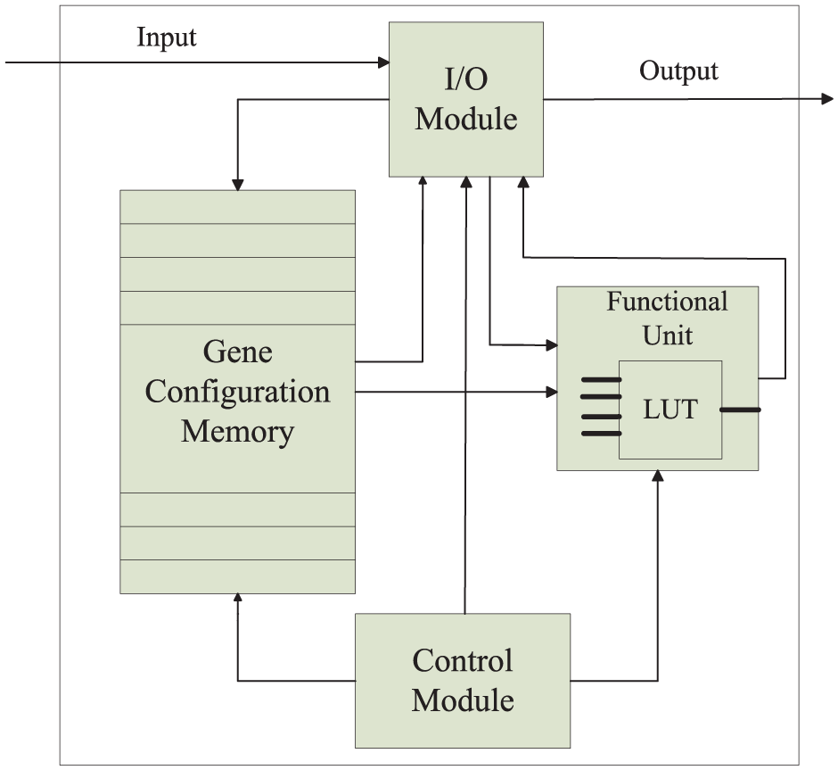
Structure of work cell.
Gene configuration memory
Gene configuration memory is similar to nucleus, mainly storing configuration information needed during the process of working, self-repair, and wiring of cell, and the configuration information is similar to the DNA in nucleus. The work cells in functional module are in chain-based connection, so each cell only needs to store its own configuration information needed during working and self-repair process. The nature of gene configuration memory is an SRAM. Configuration information is mainly composed of cell configuration information and backup configuration information. Cell configuration information is information needed for working process, and backup configuration information is information needed for self-repair process. In consideration of structural characteristics of embryonics cell and connection characteristics in functional module, backup configuration information is almost the same as the cell configuration information.
During self-repair process, the nature of cell movement is the movement and reconfiguration of configuration information. According to the characteristics of functional module, the connection of gene configuration memories is shown in Figure 4.
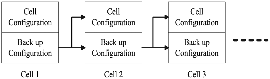
Connection of gene configuration memories.
As shown in Figure 4, backup configuration of gene configuration memory in Cell 1 links to cell configuration and backup configuration of gene configuration memory in Cell 2, backup configuration of gene configuration memory in Cell 2 links to cell configuration and backup configuration in Cell 3, and the other gene configuration memories in functional module have the same connection. In case of a fault in work cell, its backup configuration information passes to the next cell’s cell configuration and backup configuration at the same time, so as to realize self-repair of the functional circuit and ensure the completeness of genes.
Gene configuration information mainly includes look-up table (LUT) functional configuration information, cells’ working statuses, delay configuration, and the respective backup configuration information. The functions and lengths of various parts in gene configuration are shown in Table 1. The length of the utilized gene is 68 bits, with bits from 0 to 15 for cell function configuration information, bits from 16 to 31 for cell input selection signal, the bit of 32 for cell status, the bit of 33 for delay configuration, and bits from 34 to 67 for backup gene configuration.
Assignment of gene in embryonics cell.

Functional unit
Functional unit, an important part of embryonics cell, mainly executes the specific functions of embryonics cell and achieves different functions through the expression of different kinds of gene configuration information. Functional unit is mainly composed of four input LUTs. LUT chooses the corresponding output signal according to different input signals, and it can achieve any logic function with input not more than four through the expression of the corresponding gene configuration. The structure of the designed functional unit is shown in Figure 5.

Structure of functional unit.
In Figure 5, I0, I1, I2, and I3 are inputs of LUT; Out is output of functional unit; O0 is input of trigger; O1 is output of D flip-flop; FC is configuration information of LUT; C0 is delay control signal; c1, c2, c3, and c4 are control signals of LUT input selection; and clk is clock signal.
Input signal is mainly divided into input outside of functional module and input from the other cells within functional module; input signal of LUT is chosen by a 16-1 multiplexer under the control of selection signal. FC is configuration information of LUT, deciding the specific logic functions of LUT. The trigger is to ensure the realization of sequential circuits.
I/O module in embryonics cell completes signal transportation between cells, determines the relationship between input signal and output signal according to cell’s working status. If the cell works normally, the input signal enters the cell and the output signal is obtained through functional unit. If there is a fault in cell, cell becomes transparent status and input signal is directly regarded as its output signal.
Control module in embryonic cell completes the control of all modules during the working process of cell, such as controlling the configuration of cell configuration information, the transfer of gene configuration information, and the transition of cell statuses. Based on the status control signal of auxiliary cell, the working statuses of cells can be obtained and all cells have two statuses: working status and transparent status. Control module makes feedback of cell’s working status to auxiliary cells and gets the working status of cells at the next time according to the working status of functional module.
Structure of auxiliary cell
In order to realize the information exchanged between the functional modules and the bus, and control the working statuses of all cells based on the working statuses of functional modules, auxiliary cell in functional module is designed. An auxiliary cell is mainly composed of gene configuration module, control module, and I/O module, with structure design as shown in Figure 6.

Structure of auxiliary cell.
The main function of control module in auxiliary cell is to determine the working status of all cells in functional module, and produce status control signal of all cells based on the working status of functional module and current working statuses of all cells. If functional module fails, self-repair of functional module starts or the existing working status remains unchanged.
I/O module in auxiliary cell is mainly used for information transfer between functional module and bus. It achieves bus signal inputs into functional module and functional module output signal passes to bus. Functional module output signal is composed of data signal and address signal, and bus input signal concludes data signal without address information.
Gene configuration module stores all configuration genes needed during the working process of auxiliary cell. Configuration gene includes output selection control signal of functional module during the working process, input selection control signal of functional module, mark bits of e-output signal and mark bits of input signal. Distribution of genes in gene configuration module is shown in Table 2.
Assignment of gene in auxiliary cell.
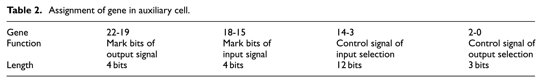
The length of configuration gene is 23 bits, with the bits from 0 to 2 for output selection control signal of functional module, bits from 3 to 14 for input selection control signal of functional module, bits from 15 to 18 for mark bits of output signal, and bits from 19 to 22 for mark bits of input signal.
Structure of fault detection module
Fault detection is the premise of self-repair in EECA; real time and coverage of fault detection method directly affect the performance of EECA. Existing fault detection methods are mainly cell-in fault detection, and fault detection primarily focuses on functional unit and gene configuration memory. But for circuit wiring, I/O module, and control module, there are no effective fault detection methods. Existing fault detection methods for functional unit are redundant fault tolerant,18–20 and fault detection for gene configuration memory is expended hamming coding.15,21 For a large or very large scale functional circuit, the hardware resource consumption of existing fault detection methods is huge, and fault coverage is limited. Therefore, a new fault detection method based on the function of functional module is proposed.
In traditional embryonics cell, fault detection of functional unit is based on double modular redundancy; the theory of double modular redundancy fault detection is shown in Figure 7. Input signal passes through actual functional module and redundant functional module at the same time, comparing the results of two modules, if the results are the same, there is no fault in actual functional module, which means Fault = 0, else, there is fault in actual functional module, which means Fault = 1.

Double modular redundancy fault detection.
In this paper, fault detection is not only for every embryonics cell but also for every functional module. Based on the theory of double modular redundancy and memory, the designed fault detection module is shown in Figure 8. The fault detection module mainly consists of SRAM and XOR gate, memory module stores the corresponding output signals of different functional modules under different input signals, and XOR gate completes XOR between theoretical output signal and actual output signal. The result of XOR gate is regarded as working status monitoring signal of functional module, so as to complete real-time fault detection of functional modules.
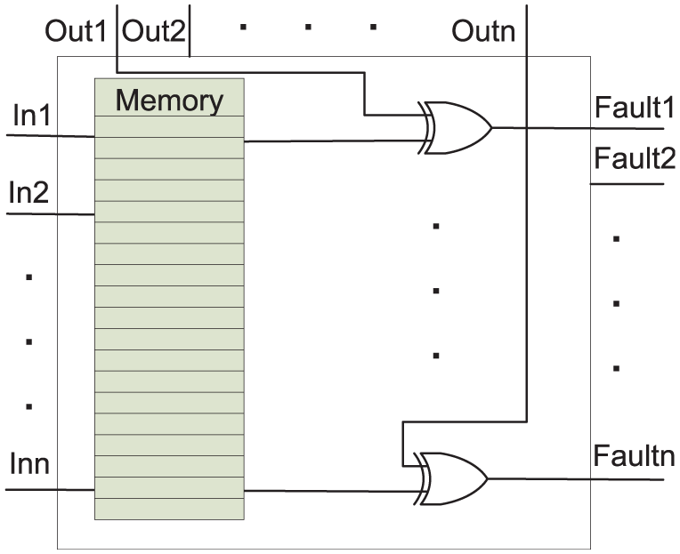
Structure of fault detection module.
In Figure 8, I1-In represents input signals of detection module, which are input signal of each functional module. Out1-Outn represents actual output signals of all functional modules. Fault1-Faultn represents working status signals of all functional modules. Faultx = 1 means there is a fault in functional module x, and Faultx = 0 means the functional module x works normally (1 ≤ x ≤ n).
Each fault detection module can monitor several functional modules at the same time, and the width of bus will increase with the increasing of functional modules. Considering the width of bus, a fault detection module completes the fault detection of nine functional modules. When functional circuit is mapped to EECA, the storage information in fault detection module is correspondingly confirmed.
Bus structure and communication protocol
In reference to literature,15,16 bus is chosen as data transmission channel of the designed EECA. However, each data line in digital circuit can only transmit one signal at the same time, so the way of bus time-sharing multiplexing is adopted to simulate endocrine communication. In order to make data communicate successfully between the functional modules in the absence of bus controller, data structure, and communication protocol of bus are studied.
Bus data structure
The designed bus is composed of data bus and control bus, in which data bus is used for data transmission in working process. And control bus is responsible for transmission of all kinds of control signals in working process; it consists of fault signal line, commanding signal line, and address signal line. Bus data structure is shown in Table 3.
Bus data structure.

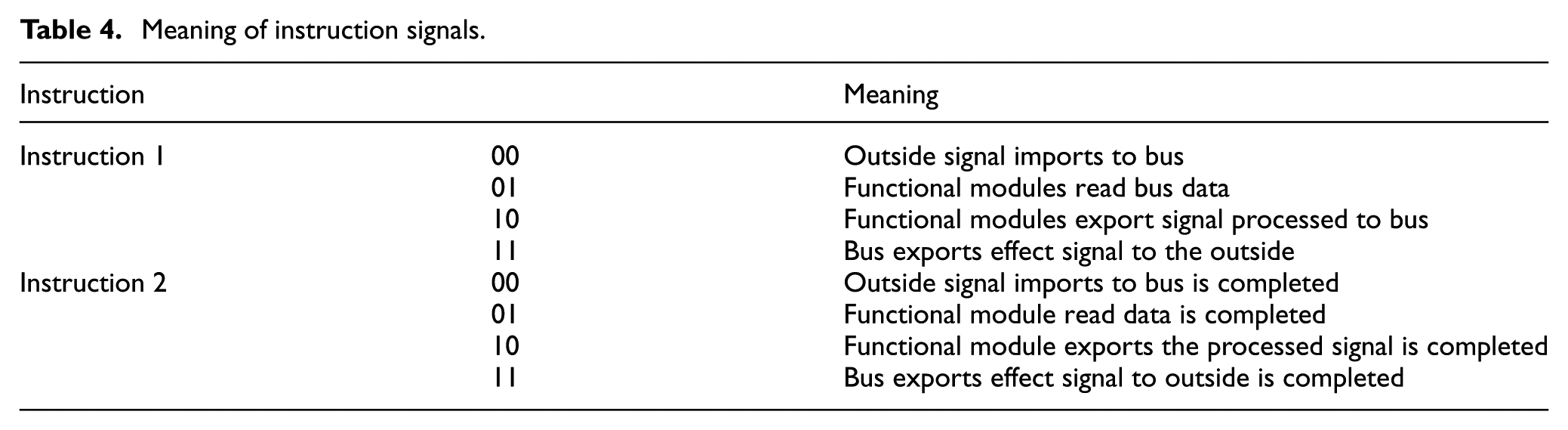
The widths of all parts in bus are not fixed, which can be set according to different objects. The main functions of each part in bus are shown as follows: data bus is responsible for data transmission. Fault signal line is responsible for passing the working statuses of all functional modules, and functional modules implement different controls with different working status signals. Address signal line is responsible for transmission of address information and identification of functional modules. Instruction signal line is divided into two parts: one part responsible for the data operation of functional module, namely, inputting data or outputting data, and the other part is responsible for the feedback of bus data processing results from functional modules. The meaning of instruction signals is shown in Table 4.
Meaning of instruction signals.
Based on bus communication mode, one-to-one or one-to-many communication between any functional modules can be realized in the designed EECA. Inputs and outputs of functional modules and fault detection module are connected to corresponding data lines and control lines in bus, with the connection is shown in Figure 9.

Connection between bus and functional modules and detection module.
Bus communication protocol
Bus structures in electronic technology usually have bus controllers to make sure all units connected to bus work orderly. The designed EECA requires all functional modules and fault detection modules work independently, and all modules can realize independent communication. Bus controller may cause the risk of controller failure and reduce reliability of the system, so Instruction 1 and Instruction 2 are used to replace the functions of bus controller with different codes. All modules implement different operations by testing the codes of Instruction 1 and Instruction 2 to complete the transmission of data. Bus communication protocol is the guarantee of realizing normal data communication, with the designed communication protocol is shown as follows:
1. Bus input.
When Instruction 1 is 00 and fault signal is 0, external signal is imported to bus; when Instruction 2 is 00, input process is completed.
2. Bus output.
When Instruction 1 is 11 and fault signal is 0, bus exports signal to external part; when Instruction 2 is 11, output process is completed. When the fault signal is 1, bus does not export signal to external part.
3. Modules read data from bus.
When Instruction 1 is 01 and fault signal is 0, functional modules and fault detection modules read the data from bus, and modules determine whether to process the data by judging the address information from address signal line. When Instruction 2 is 01, modules read data process finished.
4. Modules export data to bus.
When Instruction 1 is 10 and fault signal is 0, functional modules and fault detection modules export data to bus, and modules are ready to pass output data to next targeted functional module. When Instruction 2 is 10, data output process is finished. When fault signal is 1, the output signal of functional module is only transmitted to fault detection module, only when the fault signal is 0, and the output signal of functional module is transmitted normally.
CRSRM for designed EECA
According to characteristics of the designed EECA, CRSRM for fault self-repair is proposed, with the flowchart of self-repair strategy is shown in Figure 10.
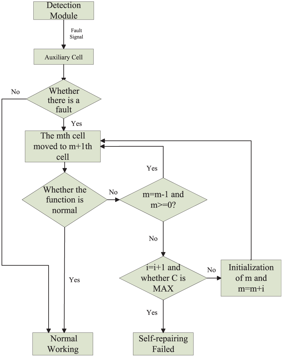
Flowchart of self-repair strategy.
In Figure 10, m represents the last work cell in functional module during the working process, i represents the number of circulation, and C represents the maximum number of cycles during the circular removal self-repair process. Self-repair process of functional module is described as follows: fault detection modules detect the working statuses of functional modules in real time, transmit working status signals to auxiliary cell in functional modules, and determine the working statuses of functional modules according to working status signals. If there is a fault signal in a functional module, self-repair function will start immediately. Gene configuration information of cell m in the functional module moves backward to cell m + 1, and cell m becomes transparent. Fault detection module detects whether the function of EECA is normal at the moment: if the function of EECA is normal, self-repair process of functional module is succeeded; if the function of functional module is still abnormal, the transparent cell changes into idle cell. The relationship between m − 1 and 0 is judged: if m − 1 ≥ 0, functional module repeats the above self-repair steps; if m − 1 < 0, one round of self-repair is over. i = i + 1 is executed and whether C is maximum is judged: if C does not reach the maximum, EECA can continue to repeat the self-repair process; if C reaches the maximum, EECA cannot complete the self-repair and functional module cannot work normally. Take a single-cell fault for example, its self-repair principle is shown in Figure 11.

Process of single-cell fault self-repair.
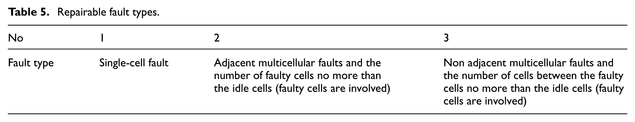
If there is a single-cell fault in functional module, it can be definitely repaired within a self-repair cycle. For multicellular faults happened at the same time, when the number of faulty cells is greater than the number of idle cells, EECA can’t achieve successful fault self-repair. When the number of faulty cells is less than the number of idle cells, EECA can complete self-repair according to the designed self-repair strategy. If all faulty cells are adjacent or the number of cells between faulty cells does not exceed the number of idle cells (faulty cells are involved). When the number of cells between faulty cells is more than the number of idle cells (faulty cells are involved), EECA is unable to complete self-repair. Repairable fault types of functional module are shown in Table 5.
Repairable fault types.
Experiment and analysis
In order to verify the proposed EECA and CRSRM, a typical digital circuit is chosen to do simulation experiment and analysis, with the logical expression of typical digital circuit is shown as follows

The truth table of the chosen digital circuit is shown in Table 6.
Truth table of verification circuit.

Function of the chosen circuit is relatively simple, which can be realized by one functional module. The chosen functional circuit can be decomposed into five small functional circuits. One small functional circuit is implemented by one work cell; the first five cells are used to implement circuit function. Three idle cells are chosen in functional module, which are used to the self-repair of functional circuit. Five small functional circuits can be represented as formula (2)

The new truth table is shown in Table 7.
Truth table of decomposed circuit.

The connection between the cells and the functions of cells is mapped to all cells, with the obtained genes of cells as shown in Table 8, in which x means the bit can be 0 or 1, and it is not fixed.
Genes of working cells.
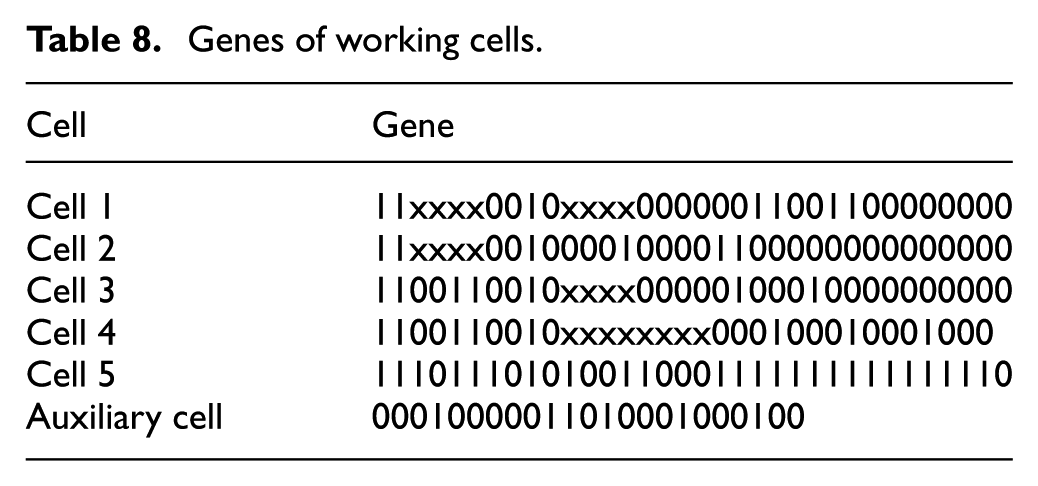
According to the design of the proposed EECA, x is chosen as 1 for the convenience of simulation. And Xilinx ISE Design Suite 12.2 is used to simulate the chosen functional circuit, with the simulation result of the functional circuit is shown in Figure 12.

Functional simulation of the chosen circuit.
In Figure 12, clk is clock signal, which is clock-rising-edge-trigged. reset is reset signal, in which reset = 1 means the reset of functional module. Fault is working status signal of functional module, in which fault = 1 means there is fault in functional module, and fault = 0 means functional module works normally. Cell1out-cell5out represents output signals from cell 1 to cell 5 in functional module (cell6out-cell8out are not used). C1WGIN–C8WGIN is configuration genes for cell 1 to cell 8. If the configuration gene of cell is 0, it is a free cell. Busin[7:0] is input signal of functional module, busin[4]–busin[7] are mark bits of input signals, and busin[0]–busin[3] are four input signals A, B, C, and D, which are c1in–c4in (c5in–c8in are not used). busout[4:0] is output signal of functional module, busout[1]–busout[4] are mark bits of output signals, and busout[0] is the value of output signal. As shown in Figure 12, the time within 0–125 ns is initialization phase, clock signal rising edge triggered. When input signal busin[0]–busin[3] = 1100, c1in = 1, c2in = 1, c3in = 0, c4in = 0. Due to signal transmission delay between cells, after 40 ns, output of cell 4 cell4out = 1; after 40 ns, output of cell 5 cell5out = 1; after 10 ns, output signal busout[0] = 1. Similarly, when input signals busin[0]–busin[3] are 0000–0010, considering signal delay time, output signal busout[0] is 0 from 215–515 ns. When input signals busin[0]–busin[3] are 0010–0110, output signal busout[0] is 0. When input signals busin[0]–busin[3] are 0111–1111, output signal busout[0] is 1. The results is shown in Figure 12 are the same with the truth table shown in Table 7.
In order to verify the proposed CRSRM, single-cell fault self-repair is simulated. If there is a fault in functional module, the self-repair process of EECA is shown in Figure 13.

Self-repair simulation of single-cell fault.
In Figure 13, when busin[0]–busin[3] is 0111, as is shown in Table 7, busout[0] should be 1. Before 165 ns is initial stage of circuit, considering signal transmission delay, in 225 ns, busout[0] is 1, circuit works normally, and fault = 0. In 325 ns, cell4out changes from 1 to 0,which leads cell5out to change from 1 to 0, and in 385 ns, busout[0] changes from 1 to 0, which means there is fault in circuit. Considering signal transmission delay, in 495 ns, fault changes from 0 to 1, which starts the self-repair of circuit. In 605 ns, the gene of cell 5 transfers to cell 6, and cell 5 becomes a transparent cell, which works as a line busout[0] is 0. fault = 1, which means fault is not repaired, and self-repair process should continue. In 845 ns, gene of cell 4 transfers to cell 5, and cell 4 becomes a transparent cell, which works as a line. In 905 ns, cell5out changes from 0 to 1; in 945 ns, cell6out changes from 0 to 1; in 965 ns, busout[0] changes from 0 to 1, which means circuit works normally; and in 1055 ns, fault changes from 1 to 0. Through two times gene movement and expression, fault self-repair process is completed. Therefore, the output signal of functional module is normal, and the fault is fixed. There is no fault in EECA, and the circuit implemented by EECA works normally again.
Comparison with a classical EECA
In order to verify advantages of the designed EECA, from the perspective of reliability and hardware resource consumption in EECA, a comparison between the designed EECA and classic EECA is completed. Hardware resource consumption mainly includes the implementation of EECA, fault detection of EECA, and self-repair of EECA. The selected classic EECA is two-dimensional EECA (2DEECA).
Reliability analysis of EECA
In literature,22–24k-out-of-m model is used to research the reliability of 2DEECA with row (column) removal self-repair mechanism (RRSRM) and single-cell removal self-repair mechanism (SCRSRM). For a 2DEECA with the scale of M × N, the scale of work array is m × n, where M and m represent the numbers of rows in EECA and working EECA. N and n represent the numbers of columns in EECA and working EECA (M ≥ m and N ≥ n). Therefore, reliability of EECA with RRSRM is shown as follows

The reliability of SCRSRM is shown as follows

In formula (4),
For the proposed EECA and self-repair strategy, if all functional modules s work normally, the system will work normally. For each functional module, if k cells work normally in all w cells, the functional module can work normally, which meets k-out-of-m model. Reliability of a functional module working normally is shown as follows

And reliability of the proposed EECA is shown as follows

In order to guarantee the scale of EECA is the same, the number of work cells is assumed as 10,000 and the number of idle cells is assumed as 6000. The scale of work cells array is m × n = 100 × 100, and the scale of the EECA is M × N = 128 × 125. In all functional modules, supposing the number of work cells is five and the number of idle cells is three. The failure rate for each cell is λ = 1 × 10⁻⁶ per hour. Reliability of three kinds of self-repair strategies is shown in Figure 14.

Reliability curve under three situations.
In Figure 14, reliability of 2DEECA with SCRSRM is the maximum and reliability of 2DEECA with RRSRM is the minimum. Before 0.8 × 10⁵ h, reliability of the proposed EECA with CRSRM is the same as the 2DEECA with SCRSRM; after 0.8 × 10⁵ h, reliability of the designed EECA with CRSRM begins to decline gradually, so the reliability is less than 2DEECA with SCRSRM, and it is much larger than 2DEECA with RRSRM.
Hardware resource consumption analysis
Hardware resource consumption is an important index to measure the structure and working process of EECA. Through the analysis of hardware resource consumption in EECA implementation, fault detection, and self-repair process, a comparison on hardware resource consumption is carried out, which is between the designed EECA with CRSRM and 2DEECA with RRSRM and SCRSRM.
Hardware resource consumption analysis of EECA implementation
According to the analysis, hardware resource consumption of EECA implementation is mainly composed of hardware resource consumption of embryonics cells and wiring, in which wiring resource consumption is mainly divided into wiring in cells and extracellular connection wiring. For a functional circuit, different design methods may cause differences in wiring consumption, and it is difficult to study the wiring resource consumption for there is no unified standard. Embryonics cells are the basic unit of EECA, and hardware resource consumption of embryonics cells is mainly discussed. In embryonics cell, chip area needed to store gene configuration information is the main hardware resource consumption. In classic EECA, 95% of the hardware consumption comes from gene storage.19,25 The structure of the designed embryonics cell is similar to that of the classic embryonics cell, and the body resource consumption of embryonics cell also comes from gene storage. For 2DEECA with RRSRM, each embryonics cell needs to store gene information of all cells with the same column; for 2DEECA with SCRSRM, each embryonics cell needs to store gene information of all work cells in EECA. For the designed EECA with CRSRM, each embryonics cell only stores gene information of itself and backup gene information for self-repair. For working cell array with the scale of m × n, the scale of whole EECA is M × N (M ≥ m and N ≥ n). The number of gene storage information in the above three EECA is shown in Table 9, in the assumption that gene configuration information of each cell is α.
Comparison of gene storage.
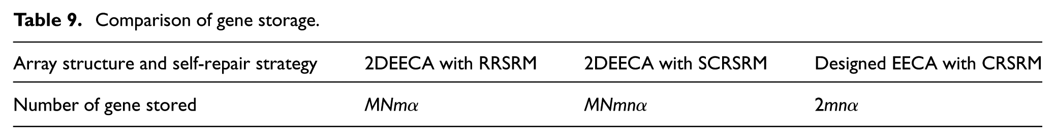
The number of gene information stored in 2DEECA is related to the scale of working array and whole EECA, but the number of gene information stored in the designed EECA is only related to the scale of working array. As shown in Table 9, the number of gene information stored in 2DEECA with SCRSRM is n times larger than that of 2DEECA with RRSRM, with the times only related to columns of working array. The number of gene information stored in 2DEECA with SCRSRM is MN/2 times larger than that of the designed EECA with CRSRM. The number of gene information stored in 2DEECA with RRSRM is MN/2n times larger than that of the designed EECA with CRSRM. So, hardware resource consumption ratio between 2DEECA with SCRSRM and 2DEECA with RRSRM is n, with the times related to columns of working array. Hardware resource consumption ratio between 2DEECA with row SCRSRM and the designed EECA with CRSRM is MN/2, with the times only related to the scale of entire EECA. Hardware resource consumption ratio between 2DEECA with RRSRM and the designed EECA in CRSRM is MN/2n, with the times related to the scale of working array and columns of EECA.
Hardware resource consumption analysis of fault detection
Fault detection module is an important module of embryonics cells, which is the premise of self-repair in EECA. Fault detection method of classic 2DEECA is cell-in fault detection, primarily focusing on functional unit and gene configuration memory module. However, there are few researches on control module, circuit wiring, and I/O module. The existing fault detection method for functional modules is redundant fault-tolerant, and fault detection for gene configuration memory is expended hamming coding based on coding. As a result, hardware resource consumption of functional module’s fault detection is mainly researched.
In 2DEECA, fault detection module exists in every embryonics cell, existing function unit is mainly implemented by LUT, and the fault detection of functional modules means the redundancy of LUT. Assuming the hardware resource consumption of fault detection for functional module in every embryonics cell is β, the scale of work cell array is m × n and the scale of EECA is M × N (M ≥ m and N ≥ n), so hardware resource consumption of fault detection for 2DEECA is MNβ. The proposed fault detection method is based on the function of functional module, which only detects the function of every functional module. The design of the proposed fault detection method is based on functional redundancy, also implemented by LUT. So, hardware resource consumption of fault detection in designed EECA is mnβ/5, and hardware resource consumption ratio of fault detection between the 2DEECA and the designed EECA is 5 MN/mn, with the times related to the scale of working array and entire EECA.
Hardware resource consumption analysis of self-repair
EECA can guarantee high reliability of functional circuit with self-repair function, and the essence of self-repair is idle cells replace faulty cells in EECA, with faulty cells acting as the a conductor. Different self-repair mechanisms mean different hardware resource consumption during self-repair process. There are two main self-repair mechanisms in the classic 2DEECA: RRSRM and SCRSRM. Considering the characteristics of designed EECA, a new CRSRM is proposed.
For work array with the scale of m × n, the scale of entire EECA is M × N (M ≥ m and N ≥ n). During row removal self-repair of 2DEECA, when there is a fault in a row of EECA, all cells in that row will be removed. N embryonics cells will be consumed for repairing one fault, and 2N embryonics cells will be consumed for repairing two faults. With the increasing of repair times, the number of consumed embryonics cells increases in sequence. During single-cell removal self-repair process of 2DEECA, when there is a fault in EECA, only the faulted cell will be removed. One embryonics cell will be consumed for repairing one fault, and two embryonics cells will be consumed for repairing two faults. With the increasing of repair times, the number of consumed embryonics cells increases in sequence. In circular removal self-repair process of the designed EECA, when there is a fault in EECA, only the faulted cell will be removed, and one embryonics cell will be consumed for repairing one fault. From the analysis of section “Hardware resource consumption analysis of EECA implementation”), the approximate resource consumption of three self-repair mechanisms in completing γ (0 ≤ γ ≤ maximum self-repair times) times of self-repair is shown in Table 10 (α is the number of gene storage information in a single cell). Hardware resource consumption of wiring is not considered during self-repair of EECA, for wiring in EECA is too complicated.
Hardware consumption of self-repair.

According to the analysis of Table 10, supposing that the number of working cells is10,000, the number of idle cells is 6000, the scale of working cells array is m × n = 100 × 100, and the scale of the EECA is M × N = 128 × 125. The maximum theoretical times of row removal self-repair are 28, and the maximum theoretical times of single-cell removal self-repair are 6000. Supposing that there are five working cells and three free cells in each functional module, the maximum theoretical times of circular removal self-repair are three in every functional module. Considering the fault occurring in different functional modules, relationship between the number of hardware resource consumption and self-repair times is shown in Figure 15.

Hardware resource consumption with self-repair times.
As shown in Figure 15, with the increasing of self-repair times, hardware resource consumption of three kinds of self-repair strategies increases linearly, hardware resource consumption of 2DEECA with RRSRM is the largest, hardware resource consumption of 2DEECA with SCRSRM is less than that of the former, and hardware resource consumption of the designed EECA with CRSRM is far less than that of the two formers. With the same self-repair times, hardware resource consumption ratio between 2DEECA with SCRSRM and the designed EECA with CRSRM is MN/2, with the times only related to the scale of the entire EECA. Hardware resource consumption ratio between 2DEECA with RRSRM and the designed EECA with CRSRM is MN 2 /2n, with the times related to the scale of entire EECA and columns of work array.
In section “Comparison with a classical EECA,” a comparison is carried out between the designed EECA with CRSRM and 2DEECA with SCRSRM and RRSRM. The differences in reliability of EECA, resource consumption on implementation of EECA, resource consumption on fault detection, and resource consumption on self-repair process are studied. For the designed EECA with CRSRM, compared with the classic 2DEECA with SCRSRM, with the increasing of working time, reliability will decrease a little, but it is still in a high status, and it is far more than that of 2DEECA with RRSRM. At the same time, hardware resource consumption of the designed EECA with CRSRM has been reduced to a certain extent on implementation of EECA, fault detection, and self-repair process. With the difference in scale of EECA, the decrement is not the same. When the scale of working array is confirmed, hardware resource consumption reduces significantly as the scale of EECA is larger.
Conclusion
EECA is a new type of bionic hardware system with self-diagnosis, self-adaption, and self-repair ability, inspired by multicellular organisms’ cell division and differentiation mechanisms. EECA can effectively improve reliability of electronic system, reduce huge hardware resource consumption brought by traditional redundant fault-tolerant design, and improve adaptability of electronic system to all kinds of adverse circumstances. Therefore, it has high research and application values.
Based on the idea of functional decomposition and fault detection method based on functions of functional module, a novel EECA structure is designed. And simulation of the designed EECA and all modules in EECA are completed. Through functional simulation experiment of a typical circuit, the rationality of designed EECA structure is verified. Based on characteristics of the designed EECA, a new CRSRM is proposed. And the applicability of the proposed self-repair strategy is analyzed. Based on fault self-repair simulation of a typical circuit, the effectiveness of the proposed CRSRM is demonstrated.
From the perspective of array’s reliability and hardware resource consumption, a comparison between the classical EECA and the designed EECA is completed by simulating. The results show that EECA and self-repair strategy proposed in this article not only ensure higher reliability of functional circuit but also effectively reduce hardware resource consumption of functional circuit. The reduction of hardware resource consumption is related to the scale of EECA. Overall speaking, the larger scale of the EECA, the larger reduction of hardware resource consumption.
In the future, functional circuit experiment based on field programmable gate array will be researched. In order to reasonably design functional circuit with the designed EECA in this paper, work cells and idle cells number choose method in functional module must be studied.
Footnotes
Academic Editor: ZW Zhong
Declaration of conflicting interests
The author(s) declared no potential conflicts of interest with respect to the research, authorship, and/or publication of this article.
Funding
The author(s) disclosed receipt of the following financial support for the research, authorship, and/or publication of this article: This study was supported by the National Nature Science Foundation of China (nos 61271153 and 61372039).